EP1419891B1 - Vacuum platen assembly for fluid-ejection device - Google Patents
Vacuum platen assembly for fluid-ejection device Download PDFInfo
- Publication number
- EP1419891B1 EP1419891B1 EP03013756A EP03013756A EP1419891B1 EP 1419891 B1 EP1419891 B1 EP 1419891B1 EP 03013756 A EP03013756 A EP 03013756A EP 03013756 A EP03013756 A EP 03013756A EP 1419891 B1 EP1419891 B1 EP 1419891B1
- Authority
- EP
- European Patent Office
- Prior art keywords
- vacuum
- sidewalls
- media
- fluid
- platen
- Prior art date
- Legal status (The legal status is an assumption and is not a legal conclusion. Google has not performed a legal analysis and makes no representation as to the accuracy of the status listed.)
- Expired - Lifetime
Links
- 239000000443 aerosol Substances 0.000 claims description 31
- 230000000694 effects Effects 0.000 claims description 7
- 239000012530 fluid Substances 0.000 description 20
- 239000002245 particle Substances 0.000 description 15
- 239000000428 dust Substances 0.000 description 11
- 238000000034 method Methods 0.000 description 7
- 238000010586 diagram Methods 0.000 description 6
- 238000007639 printing Methods 0.000 description 5
- 238000004519 manufacturing process Methods 0.000 description 3
- 239000007787 solid Substances 0.000 description 2
- 230000006978 adaptation Effects 0.000 description 1
- 230000000712 assembly Effects 0.000 description 1
- 238000000429 assembly Methods 0.000 description 1
- 230000006735 deficit Effects 0.000 description 1
- 230000002401 inhibitory effect Effects 0.000 description 1
- 238000001746 injection moulding Methods 0.000 description 1
- 238000007641 inkjet printing Methods 0.000 description 1
- 239000000463 material Substances 0.000 description 1
- -1 media debris Substances 0.000 description 1
- 230000002265 prevention Effects 0.000 description 1
- 238000005096 rolling process Methods 0.000 description 1
Images


Classifications
-
- B—PERFORMING OPERATIONS; TRANSPORTING
- B41—PRINTING; LINING MACHINES; TYPEWRITERS; STAMPS
- B41J—TYPEWRITERS; SELECTIVE PRINTING MECHANISMS, i.e. MECHANISMS PRINTING OTHERWISE THAN FROM A FORME; CORRECTION OF TYPOGRAPHICAL ERRORS
- B41J11/00—Devices or arrangements of selective printing mechanisms, e.g. ink-jet printers or thermal printers, for supporting or handling copy material in sheet or web form
- B41J11/0085—Using suction for maintaining printing material flat
-
- B—PERFORMING OPERATIONS; TRANSPORTING
- B41—PRINTING; LINING MACHINES; TYPEWRITERS; STAMPS
- B41J—TYPEWRITERS; SELECTIVE PRINTING MECHANISMS, i.e. MECHANISMS PRINTING OTHERWISE THAN FROM A FORME; CORRECTION OF TYPOGRAPHICAL ERRORS
- B41J11/00—Devices or arrangements of selective printing mechanisms, e.g. ink-jet printers or thermal printers, for supporting or handling copy material in sheet or web form
- B41J11/02—Platens
- B41J11/08—Bar or like line-size platens
Definitions
- Inkjet printers have become popular for printing on media, especially when precise printing of color images is needed. For instance, such printers have become popular for printing color image files generated using digital cameras, for printing color copies of business presentations, and so on.
- An inkjet printer is more generically a fluid-ejection device that ejects fluid, such as ink, onto media, such as paper.
- some fluid-ejection devices utilize a vacuum effect to keep the media properly in place.
- a vacuum effect to keep the media properly in place.
- a number of vacuum holes fluidly coupled with a vacuum source such as a centrifugal blower, can provide this vacuum effect.
- the vacuum-induced flow may also pull in media debris dislodged from the media, dust particles in the air, as well as aerosol, which includes fluid particles generated when the fluid is ejected.
- the media debris and aerosol can collect on the sidewalls of the vacuum holes, reducing the flow area they provide, and thus reducing vacuum capacity and the ability to maintain positioning of the media.
- US2002/0015670 A1 discloses a vacuum platen and a method for use of the platen in a printing device.
- the platen has a plurality of vacuum holes having sidewalls that are parallel to one another and extend at right angles to the main surface of the platen.
- US 6 270 215 discloses a vacuum platen according to the preamble of claim 1.
- EP 1 304 225 A2 discloses a fixed material transportation apparatus having a transporting device which is provided with a plurality of suction holes, which can be tapered towards the upper surface thereof.
- FIG. 1 is a diagram of a representative vacuum platen assembly of a fluid-ejection device, according to an embodiment of the invention.
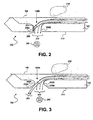
- FIG. 2 is a diagram of a side profile of the vacuum platen assembly of FIG. 1 in more detail that shows the undesirable aerosol, dust particle, and media debris collection substantially prevented by embodiments of the invention.
- FIG. 3 is a diagram of a side profile of the vacuum platen assembly of FIG. 1 in more detail that shows how the profiles of the sidewalls of a vacuum hole substantially prevent aerosol, dust particle, and media debris collection, according to an embodiment of the invention.
- FIGs. 4 and 5 are diagrams of other profiles of the sidewalls of a vacuum hole of a vacuum platen assembly that substantially prevent aerosol, dust particle, and media debris collection, according to varying embodiments of the invention.
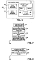
- FIG. 6 is a block diagram of a fluid-ejection device, according to an embodiment of the invention.
- FIG. 7 is a flowchart of a method, according to an embodiment of the invention.
- FIG. 8 is a flowchart of a method for manufacturing a vacuum platen assembly, according to an embodiment of the invention.
- FIG. 1 shows a representative vacuum platen assembly 100 for a fluid-ejection device, according to an embodiment of the invention.
- the fluid-ejection device may be, for instance, a black-and-white and/or color inkjet printer for outputting ink onto media, such as paper. More generally, the fluid-ejection device outputs fluid onto media.
- the vacuum platen assembly 100 includes a vacuum platen 101. As shown in FIG. 1 , the vacuum platen 101 is positioned against a drive roller 110, over which a pinch roller 108 is positioned. Media 106 is fed through the drive roller 110 and the pinch roller 108 by forced rotation of the drive roller 110. As the media 106 then moves over the vacuum platen 101, a fluid-ejecting mechanism 112, such as a fluid-ejecting head like an inkjet printhead, moves back and forth over the media 106, ejecting fluid onto the media 106, which may be paper.
- a fluid-ejecting mechanism 112 such as a fluid-ejecting head like an inkjet printhead
- the vacuum platen assembly 100 includes a number of ribs 104A, 104B, ..., 104M, collectively referred to as the ribs 104, that extend from the vacuum platen 101.
- the vacuum platen assembly 100 also includes a number of vacuum holes 102A, 102B, ..., 102N, collective referred to as the vacuum holes 102. There may be more or less of the vacuum holes 102 as compared to the ribs 104.
- the vacuum holes 102 extend completely through the vacuum platen 101, and provide a fluid connection with an external vacuum source, such as a centrifugal blower.
- the media 106 As the media 106 is fed between the pinch roller 108 and the drive roller 110, it passes over the vacuum platen 101. To maintain positioning of the media 106 against the ribs 104, the vacuum or suction effect provided by the external vacuum source, transmitted via vacuum holes 102, suctions the media 106 against the ribs 104. The fluid-ejecting mechanism 112 then moves back and forth over the media 106 to eject fluid onto the media 106.
- one of the ribs 104 is situated between every successively rolling pair of the holes 102.
- the rib 104A is situated between the holes 102A and 102B.
- Ejection of the fluid by the fluid-ejecting mechanism 112 can result in fluid aerosol, which includes very small airborne particles of fluid. Furthermore, movement of the media 106 can result in media debris becoming dislodged from the media 106.
- the aerosol and the media debris may be carried by vacuum airflow towards the vacuum holes 102. Although some of the aerosol and the media debris may be suctioned through the holes 102, other of the aerosol and the media debris may collect on the sidewalls of the holes 102, creating a blockage of air flow and inhibiting vacuum performance, or suction ability. Other types of debris that may collect on the sidewalls of the holes 102 include dust particles.
- FIG. 2 shows a scenario 200 that depicts the collection of aerosol, dust particles, and media debris on the sidewalls of vacuum holes, which is at least substantially prevented by embodiments of the invention.
- a side profile of a portion of the vacuum platen 101 is shown in detail, including the vacuum hole 102B.
- the vacuum hole 102B has sidewalls 208A and 208B, collectively referred to as the sidewalls 208, that are parallel to one another and at right angles to the lower surface 212 of the vacuum platen 101.
- the media 106 moves from left to right across FIG. 2 .
- Dust particles, fluid aerosol, and media debris are depicted in FIG. 2 by solid dots, such as the dots included within the dotted area 210.
- the fluid aerosol and media debris may become suctioned towards the vacuum hole 102B.
- the paths that air flow, aerosol, and debris so follow in their movement towards the hole 102B are represented by the arrows 202 and 204.
- the arrows 202 represent the motion of vacuum-induced air flow generated by an external vacuum source, represented by the blower symbol 240, such as a centrifugal blower.
- the arrows 204 represent the motion of those aerosol and debris particles which cannot fully make the turn into and thus cannot be suctioned through the vacuum hole 102B. Rather, such aerosol and debris collides with and collects on the sidewall 208A of the hole 102B, resulting in the collection of fluid aerosol and media debris 206. The collection of aerosol and debris 206 may build up on the sidewalls 208 over time, resulting in a clogging effect and reducing vacuum flow through the hole 102B.
- FIG. 3 shows a scenario 300 that depicts the at least substantial prevention of the collection of dust particles, aerosol, and media debris on the sidewalls of vacuum holes, according to an embodiment of the invention.
- a side profile of a portion of the vacuum platen 101 is shown in detail, including the vacuum hole 102B.
- the vacuum hole 102B again has sidewalls 208A and 208B, collectively referred to as the sidewalls 208.
- the sidewalls 208 are non-straight and non-parallel sidewalls that taper away from one another, and that are not at right angles to the lower surface 212 of the vacuum platen 101. They are non-straight because each sidewall has at least one point where internal surfaces thereof meet.
- the sidewall 208A has its internal surfaces meet at the point 302A
- the sidewall 208B has its internal surfaces meet at the point 302B.
- the sidewalls 208 are non-parallel because none of their internal surfaces are parallel to one another.
- the sidewalls 208 can be formed by backside-countersinking the vacuum hole 102B. That is, the sidewalls 208 can be formed by countersinking the vacuum hole 102B at the lower surface 212 of the platen 101.
- the media 106 moves from left to right across FIG. 3 .
- Dust particles, fluid aerosol, and media debris are again depicted in FIG. 3 by solid dots, such as the dots included within the dotted area 210.
- the dust particles, fluid aerosol, and media debris may become suctioned towards the vacuum hole 102B, in the direction of the arrows 202 or 204.
- the arrows 202 represent the motion of vacuum-induced air flow generated by an external vacuum source, represented by the blower symbol 240, such as a centrifugal blower.
- the arrows 204 that represent the motion of aerosol and debris, which in the scenario 200 would have collected on the sidewalls 208 of hole 102B, are now suctioned through the vacuum hole 102B, and do not collide with and collect on the sidewall 208A of the hole 102B.
- the profiles of the sidewalls 208 of the hole 102B are such that they are not in the path of aerosol and debris particle travel, and at least substantially prevent such collection of aerosol and debris on the sidewalls 208. That is, in the embodiment of FIG.
- the tapering, non-parallel, and/or non-straight nature of the sidewalls 208 allow even the relatively fast moving aerosol and debris to travel through the hole 102B.
- the profiles of the sidewalls 208 thus at least substantially prevent reduction, or impairment, of the vacuum-induced airflow through the vacuum hole 102B that may otherwise result if the aerosol and debris were to collect on either of the sidewalls 208.
- the profiles of the sidewalls 208 of the vacuum hole 102B are configured so that the collection of media debris and aerosol on the sidewalls 208 is at least substantially prevented.
- Sidewall profiles other than that depicted in FIG. 3 can be used to achieve this same effect.
- Two such alternative profiles are depicted in FIGs. 4 and 5 .
- Those of ordinary skill within the art can appreciate that embodiments of the invention are not limited to the sidewall profiles depicted in FIGs. 3 , 4, or 5 , however.
- FIG. 4 shows an embodiment of the invention in which the sidewalls 208 of the vacuum hole 102B are tapered, such that the opening of the hole 102B at the upper surface 402 of the vacuum platen 101 is smaller than the opening of the hole 102B at the lower surface 212 of the platen 101.
- the sidewalls 208 in the embodiment of FIG. 4 are thus non-parallel, like the sidewalls 208 in the embodiment of FIG. 3 , but not non-straight, unlike the sidewalls 208 in the embodiment of FIG. 3 .
- the sidewalls 208 in the embodiment of FIG. 4 are not non-straight because they do not have internal surfaces that meet at one or more points, unlike the sidewalls 208 in the embodiment of FIG. 3 .
- FIG. 5 shows an embodiment of the invention in which the sidewalls 208 of the vacuum hole 102B are formed by a backside counter-bore 502, from the lower surface 212 of the vacuum platen 101, such that the opening of the hole 102B at the upper surface 402 of the platen 101 is smaller than the opening at the lower surface 212.
- the sidewalls 208 in the embodiment of FIG. 5 thus result from backside counter-boring of the hole 102B, like the sidewalls 208 in the embodiment of FIG. 3 do, but are not non-parallel, unlike the sidewalls 208 in the embodiments of FIGs. 3 and 4 .
- the sidewalls 208 in the embodiment of FIG. 5 are non-straight and non-parallel, however.
- the sidewalls 208 in the embodiment of FIG. 5 are non-straight because they have internal surfaces that meet at one or more points. For instance, the internal surfaces of the sidewall 208A meet at the points 504A, whereas the internal surfaces of the sidewall 208B meet at the points 504B.
- the vacuum hole 102B has been shown in and described in conjunction with FIGs. 3 , 4, and 5 as a representative hole of the vacuum holes 102 of the vacuum platen assembly 100 of FIG. 1 .
- other and/or additional of the vacuum holes 102 of the platen assembly 100 may have sidewall profiles as depicted in FIGs. 3 , 4, and 5 .
- all of the vacuum holes 102 of the assembly 100 may have the same sidewall profile as that depicted in FIG. 3 , 4, or 5 .
- FIG. 6 shows a block diagram of a representative fluid-ejection device 600, according to an embodiment of the invention.
- the fluid-ejection device 600 may be an inkjet printer, or another type of fluid ejection device.
- the fluid-ejection device 600 includes a fluid-ejection mechanism 602, a media-feeding mechanism 604, and the vacuum platen assembly 100, a particular embodiment of which is depicted in FIG. 1 .
- the fluid-ejection mechanism 602 ejects fluid onto media, such as ink onto media like paper.
- the mechanism 602 may be an inkjet-printing mechanism.
- the mechanism 602 may include a fluid-ejecting head, such as a fluid-ejecting head like an inkjet printhead.
- the media-feeding mechanism 604 feeds media for ejection of fluid thereon by the fluid-ejecting mechanism 602.
- the mechanism 604 includes the rollers 108 and/or 110 of FIG. 1 .
- the vacuum platen assembly 100 is specifically depicted in FIG. 6 as including ribs 104, vacuum holes 102, and the platen 101.
- the vacuum holes 102 have sidewalls that have profiles to substantially prevent collection of dust particles, media debris, and aerosol thereon.
- the vacuum holes 102 may be that as has been shown in and described in conjunction with FIG. 3 , 4, or 5 .
- the ribs 104 extend from the platen 101, and the vacuum holes 102 transmit vacuum from the external vacuum source to maintain positioning of media against the ribs 104.
- FIG. 7 shows a method 700, according to an embodiment of the invention.
- the method 700 can be utilized in conjunction with the vacuum platen assembly 100 of FIG. 1 , the vacuum hole sidewall profiles of FIG. 3 , 4, or 5 , and/or the fluid-ejection device 600 of FIG. 6 .
- media is moved past ribs that extend from a vacuum platen (702), which can result in media debris being dislodged from the media.
- the media is suctioned against the ribs (704), due to the suction effect of the external vacuum source transmitted by the vacuum holes within the platen. Fluid is then ejected towards the media (706), which can result in aerosol.
- the aerosol and the debris are at least substantially suctioned through the vacuum holes of the platen (708), because the sidewalls of the holes have profiles as have been shown in and described in conjunction with FIG. 3 , 4, or 5 .
- the sidewalls may be non-parallel to one another.
- FIG. 8 shows a method 800 for manufacturing a vacuum platen assembly, according to an embodiment of the invention.
- the method 800 can be utilized to manufacture the vacuum platen assembly 100 of FIG. 1 , the vacuum holes of which have sidewall profiles of FIG. 3 , 4, or 5 .
- a platen is provided that has ribs extending therefrom (802).
- Vacuum holes are then formed within the platen (804).
- the vacuum holes at least substantially prevent the collection of debris on their sidewalls, due to the sidewalls having profiles as have been shown in and described in conjunction with FIG. 3 , 4, or 5 .
- the sidewalls may be non-parallel to one another.
- the platen with the ribs and the vacuum holes may be provided at the same time, such as via a single injection-molding operation.
Landscapes
- Handling Of Sheets (AREA)
- Ink Jet (AREA)
Description
- Inkjet printers have become popular for printing on media, especially when precise printing of color images is needed. For instance, such printers have become popular for printing color image files generated using digital cameras, for printing color copies of business presentations, and so on. An inkjet printer is more generically a fluid-ejection device that ejects fluid, such as ink, onto media, such as paper.
- To maintain positioning of the media while fluid is being ejected onto the media, some fluid-ejection devices utilize a vacuum effect to keep the media properly in place. For example, a number of vacuum holes, fluidly coupled with a vacuum source such as a centrifugal blower, can provide this vacuum effect. However, the vacuum-induced flow may also pull in media debris dislodged from the media, dust particles in the air, as well as aerosol, which includes fluid particles generated when the fluid is ejected. The media debris and aerosol can collect on the sidewalls of the vacuum holes, reducing the flow area they provide, and thus reducing vacuum capacity and the ability to maintain positioning of the media.
-
US2002/0015670 A1 discloses a vacuum platen and a method for use of the platen in a printing device. The platen has a plurality of vacuum holes having sidewalls that are parallel to one another and extend at right angles to the main surface of the platen. -
US 6 270 215 discloses a vacuum platen according to the preamble of claim 1. -
EP 1 304 225 A2 discloses a fixed material transportation apparatus having a transporting device which is provided with a plurality of suction holes, which can be tapered towards the upper surface thereof. - It is an object of the invention to provide a vacuum platen assembly having a reduced tendency of collecting media debris and aerosol on the sidewalls of its vacuum holes.
- This object is achieved by a vacuum platen assembly in accordance with claim 1.
- The drawings referenced herein form a part of the specification.
-
FIG. 1 is a diagram of a representative vacuum platen assembly of a fluid-ejection device, according to an embodiment of the invention. -
FIG. 2 is a diagram of a side profile of the vacuum platen assembly ofFIG. 1 in more detail that shows the undesirable aerosol, dust particle, and media debris collection substantially prevented by embodiments of the invention. -
FIG. 3 is a diagram of a side profile of the vacuum platen assembly ofFIG. 1 in more detail that shows how the profiles of the sidewalls of a vacuum hole substantially prevent aerosol, dust particle, and media debris collection, according to an embodiment of the invention. -
FIGs. 4 and 5 are diagrams of other profiles of the sidewalls of a vacuum hole of a vacuum platen assembly that substantially prevent aerosol, dust particle, and media debris collection, according to varying embodiments of the invention. -
FIG. 6 is a block diagram of a fluid-ejection device, according to an embodiment of the invention. -
FIG. 7 is a flowchart of a method, according to an embodiment of the invention. -
FIG. 8 is a flowchart of a method for manufacturing a vacuum platen assembly, according to an embodiment of the invention. - In the following detailed description of exemplary embodiments of the invention, reference is made to the accompanying drawings that form a part hereof, and in which is shown by way of illustration specific exemplary embodiments in which the invention may be practiced. These embodiments are described in sufficient detail to enable those skilled in the art to practice the invention. Other embodiments may be utilized, and logical, mechanical, and other changes may be made without departing from the scope of the present invention. The following detailed description is, therefore, not to be taken in a limiting sense, and the scope of the present invention is defined only by the appended claims.
-
FIG. 1 shows a representativevacuum platen assembly 100 for a fluid-ejection device, according to an embodiment of the invention. As can be appreciated by those of ordinary skill within the art, other types of vacuum platen assemblies, besides theassembly 100 ofFIG. 1 , may be utilized in conjunction with embodiments of the invention. The fluid-ejection device may be, for instance, a black-and-white and/or color inkjet printer for outputting ink onto media, such as paper. More generally, the fluid-ejection device outputs fluid onto media. - The
vacuum platen assembly 100 includes avacuum platen 101. As shown inFIG. 1 , thevacuum platen 101 is positioned against adrive roller 110, over which apinch roller 108 is positioned.Media 106 is fed through thedrive roller 110 and thepinch roller 108 by forced rotation of thedrive roller 110. As themedia 106 then moves over thevacuum platen 101, a fluid-ejecting mechanism 112, such as a fluid-ejecting head like an inkjet printhead, moves back and forth over themedia 106, ejecting fluid onto themedia 106, which may be paper. - The
vacuum platen assembly 100 includes a number ofribs ribs 104, that extend from thevacuum platen 101. Thevacuum platen assembly 100 also includes a number ofvacuum holes vacuum holes 102. There may be more or less of thevacuum holes 102 as compared to theribs 104. Thevacuum holes 102 extend completely through thevacuum platen 101, and provide a fluid connection with an external vacuum source, such as a centrifugal blower. - As the
media 106 is fed between thepinch roller 108 and thedrive roller 110, it passes over thevacuum platen 101. To maintain positioning of themedia 106 against theribs 104, the vacuum or suction effect provided by the external vacuum source, transmitted viavacuum holes 102, suctions themedia 106 against theribs 104. The fluid-ejecting mechanism 112 then moves back and forth over themedia 106 to eject fluid onto themedia 106. Preferably, one of theribs 104 is situated between every successively rolling pair of theholes 102. For example, therib 104A is situated between theholes - Ejection of the fluid by the fluid-
ejecting mechanism 112 can result in fluid aerosol, which includes very small airborne particles of fluid. Furthermore, movement of themedia 106 can result in media debris becoming dislodged from themedia 106. The aerosol and the media debris may be carried by vacuum airflow towards thevacuum holes 102. Although some of the aerosol and the media debris may be suctioned through theholes 102, other of the aerosol and the media debris may collect on the sidewalls of theholes 102, creating a blockage of air flow and inhibiting vacuum performance, or suction ability. Other types of debris that may collect on the sidewalls of theholes 102 include dust particles. -
FIG. 2 shows ascenario 200 that depicts the collection of aerosol, dust particles, and media debris on the sidewalls of vacuum holes, which is at least substantially prevented by embodiments of the invention. A side profile of a portion of thevacuum platen 101 is shown in detail, including thevacuum hole 102B. Thevacuum hole 102B hassidewalls lower surface 212 of thevacuum platen 101. Themedia 106 moves from left to right acrossFIG. 2 . - Dust particles, fluid aerosol, and media debris are depicted in
FIG. 2 by solid dots, such as the dots included within thedotted area 210. The fluid aerosol and media debris may become suctioned towards thevacuum hole 102B. The paths that air flow, aerosol, and debris so follow in their movement towards thehole 102B are represented by thearrows arrows 202 represent the motion of vacuum-induced air flow generated by an external vacuum source, represented by theblower symbol 240, such as a centrifugal blower. - Conversely, the
arrows 204 represent the motion of those aerosol and debris particles which cannot fully make the turn into and thus cannot be suctioned through thevacuum hole 102B. Rather, such aerosol and debris collides with and collects on thesidewall 208A of thehole 102B, resulting in the collection of fluid aerosol andmedia debris 206. The collection of aerosol anddebris 206 may build up on the sidewalls 208 over time, resulting in a clogging effect and reducing vacuum flow through thehole 102B. -
FIG. 3 shows ascenario 300 that depicts the at least substantial prevention of the collection of dust particles, aerosol, and media debris on the sidewalls of vacuum holes, according to an embodiment of the invention. A side profile of a portion of thevacuum platen 101 is shown in detail, including thevacuum hole 102B. Thevacuum hole 102B again hassidewalls - However, the sidewalls 208 are non-straight and non-parallel sidewalls that taper away from one another, and that are not at right angles to the
lower surface 212 of thevacuum platen 101. They are non-straight because each sidewall has at least one point where internal surfaces thereof meet. Thesidewall 208A has its internal surfaces meet at thepoint 302A, whereas thesidewall 208B has its internal surfaces meet at thepoint 302B. The sidewalls 208 are non-parallel because none of their internal surfaces are parallel to one another. Furthermore, the sidewalls 208 can be formed by backside-countersinking thevacuum hole 102B. That is, the sidewalls 208 can be formed by countersinking thevacuum hole 102B at thelower surface 212 of theplaten 101. Themedia 106 moves from left to right acrossFIG. 3 . - Dust particles, fluid aerosol, and media debris are again depicted in
FIG. 3 by solid dots, such as the dots included within the dottedarea 210. The dust particles, fluid aerosol, and media debris may become suctioned towards thevacuum hole 102B, in the direction of thearrows arrows 202 represent the motion of vacuum-induced air flow generated by an external vacuum source, represented by theblower symbol 240, such as a centrifugal blower. - However, unlike the
scenario 200 ofFIG. 2 , in thescenario 300 ofFIG. 3 , thearrows 204 that represent the motion of aerosol and debris, which in thescenario 200 would have collected on the sidewalls 208 ofhole 102B, are now suctioned through thevacuum hole 102B, and do not collide with and collect on thesidewall 208A of thehole 102B. This is because the profiles of the sidewalls 208 of thehole 102B are such that they are not in the path of aerosol and debris particle travel, and at least substantially prevent such collection of aerosol and debris on the sidewalls 208. That is, in the embodiment ofFIG. 3 , the tapering, non-parallel, and/or non-straight nature of the sidewalls 208 allow even the relatively fast moving aerosol and debris to travel through thehole 102B. The profiles of the sidewalls 208 thus at least substantially prevent reduction, or impairment, of the vacuum-induced airflow through thevacuum hole 102B that may otherwise result if the aerosol and debris were to collect on either of the sidewalls 208. - Therefore, most generally, the profiles of the sidewalls 208 of the
vacuum hole 102B are configured so that the collection of media debris and aerosol on the sidewalls 208 is at least substantially prevented. Sidewall profiles other than that depicted inFIG. 3 , however, can be used to achieve this same effect. Two such alternative profiles are depicted inFIGs. 4 and 5 . Those of ordinary skill within the art can appreciate that embodiments of the invention are not limited to the sidewall profiles depicted inFIGs. 3 ,4, or 5 , however. -
FIG. 4 shows an embodiment of the invention in which the sidewalls 208 of thevacuum hole 102B are tapered, such that the opening of thehole 102B at theupper surface 402 of thevacuum platen 101 is smaller than the opening of thehole 102B at thelower surface 212 of theplaten 101. The sidewalls 208 in the embodiment ofFIG. 4 are thus non-parallel, like the sidewalls 208 in the embodiment ofFIG. 3 , but not non-straight, unlike the sidewalls 208 in the embodiment ofFIG. 3 . The sidewalls 208 in the embodiment ofFIG. 4 are not non-straight because they do not have internal surfaces that meet at one or more points, unlike the sidewalls 208 in the embodiment ofFIG. 3 . -
FIG. 5 shows an embodiment of the invention in which the sidewalls 208 of thevacuum hole 102B are formed by abackside counter-bore 502, from thelower surface 212 of thevacuum platen 101, such that the opening of thehole 102B at theupper surface 402 of theplaten 101 is smaller than the opening at thelower surface 212. The sidewalls 208 in the embodiment ofFIG. 5 thus result from backside counter-boring of thehole 102B, like the sidewalls 208 in the embodiment ofFIG. 3 do, but are not non-parallel, unlike the sidewalls 208 in the embodiments ofFIGs. 3 and4 . - The sidewalls 208 in the embodiment of
FIG. 5 are non-straight and non-parallel, however. The sidewalls 208 in the embodiment ofFIG. 5 are non-straight because they have internal surfaces that meet at one or more points. For instance, the internal surfaces of thesidewall 208A meet at thepoints 504A, whereas the internal surfaces of thesidewall 208B meet at thepoints 504B. - The
vacuum hole 102B has been shown in and described in conjunction withFIGs. 3 ,4, and 5 as a representative hole of the vacuum holes 102 of thevacuum platen assembly 100 ofFIG. 1 . As can be appreciated by those of ordinary skill within the art, other and/or additional of the vacuum holes 102 of theplaten assembly 100 may have sidewall profiles as depicted inFIGs. 3 ,4, and 5 . For instance, in one embodiment, all of the vacuum holes 102 of theassembly 100 may have the same sidewall profile as that depicted inFIG. 3 ,4, or 5 . -
FIG. 6 shows a block diagram of a representative fluid-ejection device 600, according to an embodiment of the invention. The fluid-ejection device 600 may be an inkjet printer, or another type of fluid ejection device. The fluid-ejection device 600 includes a fluid-ejection mechanism 602, a media-feeding mechanism 604, and thevacuum platen assembly 100, a particular embodiment of which is depicted inFIG. 1 . - The fluid-
ejection mechanism 602 ejects fluid onto media, such as ink onto media like paper. Themechanism 602 may be an inkjet-printing mechanism. Themechanism 602 may include a fluid-ejecting head, such as a fluid-ejecting head like an inkjet printhead. The media-feeding mechanism 604 feeds media for ejection of fluid thereon by the fluid-ejectingmechanism 602. In one embodiment, themechanism 604 includes therollers 108 and/or 110 ofFIG. 1 . - The
vacuum platen assembly 100 is specifically depicted inFIG. 6 as includingribs 104, vacuum holes 102, and theplaten 101. The vacuum holes 102 have sidewalls that have profiles to substantially prevent collection of dust particles, media debris, and aerosol thereon. For instance, the vacuum holes 102 may be that as has been shown in and described in conjunction withFIG. 3 ,4, or 5 . As has also been described, theribs 104 extend from theplaten 101, and the vacuum holes 102 transmit vacuum from the external vacuum source to maintain positioning of media against theribs 104. -
FIG. 7 shows amethod 700, according to an embodiment of the invention. Themethod 700 can be utilized in conjunction with thevacuum platen assembly 100 ofFIG. 1 , the vacuum hole sidewall profiles ofFIG. 3 ,4, or 5 , and/or the fluid-ejection device 600 ofFIG. 6 . First, media is moved past ribs that extend from a vacuum platen (702), which can result in media debris being dislodged from the media. As the media moves past the platen, the media is suctioned against the ribs (704), due to the suction effect of the external vacuum source transmitted by the vacuum holes within the platen. Fluid is then ejected towards the media (706), which can result in aerosol. The aerosol and the debris are at least substantially suctioned through the vacuum holes of the platen (708), because the sidewalls of the holes have profiles as have been shown in and described in conjunction withFIG. 3 ,4, or 5 . For instance, the sidewalls may be non-parallel to one another. -
FIG. 8 shows amethod 800 for manufacturing a vacuum platen assembly, according to an embodiment of the invention. Themethod 800 can be utilized to manufacture thevacuum platen assembly 100 ofFIG. 1 , the vacuum holes of which have sidewall profiles ofFIG. 3 ,4, or 5 . A platen is provided that has ribs extending therefrom (802). Vacuum holes are then formed within the platen (804). The vacuum holes at least substantially prevent the collection of debris on their sidewalls, due to the sidewalls having profiles as have been shown in and described in conjunction withFIG. 3 ,4, or 5 . For instance, the sidewalls may be non-parallel to one another. It is noted that the platen with the ribs and the vacuum holes may be provided at the same time, such as via a single injection-molding operation. - It is noted that, although specific embodiments have been illustrated and described herein, it will be appreciated by those of ordinary skill in the art that any arrangement is calculated to achieve the same purpose may be substituted for the specific embodiments shown. This application is intended to cover any adaptations or variations of the present invention. Therefore, it is manifestly intended that this invention be limited only by the appended claims.
Claims (5)
- A vacuum platen assembly (100) for a fluid-ejection device comprising:a platen (101) having a plurality of vacuum holes (102) extending from a first main surface to a second main surface of the platen (101),the platen assembly (100) further comprising a plurality of ribs (104) extending from the first main surface of the platen, against which positioning of media (106) is maintained during operation by suction effect from the plurality of vacuum holes,characterized in thatat least one of the plurality of vacuum holes (102) having sidewalls (208) with anti-clog profiles to at least substantially prevent collection of media debris and aerosol on the sidewalls,wherein the sidewalls (208) taper away towards the second main surface, or wherein the sidewalls (208) are formed by countersinking the vacuum hole at the second main surface.
- The vacuum platen assembly of claim 1, further comprising a vacuum source (240) fluidly coupled to the plurality of vacuum holes of the platen.
- The vacuum platen assembly of claim 1, wherein the sidewalls of each of the at least one of the.plurality of vacuum holes are non-parallel sidewalls.
- The vacuum platen assembly of claim 1, wherein the sidewalls of each of the at least one of the plurality of vacuum holes are non-straight sidewalls.
- The vacuum platen assembly of claim 1, wherein the fluid-ejection device is an inkjet printer.
Applications Claiming Priority (2)
| Application Number | Priority Date | Filing Date | Title |
|---|---|---|---|
| US295142 | 2002-11-15 | ||
| US10/295,142 US6783206B2 (en) | 2002-11-15 | 2002-11-15 | Vacuum platen assembly for fluid-ejection device with anti-clog vacuum hole sidewall profiles |
Publications (3)
| Publication Number | Publication Date |
|---|---|
| EP1419891A2 EP1419891A2 (en) | 2004-05-19 |
| EP1419891A3 EP1419891A3 (en) | 2005-11-23 |
| EP1419891B1 true EP1419891B1 (en) | 2010-09-22 |
Family
ID=32176200
Family Applications (1)
| Application Number | Title | Priority Date | Filing Date |
|---|---|---|---|
| EP03013756A Expired - Lifetime EP1419891B1 (en) | 2002-11-15 | 2003-06-17 | Vacuum platen assembly for fluid-ejection device |
Country Status (4)
| Country | Link |
|---|---|
| US (1) | US6783206B2 (en) |
| EP (1) | EP1419891B1 (en) |
| JP (1) | JP2004168051A (en) |
| DE (1) | DE60334273D1 (en) |
Families Citing this family (5)
| Publication number | Priority date | Publication date | Assignee | Title |
|---|---|---|---|---|
| US20070188546A1 (en) * | 2006-02-10 | 2007-08-16 | Brown Thomas D | Ink mist control system for an edge-to-edge printer |
| US7887179B2 (en) * | 2006-06-15 | 2011-02-15 | Canon Kabushiki Kaisha | Inkjet recording apparatus |
| US8029093B2 (en) * | 2008-07-22 | 2011-10-04 | Eastman Kodak Company | Overprint trough for an image forming apparatus |
| JP5585396B2 (en) * | 2010-11-05 | 2014-09-10 | セイコーエプソン株式会社 | Recording device |
| JP2014111369A (en) * | 2012-11-12 | 2014-06-19 | Seiko Epson Corp | Liquid discharge device |
Citations (1)
| Publication number | Priority date | Publication date | Assignee | Title |
|---|---|---|---|---|
| EP1304225A2 (en) * | 2001-10-17 | 2003-04-23 | Seiko Epson Corporation | Fixed material transportation apparatus, fixed material discharging apparatus, method for discharging the fixed material, and liquid fixing apparatus |
Family Cites Families (12)
| Publication number | Priority date | Publication date | Assignee | Title |
|---|---|---|---|---|
| US4463361A (en) * | 1981-10-07 | 1984-07-31 | Canon Kabushiki Kaisha | Ink jet recording apparatus with vacuum platen |
| JPH0329352U (en) * | 1989-07-19 | 1991-03-22 | ||
| JP2945781B2 (en) * | 1991-05-17 | 1999-09-06 | 株式会社リコー | Inkjet printer |
| US5717446A (en) * | 1994-12-12 | 1998-02-10 | Xerox Corporation | Liquid ink printer including a vacuum transport system and method of purging ink in the printer |
| US5774141A (en) * | 1995-10-26 | 1998-06-30 | Hewlett-Packard Company | Carriage-mounted inkjet aerosol reduction system |
| DK1021682T3 (en) | 1997-10-08 | 2002-06-17 | Shell Int Research | Flame-free combustion process heater |
| JP4070861B2 (en) * | 1998-01-21 | 2008-04-02 | 武藤工業株式会社 | Inkjet printer |
| JPH11240214A (en) * | 1998-02-26 | 1999-09-07 | Brother Ind Ltd | Image forming device |
| US6328442B1 (en) | 2000-01-31 | 2001-12-11 | Hewlett-Packard Company | Particulate filtering muffler |
| US6328491B1 (en) * | 2000-02-28 | 2001-12-11 | Hewlett-Packard Company | Vacuum platen and method for use in printing devices |
| JP2002187261A (en) * | 2000-10-10 | 2002-07-02 | Canon Inc | Ink jet recording device |
| JP3846174B2 (en) * | 2000-10-16 | 2006-11-15 | 富士ゼロックス株式会社 | Paper feeding mechanism and image recording apparatus using the paper feeding mechanism |
-
2002
- 2002-11-15 US US10/295,142 patent/US6783206B2/en not_active Expired - Lifetime
-
2003
- 2003-06-17 DE DE60334273T patent/DE60334273D1/en not_active Expired - Lifetime
- 2003-06-17 EP EP03013756A patent/EP1419891B1/en not_active Expired - Lifetime
- 2003-11-05 JP JP2003375788A patent/JP2004168051A/en active Pending
Patent Citations (1)
| Publication number | Priority date | Publication date | Assignee | Title |
|---|---|---|---|---|
| EP1304225A2 (en) * | 2001-10-17 | 2003-04-23 | Seiko Epson Corporation | Fixed material transportation apparatus, fixed material discharging apparatus, method for discharging the fixed material, and liquid fixing apparatus |
Also Published As
| Publication number | Publication date |
|---|---|
| EP1419891A2 (en) | 2004-05-19 |
| US6783206B2 (en) | 2004-08-31 |
| DE60334273D1 (en) | 2010-11-04 |
| EP1419891A3 (en) | 2005-11-23 |
| JP2004168051A (en) | 2004-06-17 |
| US20040095418A1 (en) | 2004-05-20 |
Similar Documents
| Publication | Publication Date | Title |
|---|---|---|
| EP2002984B1 (en) | A transporting apparatus and a recording apparatus comprising the same | |
| JP5311208B2 (en) | Image forming apparatus | |
| US8857972B2 (en) | Inkjet recording apparatus | |
| JP3864791B2 (en) | RECORDING MEDIUM CONVEYING DEVICE AND IMAGE RECORDING DEVICE HAVING THE SAME | |
| JP5142679B2 (en) | Recording device | |
| JP2003246524A (en) | Recording medium transport device, and recording device using the transport device | |
| US6783206B2 (en) | Vacuum platen assembly for fluid-ejection device with anti-clog vacuum hole sidewall profiles | |
| JP3928707B2 (en) | RECORDING MEDIUM CONVEYING DEVICE AND INKJET RECORDING DEVICE | |
| JP4785634B2 (en) | Inkjet recording device | |
| JP3978715B2 (en) | RECORDING MEDIUM CONVEYING DEVICE AND RECORDING DEVICE | |
| JP2000263814A (en) | Ink jet imaging apparatus | |
| JP2010017895A (en) | Inkjet recorder | |
| US6871852B2 (en) | Vacuum platen assembly for fluid-ejection device with one or more aerosol-collection recesses | |
| JP2004268416A (en) | RECORDING MEDIUM CONVEYING DEVICE AND RECORDING DEVICE | |
| JP3835468B2 (en) | Image forming apparatus | |
| JP2009291982A (en) | Inkjet recording apparatus | |
| JP3783602B2 (en) | RECORDING MEDIUM CONVEYING DEVICE AND RECORDING DEVICE HAVING RECORDING MEDIUM CONVEYING DEVICE | |
| KR102530716B1 (en) | Printing apparatus | |
| JP2004358944A (en) | Recording medium transport device and recording device | |
| JP4123984B2 (en) | RECORDING MEDIUM CONVEYING DEVICE AND RECORDING DEVICE | |
| JP4066321B2 (en) | RECORDING MEDIUM CONVEYING DEVICE AND INKJET RECORDING DEVICE | |
| JP4055450B2 (en) | Recording medium discharging apparatus, discharging method, conveying apparatus, and ink jet recording apparatus | |
| JP2005199465A (en) | Image forming apparatus | |
| JP2003285481A (en) | Recording medium transport device and recording device |
Legal Events
| Date | Code | Title | Description |
|---|---|---|---|
| PUAI | Public reference made under article 153(3) epc to a published international application that has entered the european phase |
Free format text: ORIGINAL CODE: 0009012 |
|
| AK | Designated contracting states |
Kind code of ref document: A2 Designated state(s): AT BE BG CH CY CZ DE DK EE ES FI FR GB GR HU IE IT LI LU MC NL PT RO SE SI SK TR |
|
| AX | Request for extension of the european patent |
Extension state: AL LT LV MK |
|
| PUAL | Search report despatched |
Free format text: ORIGINAL CODE: 0009013 |
|
| AK | Designated contracting states |
Kind code of ref document: A3 Designated state(s): AT BE BG CH CY CZ DE DK EE ES FI FR GB GR HU IE IT LI LU MC NL PT RO SE SI SK TR |
|
| AX | Request for extension of the european patent |
Extension state: AL LT LV MK |
|
| RIC1 | Information provided on ipc code assigned before grant |
Ipc: 7B 41J 11/00 B Ipc: 7B 41J 11/08 A |
|
| 17P | Request for examination filed |
Effective date: 20051110 |
|
| AKX | Designation fees paid |
Designated state(s): DE ES GB |
|
| 17Q | First examination report despatched |
Effective date: 20060712 |
|
| 17Q | First examination report despatched |
Effective date: 20060712 |
|
| GRAP | Despatch of communication of intention to grant a patent |
Free format text: ORIGINAL CODE: EPIDOSNIGR1 |
|
| GRAS | Grant fee paid |
Free format text: ORIGINAL CODE: EPIDOSNIGR3 |
|
| GRAA | (expected) grant |
Free format text: ORIGINAL CODE: 0009210 |
|
| AK | Designated contracting states |
Kind code of ref document: B1 Designated state(s): DE ES GB |
|
| REG | Reference to a national code |
Ref country code: GB Ref legal event code: FG4D |
|
| REF | Corresponds to: |
Ref document number: 60334273 Country of ref document: DE Date of ref document: 20101104 Kind code of ref document: P |
|
| PG25 | Lapsed in a contracting state [announced via postgrant information from national office to epo] |
Ref country code: ES Free format text: LAPSE BECAUSE OF FAILURE TO SUBMIT A TRANSLATION OF THE DESCRIPTION OR TO PAY THE FEE WITHIN THE PRESCRIBED TIME-LIMIT Effective date: 20110102 |
|
| PLBE | No opposition filed within time limit |
Free format text: ORIGINAL CODE: 0009261 |
|
| STAA | Information on the status of an ep patent application or granted ep patent |
Free format text: STATUS: NO OPPOSITION FILED WITHIN TIME LIMIT |
|
| 26N | No opposition filed |
Effective date: 20110623 |
|
| REG | Reference to a national code |
Ref country code: DE Ref legal event code: R097 Ref document number: 60334273 Country of ref document: DE Effective date: 20110623 |
|
| PGFP | Annual fee paid to national office [announced via postgrant information from national office to epo] |
Ref country code: GB Payment date: 20180522 Year of fee payment: 16 |
|
| PGFP | Annual fee paid to national office [announced via postgrant information from national office to epo] |
Ref country code: DE Payment date: 20181207 Year of fee payment: 17 |
|
| GBPC | Gb: european patent ceased through non-payment of renewal fee |
Effective date: 20190617 |
|
| PG25 | Lapsed in a contracting state [announced via postgrant information from national office to epo] |
Ref country code: GB Free format text: LAPSE BECAUSE OF NON-PAYMENT OF DUE FEES Effective date: 20190617 |
|
| REG | Reference to a national code |
Ref country code: DE Ref legal event code: R119 Ref document number: 60334273 Country of ref document: DE |
|
| PG25 | Lapsed in a contracting state [announced via postgrant information from national office to epo] |
Ref country code: DE Free format text: LAPSE BECAUSE OF NON-PAYMENT OF DUE FEES Effective date: 20210101 |