JP5142679B2 - Recording device - Google Patents
Recording device Download PDFInfo
- Publication number
- JP5142679B2 JP5142679B2 JP2007297922A JP2007297922A JP5142679B2 JP 5142679 B2 JP5142679 B2 JP 5142679B2 JP 2007297922 A JP2007297922 A JP 2007297922A JP 2007297922 A JP2007297922 A JP 2007297922A JP 5142679 B2 JP5142679 B2 JP 5142679B2
- Authority
- JP
- Japan
- Prior art keywords
- recording
- recording material
- platen
- ink
- hole
- Prior art date
- Legal status (The legal status is an assumption and is not a legal conclusion. Google has not performed a legal analysis and makes no representation as to the accuracy of the status listed.)
- Expired - Fee Related
Links
Images


Description
本発明は、インクジェット方式の記録装置において、記録材を下から支えることにより記録ヘッドに対する記録材の位置を規定するプラテンを備えたインクジェット式記録装置に関する。 The present invention relates to an ink jet recording apparatus including a platen that defines a position of a recording material with respect to a recording head by supporting the recording material from below in an ink jet recording apparatus.
インクジェット方式の記録装置は、記録材の記録面と対向する面に、記録材に向かってインクを吐出する複数のノズル列を有する記録ヘッドと、記録材を下から支えることにより前記記録ヘッドに対する記録材の位置を規定するプラテンとを有している。 An ink jet recording apparatus includes a recording head having a plurality of nozzle arrays that eject ink toward a recording material on a surface facing the recording surface of the recording material, and recording on the recording head by supporting the recording material from below. And a platen that defines the position of the material.
一般に、インクジェット方式の記録装置におけるプラテンの記録ヘッドと対向する面(以下「プラテン面」と言う)には、副走査方向に延びるリブが主走査方向に一定間隔をもって複数配列されている。 Generally, a plurality of ribs extending in the sub-scanning direction are arranged at regular intervals in the main scanning direction on a surface (hereinafter referred to as “platen surface”) of the platen in the ink jet recording apparatus that faces the recording head.
記録に際し、記録材は該リブに支持された状態で前記ノズル列からインクを吐出され、これによって記録が行われる。 At the time of recording, ink is ejected from the nozzle row while the recording material is supported by the rib, thereby recording.
また、前記プラテン面から記録材が浮上るのを防止し、記録材に安定的に印字および記録材を搬送するために、その上に記録材吸引穴を設けたリブを設置している。 Further, in order to prevent the recording material from floating from the platen surface and to stably transport the printing and recording material to the recording material, a rib provided with a recording material suction hole is provided thereon.
このような記録装置において記録材に余白無く印刷を行う、いわゆる縁なし印刷を行うために、プラテン面にヘッドより吐出したインク滴を打ち捨てるための穴部を形成する場合がある。 In such a recording apparatus, in order to perform printing without margins on the recording material, that is, so-called borderless printing, a hole for discarding ink droplets ejected from the head may be formed on the platen surface.
穴部を形成せずに縁なし印刷を行うと、記録材の端部から外れて打ち捨てられたインク滴がプラテン面に付着し、このインク滴が記録材裏面等に再付着して記録材を汚染することがある。 When borderless printing is performed without forming a hole, ink droplets that have been removed from the edge of the recording material adhere to the platen surface, and these ink droplets reattach to the recording material back surface, etc. May be contaminated.
また、プラテン面にインク滴が着弾することによって飛沫のように霧状インクが発生し、この霧状インクが記録面や記録ヘッドに付着し、記録品質を低下させることがある。 Further, when ink droplets land on the platen surface, mist-like ink is generated like a splash, and this mist-like ink adheres to the recording surface or the recording head, which may deteriorate the recording quality.
穴部の形成はこれらの発生を防止するためである。プラテン面に穴部を形成し、この穴部内部にインク滴を打ち捨てることにより、前記の不具合を防止しつつ記録材の縁なし印刷を実行可能としている。 The formation of the hole is to prevent these occurrences. By forming a hole on the platen surface and discarding ink droplets inside the hole, it is possible to perform borderless printing of the recording material while preventing the above-described problems.
ところで、近年においては画質のさらなる向上のため、特に、より高品位な写真画質を実現するためにインク滴の微小化が進んでいる。 By the way, in recent years, in order to further improve image quality, in particular, ink droplets have been miniaturized in order to realize higher quality photographic image quality.
このような微小なインク滴を吐出するインクジェット記録装置では、インク滴が微細である。 In an ink jet recording apparatus that discharges such minute ink droplets, the ink droplets are minute.
このために、縁なし印刷時に記録材の端部から外れて打ち捨てられるインク滴が穴部内部に真っ直ぐ落下せずに浮遊し、霧状インク状態となって印刷用紙の記録面を汚すことがある。 For this reason, the ink droplets that are removed from the edge of the recording material during borderless printing are floated without falling straight into the hole, resulting in a mist-like ink state that may contaminate the recording surface of the printing paper. .
また、記録ヘッドのノズル列に付着して記録品質を低下させるおそれがある。また、インクジェット記録装置の駆動系、例えば、軸受部に霧状インクが付着・堆積し、軸受部の耐久性を低下させるおそれもある。 In addition, the recording quality may deteriorate due to adhesion to the nozzle array of the recording head. Further, mist ink may adhere and accumulate on the drive system of the ink jet recording apparatus, for example, the bearing portion, and the durability of the bearing portion may be reduced.
このため穴部内部に打ち捨てられたインク滴を穴部内部へ吸引によって導く空気吸引孔を設けることで、霧状インクを空気吸引孔へ誘導し、前述の問題を回避する構成が特許文献1(特開2003-191499号公報)に開示されている。
特許文献1に開示される構成では、プラテンのリブ上に記録材吸引穴が設けられている場合に、発生した霧状インクの一部が記録材吸引穴へ誘導・吸引されてしまう。 In the configuration disclosed in Patent Document 1, when the recording material suction hole is provided on the platen rib, a part of the generated mist ink is guided and sucked into the recording material suction hole.
このため、記録材の裏面やプラテンリブが霧状インクにより汚染され、記録材の品位が低下する等の重大な問題が発生する。 For this reason, serious problems such as the back surface of the recording material and the platen rib being contaminated by the mist ink and the quality of the recording material being lowered occur.
特にこの現象はインク滴を打ち捨てるための穴部近傍の記録材吸引穴において顕著となる傾向がある。 In particular, this phenomenon tends to be prominent in a recording material suction hole near the hole for discarding ink droplets.
本発明は上記問題に鑑みなされたものであり、インクジェット記録装置において記録材紙端から打ち捨てられたインク滴が霧状インクとなって浮遊するのを防止することを目的とする。 The present invention has been made in view of the above problems, and an object of the present invention is to prevent ink droplets discarded from the end of a recording material paper in an ink jet recording apparatus from floating as mist ink.
詳述すると、霧状インクが記録材や記録装置本体に付着することを防止し、高品位な縁なし印刷を行うことができ、信頼性の高い記録装置を提供することを目的とする。 More specifically, an object of the present invention is to provide a highly reliable recording apparatus that can prevent mist ink from adhering to a recording material or a recording apparatus main body and perform high-quality borderless printing.
本発明の記録装置は、記録材にインク滴を吐出することによって記録を行うインクジェット方式の記録装置において、
記録ヘッドと、前記記録ヘッドと対向する位置に設けられ搬送される前記記録材を支持するプラテン部とを有し、前記プラテン部には複数のリブが前記記録材が搬送される方向と交差する方向に間隔をもって形成され、且つ、前記複数のリブのうち少なくとも1つの所定のリブの上に前記記録材を吸引する吸引口および当該リブよりも小さい突起部が前記記録材が搬送される方向に沿って形成され、
前記記録ヘッドから吐出され前記記録材から外れたインク滴が捨てられる穴が前記プラテン部に設けられており、前記所定のリブは前記穴に隣接しており、且つ前記突起部は前記所定のリブの上で前記吸引口よりも隣接する前記穴に近い側に形成されていることを特徴とする。
The recording apparatus of the present invention is an inkjet recording apparatus that performs recording by ejecting ink droplets onto a recording material.
A recording head; and a platen portion that is provided at a position facing the recording head and supports the recording material that is conveyed, and a plurality of ribs intersect the direction in which the recording material is conveyed in the platen portion. A suction port for sucking the recording material on at least one predetermined rib among the plurality of ribs and a protrusion smaller than the rib are formed in a direction in which the recording material is conveyed. Formed along
A hole for discarding ink droplets ejected from the recording head and removed from the recording material is provided in the platen portion, the predetermined rib is adjacent to the hole, and the protrusion is the predetermined rib. It is formed on the side closer to the hole adjacent to the suction port than the suction port.
また、前記穴を吸引する吸引手段がさらに設けられていることとしてもよい。 Further, a suction means for sucking the hole may be further provided .
本発明の他の形態による記録装置は、記録材にインク滴を吐出することによって記録を行うインクジェット方式の記録装置において、
記録ヘッドと、前記記録ヘッドと対向する位置に設けられ搬送される前記記録材を支持するプラテン部とを有し、前記プラテン部には複数のリブが前記記録材が搬送される方向と交差する方向に間隔をもって形成され、且つ、前記複数のリブのうち少なくとも1つの所定のリブの上に前記記録材を吸引する吸引口および該吸引口とつながる溝部が形成され、
前記記録ヘッドから吐出され前記記録材から外れたインク滴が捨てられる穴が前記プラテン部に設けられており、前記溝部は前記所定のリブの上における、前記穴とは反対側の縁にまで延びていることを特徴とする。
A recording apparatus according to another aspect of the present invention is an inkjet recording apparatus that performs recording by discharging ink droplets onto a recording material.
A recording head; and a platen portion that is provided at a position facing the recording head and supports the recording material that is conveyed, and a plurality of ribs intersect the direction in which the recording material is conveyed in the platen portion. A suction port for sucking the recording material and a groove connected to the suction port are formed on at least one predetermined rib among the plurality of ribs;
Wherein which ink droplets out from the recording medium ejected from the recording head holes are discarded provided in the platen unit, the groove is definitive on the predetermined rib extends to the opposite edge and the hole It is characterized by.
この場合、前記所定のリブは前記穴に隣接しており、且つ前記溝部は前記所定のリブの上で前記吸引口に空気を導入するために設けられていることとしてもよい。 In this case, the predetermined rib may be adjacent to the hole, and the groove may be provided on the predetermined rib to introduce air into the suction port.
また、前記記録ヘッドから吐出され前記記録材から外れたインク滴が捨てられる穴が前記プラテン部に設けられており、前記所定のリブは前記穴に隣接しており、前記溝部は前記所定のリブの上で前記吸引口から、前記記録材が搬送される方向と交差する方向に沿って形成されていることとしてもよい。 In addition, a hole through which ink droplets ejected from the recording head and removed from the recording material are disposed is provided in the platen portion, the predetermined rib is adjacent to the hole, and the groove portion is the predetermined rib. It is good also as forming along the direction which cross | intersects the direction in which the said recording material is conveyed from the said suction port.
また、前記穴を吸引する吸引手段がさらに設けられていることとしてもよい。 Further, a suction means for sucking the hole may be further provided .
以上説明したように本発明によれば、少なくとも1つのプラテンリブ上に少なくとも1つの記録材吸引口を有し、少なくとも1つのプラテンリブ上にプラテンリブよりも小さい突起部を有する。 As described above, according to the present invention, at least one recording material suction port is provided on at least one platen rib, and a protrusion smaller than the platen rib is provided on at least one platen rib.
これにより、記録時に発生する霧状のインクにより記録材が汚染され記録材の品位が低下することを防止することができる。 Thereby, it is possible to prevent the recording material from being contaminated by the mist ink generated at the time of recording and degrading the quality of the recording material.
また、凹部は印刷用紙等の記録材記録裏面側端部が、記録時に発生する霧状のインクにより記録材が汚染され記録材の品位が低下することを防止することができる。 Further, the concave portion can prevent the recording material recording back surface side end portion of the printing paper or the like from being contaminated by the mist-like ink generated at the time of recording and degrading the quality of the recording material.
また、プラテンリブが記録材吸引口中心を通る記録材搬送方向を軸として非対称形状をしていることで印刷用紙等の記録材記録裏面側端部が、記録時に発生する霧状のインクにより記録材が汚染され記録材の品位が低下することを防止することができる。 In addition, since the platen rib has an asymmetric shape with the recording material conveyance direction passing through the center of the recording material suction port as the axis, the recording material recording back surface side end portion of the printing paper or the like is formed by the mist-like ink generated during recording. It is possible to prevent the recording material from being deteriorated due to contamination.
また、軸に非対称なプラテンリブは穴部に隣接していることで印刷用紙等の記録材記録裏面側端部が、記録時に発生する霧状のインクにより記録材が汚染され記録材の品位が低下することを防止することができる。 In addition, the platen rib that is asymmetric with respect to the shaft is adjacent to the hole, so that the recording material recording back side edge, such as printing paper, is contaminated by the mist of ink generated during recording, and the quality of the recording material is reduced. Can be prevented.
また、軸に非対称なプラテンリブの穴部側端部に記録材搬送方向の突起部を設けたことで印刷用紙等の記録材記録裏面側端部が、記録時に発生する霧状のインクにより記録材が汚染され記録材の品位が低下することを防止することができる。 Further, by providing a protrusion in the recording material conveyance direction at the hole side end of the platen rib asymmetric with respect to the shaft, the recording material recording back surface side end of the printing paper or the like is caused by the mist of ink generated during recording. It is possible to prevent the recording material from being deteriorated due to contamination.
また、記録材吸引口に設けられた空気導入凹部は印刷用紙等の記録材記録裏面側端部が、記録時に発生する霧状のインクにより記録材が汚染され記録材の品位が低下することを防止することができる。 In addition, the air introduction recess provided in the recording material suction port prevents the recording material recording back surface side end portion of the printing paper or the like from being contaminated by the mist of ink generated at the time of recording, thereby reducing the quality of the recording material. Can be prevented.
また、空気導入凹部は突起部を有するプラテンリブ上に設けられており、軸に対し突起部と反対側プラテンリブ端面に設けられている。 The air introduction recess is provided on the platen rib having the protrusion, and is provided on the end surface of the platen rib opposite to the protrusion with respect to the shaft.
これにより、印刷用紙等の記録材記録裏面側端部が、記録時に発生する霧状のインクにより記録材が汚染され記録材の品位が低下することを防止することができる。 Accordingly, it is possible to prevent the recording material recording back surface side end portion of the printing paper or the like from being contaminated by the mist-like ink generated at the time of recording and degrading the quality of the recording material.
また、記録材吸引口の少なくとも1つはプラテンリブの主走査方向中心位置にないことで印刷用紙等の記録材記録裏面側端部が、記録時に発生する霧状のインクにより記録材が汚染され記録材の品位が低下することを防止することができる。 Further, since at least one of the recording material suction ports is not located at the center position in the main scanning direction of the platen rib, the recording material recording back surface side end portion of the printing paper or the like is contaminated by the mist of ink generated during recording. It can prevent that the quality of a material falls.
以上により、本発明によれば、問題を抑制し、信頼性の高い記録装置を提供することができる。 As described above, according to the present invention, it is possible to suppress a problem and provide a highly reliable recording apparatus.
まず、本発明に関わるインクジェット方式の記録装置の記録部およびプラテン部について図を用いて説明する。 First, a recording unit and a platen unit of an ink jet recording apparatus according to the present invention will be described with reference to the drawings.
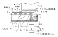
図1は本発明の記録装置の記録部要部斜視図、図2は縁なし印字による記録材裏面汚染を説明するための要部断面図(記録材搬送方向に対して垂直な断面)である。 FIG. 1 is a perspective view of a main part of a recording unit of the recording apparatus according to the present invention, and FIG. .
図中符号1はインクジェット記録ヘッド、2はインクジェット記録ヘッド1を一体的に保持するキャリッジである。 In the figure, reference numeral 1 denotes an ink jet recording head, and 2 denotes a carriage that integrally holds the ink jet recording head 1.
キャリッジ2は、不図示のモータとモータからの動力伝達ベルトにより主走査方向(図中矢印A方向)に往復動作を行う構成となっている。 The carriage 2 is configured to reciprocate in the main scanning direction (the direction of arrow A in the figure) by a motor (not shown) and a power transmission belt from the motor.
3はインクジェット記録ヘッド1に対向する位置に設置されたプラテンであり、図中矢印B方向に搬送される記録材4搬を支持する、主走査方向に複数設けられたプラテンリブ3aと該プラテンリブ3a上に設けられた記録材4を吸引する吸引口3bを備える。
吸引口3bによりローラ等の不図示の記録材搬送手段で搬送された記録紙等の記録材4をプラテンリブ3a上にエア吸着し、記録面4aを平坦にすることで安定的に高品位なインクジェット記録が行えるようになっている。
A recording material 4 such as a recording sheet conveyed by a recording material conveying means (not shown) such as a roller is sucked onto the
また、記録面4aはインクジェット記録ヘッド1と微細な距離を保持しつつ対向するように構成されている。
The
5はキャリッジ2をガイドし主走査方向に往復させるためのガイドバー、6はプラテン3の両端部に設けられた吐出インク打ち捨て用の穴でありエア吸引用の吸引口6aをその下部に有している。
5 is a guide bar for guiding the carriage 2 to reciprocate in the main scanning direction, and 6 is a hole for discarding ejected ink provided at both ends of the
また、図2に示されるように吸引口3bと6aは連通している。
Further, as shown in FIG. 2, the
7はプラテン3のユニットケース、8はインクジェット記録ヘッド1から吐出されたインク滴、9はエア吸引のためのファンであり、ユニットケース7の穴部7aより吸引ダクト10を介して接続されている。
7 is a unit case of the
11はインク廃液回収ボックスであり、ダクト12によりファン9と接続している。13はファン9により外部への排気を行うためのダクトである。 An ink waste liquid recovery box 11 is connected to the fan 9 by a duct 12. Reference numeral 13 denotes a duct for exhausting air to the outside by the fan 9.
印字時にはファン9を動作させており、記録材4をプラテン3に吸着すると同時に、穴6aより常時空気吸引を行っている。ここで吸引された空気はダクト10、ファン9、ダクト13を通り、機外に排出される。
During printing, the fan 9 is operated, and the recording material 4 is adsorbed to the
また、後に詳述するが、インク滴8を吸引したときにはダクト10、ファン9、ダクト12を通りインク廃液回収ボックス11に回収される。
As will be described in detail later, when the ink droplet 8 is sucked, it passes through the
次に縁なし印字動作について説明する。 Next, a borderless printing operation will be described.
印字時には図2に示されるように記録材4がプラテンリブ3aに吸着された状態においては記録材4が、その端部が穴6上に張り出した状態でプラテン3を完全に覆う。
At the time of printing, as shown in FIG. 2, when the recording material 4 is adsorbed to the
そして、このような状態で印字を行うことにより、プラテン3をインク滴8で汚染することなく、縁なし印字を行うことができる構成とされている。
By performing printing in such a state, the borderless printing can be performed without contaminating the
また、インクジェット記録ヘッド1が記録材4の端部、つまり、穴6上において印字動作を行うと、インクジェット記録ヘッド1がインク滴8を吐出する。
Further, when the ink jet recording head 1 performs a printing operation on the end portion of the recording material 4, that is, on the
このことにより記録材4の端部まで印字を行う、いわゆる縁なし印字を行うことができる。またこのとき記録材4の端部より外側に吐出されたインク滴8が穴6内に打ち捨てられる。
This enables so-called borderless printing in which printing is performed up to the end of the recording material 4. At this time, the ink droplets 8 ejected outside the end of the recording material 4 are discarded into the
そして、図2中の矢印Cに示されるように、穴6の下部に設けられた吸引口6aより吸引される。
Then, as indicated by an arrow C in FIG. 2, suction is performed from a
この後、ユニットケース7の穴7a、ダクト10、ファン9、ダクト12を通ってインク廃液回収ボックス11に回収され、吸引された空気はダクト10、ファン9、ダクト13を通り機外へ排出される。
Thereafter, the ink is recovered in the ink waste liquid recovery box 11 through the
ここで空気とインク滴8の分離は不図示のエアフィルタ等の公知の方法で行われている。 Here, separation of the air and the ink droplet 8 is performed by a known method such as an air filter (not shown).
ところで、縁なし印字時に打ち捨てられたインク滴8の一部が霧状インクとなる現象が確認されている。 Incidentally, it has been confirmed that a part of the ink droplets 8 discarded during borderless printing becomes mist ink.
この霧状インクの大部分は図2中の矢印Cに示されるように穴6aに吸引されるが、霧状インクの一部は図中矢印Dに示されるように吐出インク打ち捨て用の穴6に隣接するプラテンリブ3a上に設けられた吸引口3bに引き込まれる。
Most of the mist-like ink is sucked into the
吸引口3bに引き込まれた霧状インクは、記録材4端部の印刷裏面に付着しやすい傾向がある。この現象が顕著となると縁なし印字時に記録材の裏面端部が吐出インクにより汚れて記録材4の品位が低下してしまう。
The mist ink drawn into the
このため本発明においては、プラテンリブ3aの形状を霧状インクが侵入しにくいものにして記録材4端部の印刷裏面にインクで汚れる現象を抑制することにより印刷済み記録材4の品位を向上させている。
For this reason, in the present invention, the quality of the printed recording material 4 is improved by making the shape of the
プラテンリブ3aの具体的な形状は以下の実施例において説明する。
The specific shape of the
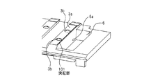
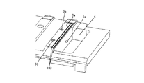
(第1の実施例)
図3は本発明の第1の実施例を示す記録装置のプラテンリブ3aの形状を示す斜視図である。吸引口3bは、空気を導入するための凹部である空気導入凹部を備え、プラテンリブ3a上での径が大きな形状とされている。
(First embodiment)
FIG. 3 is a perspective view showing the shape of the
図中符号101はプラテンリブ3a上に設けられた記録材4搬送方向(矢印B)へ延びる突起部であり、プラテンリブ3aの吐出インク打ち捨て用の穴6側に設けられている。
そしてこの突起部101が縁なし印字時に発生する霧状のインクをプラテンリブ3a上の吸引口3bに引き込むことを抑制している。
The
突起部101が形成されることにより、プラテンリブ3aは、被吸引口3b中心を通る記録材4の搬送方向を軸として非対称形状となっている。
By forming the
次に、この効果について詳述する。霧状のインクが吸引口3bに引き込まれる現象の抑制には、穴6に隣接するプラテンリブ3a方向への吸引圧を増大させて記録材4とプラテンリブ3aの接触圧力を大きくすることで大きな効果が得られる。
Next, this effect will be described in detail. In order to suppress the phenomenon in which the mist-like ink is drawn into the
しかし、各プラテンリブ3a間にて記録材4の吸引力に差が生じ、記録材4と各プラテンリブ3a間の摩擦力に差が生じた場合には、搬送される記録材4にしわが寄ってしまったり、その搬送方向が本来の方向(図2中の矢印B)からずれる懸念がある。
However, if there is a difference in the suction force of the recording material 4 between the
また、すべてのプラテンリブ3aにおいて、記録材4の吸引圧を増大させると、プラテンリブ3a全体と記録材4間の摩擦力が大きくなり、記録材4の搬送そのものに支障をきたす恐れがある。
Further, when the suction pressure of the recording material 4 is increased in all the
このため、本実施例においては先に説明したようにプラテンリブ3a上に突起部101を設けている。これにより、主走査方向寸法が小さい突起部101と記録材4の接触圧を増加させて密着させることを、記録材4との摩擦力を増大することなく行っている。
For this reason, in this embodiment, as described above, the
つまり、突起部101が設置されたプラテンリブ3aと記録材4のトータルの密着力を増大させることなく、前述の霧状インクがプラテンリブ3a上の吸引口3bに引き込まれることを抑制している。
That is, the above-described mist-like ink is suppressed from being drawn into the
このことにより記録材4の搬送に支障を来たすことなく、記録材4の印刷裏面とプラテン3が縁なし印字時に発生する霧状インクにより汚れるのを防止する効果を得ているのである。
As a result, there is an effect of preventing the printing back surface of the recording material 4 and the
また、突起部101主走査方向の幅の最大寸法は、同方向のプラテンリブ3a主走査方向幅の最大寸法の50%以下であれば、霧状のインクをプラテンリブ3a上の吸引口3bに引き込むことを抑制する効果が顕著であることが実験で証明されている。
Further, when the maximum dimension of the width in the main scanning direction of the
また、突起部101の形状について図4、図5、図6を用いて説明する。図4、図5、図6は本発明の第1の実施例を示す記録装置の突起部101の形状を示す斜視図である。
Further, the shape of the
図4において突起部101aはその主走査方向断面形状が台形形状をしている。このことにより記録材4の搬送時に突起部101aに記録材4が引っかかりにくくなる。 In FIG. 4, the protrusion 101a has a trapezoidal cross section in the main scanning direction. This makes it difficult for the recording material 4 to be caught by the protrusion 101a when the recording material 4 is conveyed.
また、突起部101aと記録材4の接触面積が小さくなり、接触圧が大きくなるため、記録材4が突起部101aに密着し、霧状のインクをプラテンリブ3a上の吸引口3bに引き込みにくくなる。
Further, since the contact area between the protrusion 101a and the recording material 4 is reduced and the contact pressure is increased, the recording material 4 is in close contact with the protrusion 101a, and it becomes difficult to draw the mist-like ink into the
つまり、記録材4の副操作方向への搬送を円滑に行いつつ、効率的に霧状のインクをプラテンリブ3a上の吸引口3bに引き込むことを抑制することが可能となる。
That is, it is possible to suppress the ink droplets from being efficiently drawn into the
ここで突起部101aの稜線の一部にコーナーRが設けられても良いことは言うまでもない。 Needless to say, the corner R may be provided at a part of the ridge line of the protrusion 101a.
また、図5に示される突起部101bは、その主走査方向断面形状が半円形状をしている。このため、図4に示される突起部101aと同様に記録材4の搬送時に突起部101bに記録材4が引っかかりにくいものとなっている。 The protrusion 101b shown in FIG. 5 has a semicircular cross section in the main scanning direction. For this reason, like the protrusion 101a shown in FIG. 4, the recording material 4 is not easily caught by the protrusion 101b when the recording material 4 is conveyed.
また、突起部101bと記録材4の接触面積が小さくなり、接触圧が大きくなるため、記録材4が突起部101bに密着し、霧状のインクをプラテンリブ3a上の吸引口3bに引き込みにくくなる。
Further, since the contact area between the projection 101b and the recording material 4 is reduced and the contact pressure is increased, the recording material 4 is in close contact with the projection 101b, and it becomes difficult to draw the mist ink into the
つまり、記録材4の副操作方向への搬送を円滑に行いつつ、効率的に霧状のインクをプラテンリブ3a上の吸引口3bに引き込むことを抑制することが可能となる。
That is, it is possible to suppress the ink droplets from being efficiently drawn into the
また、図6によれば突起部101cはその主走査方向断面が三角形形状をしており、かつ記録材4との接触部分101dが鋭角に形成されている。
Further, according to FIG. 6, the
このため、突起部101cと記録材4の接触面積が小さくなり、接触圧が大きくなるため、記録材4が接触部分101dに密着し、霧状のインクをプラテンリブ3a上の吸引口3bに引き込みにくくなる。
For this reason, the contact area between the
つまり、記録材4と突起部101cとの摩擦力を増大させることがないため、記録材4の副操作方向への搬送を円滑に行いつつ、効率的に霧状のインクをプラテンリブ3a上の吸引口3bに引き込むことを抑制することが可能となる。
That is, since the frictional force between the recording material 4 and the
また、この突起部101は穴6に隣接していないプラテンリブ3a上に設けられても良い。
Further, the
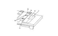
(第2の実施例)
図7は本発明の第2の実施例を示す記録装置のプラテンリブ3aの形状を示す斜視図である。
(Second embodiment)
FIG. 7 is a perspective view showing the shape of the
図7中、符号102はプラテンリブ3a上に設けられた吸引口3bとつながる溝部であり、インク打ち捨て用の穴6の反対側、且つ記録材4搬送方向(矢印B)と直行する方向に設けられている。
In FIG. 7,
この溝部102があることにより、縁なし印字時に発生する霧状のインクをプラテンリブ3a上の吸引口3bに引き込むことを抑制している。
Due to the presence of the
本実施例の効果は第1の実施例とほぼ同様であるが、本実施例においてはプラテンリブ3a上に吸引口3bとつながる溝部102を設けることで、インク打ち捨て用の穴6の反対側に存在する霧状のインクを含まない空気が溝部を通って吸引されやすくなる。
The effect of this embodiment is almost the same as that of the first embodiment, but in this embodiment, the
このことにより、溝部102が設けられたプラテンリブ3aと記録材4の密着力を増大させることなく、前述の霧状インクがプラテンリブ3a上の吸引口3bに引き込まれることを抑制できる。
Accordingly, the above-described mist ink can be prevented from being drawn into the
このことにより第1の実施例と同様に記録材4の搬送に支障をきたすことなく、記録材4の印刷裏面とプラテン3が縁なし印字時に発生する霧状インクにより汚れるのを防止する効果を得ている。
As a result, as in the first embodiment, there is an effect of preventing the printing back surface of the recording material 4 and the
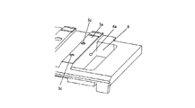
(第3の実施例)
図8は本発明の第3の実施例を示す記録装置のプラテンリブ3aの形状を示す斜視図である。
(Third embodiment)
FIG. 8 is a perspective view showing the shape of the
図中符号3cはプラテンリブ3a上に設けられた吸引口であり、吸引口3cは、その中心がプラテンリブ3aの記録材4搬送方向(矢印B)の中心よりもインク打ち捨て用の穴6の反対側に位置するように配置されている。
In the figure,
上記の配置により、インク打ち捨て用の穴6側よりもその反対側から空気を吸引しやすくなり、溝部が設けられたプラテンリブ3aと記録材4の密着力を増大させることなく前述の霧状インクが吸引口3cに引き込まれることを抑制できるものである。
With the above arrangement, it becomes easier to suck air from the opposite side than the
このことにより第1および第2の実施例と同様に記録材4の搬送に支障をきたすことなく、記録材4の印刷裏面とプラテン3が縁なし印字時に発生する霧状インクにより汚れるのを防止する効果を得ているのである。
This prevents the printing back surface of the recording material 4 and the
(第4の実施例)
図9は本発明の第4の実施例を示す記録装置のプラテンリブ3aの形状を示す斜視図である。
(Fourth embodiment)
FIG. 9 is a perspective view showing the shape of the
図中、符号103はプラテンリブ3a上に設けられた記録材4搬送方向(矢印B)へ延びる複数設けられた溝部であり、プラテンリブ3aの吐出インク打ち捨て用の穴6側に設けられている。溝部103が複数であることにより、溝部103間に凹部が形成される。
In the figure,
溝部103は少なくとも1つの溝から構成されており、記録材4と溝部103を有するプラテンリブ3aとの間は公知のラビリンス流路を形成し、インク打ち捨て用の穴6側から吸引口3bへの空気の流れを阻害する効果を生じさせる。
The
このため、溝部103が設けられたプラテンリブ3aと記録材4の密着力を増大させることなく前述の霧状インクがプラテンリブ3a上の吸引口3bに引き込まれることを抑制できるものである。
Therefore, it is possible to suppress the above-described mist ink from being drawn into the
このことにより第1ないし第3の実施例と同様に記録材4の搬送に支障をきたすことなく、記録材4の印刷裏面とプラテン3が縁なし印字時に発生する霧状インクにより汚れるのを防止する効果を得ているのである。
This prevents the printing back surface of the recording material 4 and the
また、本実施例において溝部103は2本配設されているが、溝部103は3本以上でも良いことは言うまでもない。
In this embodiment, two
1 インクジェット記録ヘッド
2 キャリッジ
3 プラテン
3a プラテンリブ
3b 吸引口
4 記録材
5 ガイドバー
6 穴
6a 吸引口
7 ユニットケース
7a穴部
8 インク滴
9 ファン
10 吸引ダクト
11 インク廃液回収ボックス
12 ダクト
13 ダクト
101 突起部
101a 突起部
101b 突起部
101c 突起部
101d 接触部分
102 溝部
103 溝部
DESCRIPTION OF SYMBOLS 1 Inkjet recording head 2
Claims (6)
記録ヘッドと、前記記録ヘッドと対向する位置に設けられ搬送される前記記録材を支持するプラテン部とを有し、前記プラテン部には複数のリブが前記記録材が搬送される方向と交差する方向に間隔をもって形成され、且つ、前記複数のリブのうち少なくとも1つの所定のリブの上に前記記録材を吸引する吸引口および当該リブよりも小さい突起部が前記記録材が搬送される方向に沿って形成され、
前記記録ヘッドから吐出され前記記録材から外れたインク滴が捨てられる穴が前記プラテン部に設けられており、前記所定のリブは前記穴に隣接しており、且つ前記突起部は前記所定のリブの上で前記吸引口よりも隣接する前記穴に近い側に形成されていることを特徴とする記録装置。 In an ink jet recording apparatus that performs recording by discharging ink droplets onto a recording material,
A recording head; and a platen portion that is provided at a position facing the recording head and supports the recording material that is conveyed, and a plurality of ribs intersect the direction in which the recording material is conveyed in the platen portion. A suction port for sucking the recording material on at least one predetermined rib among the plurality of ribs and a protrusion smaller than the rib are formed in a direction in which the recording material is conveyed. Formed along
A hole for discarding ink droplets ejected from the recording head and removed from the recording material is provided in the platen portion, the predetermined rib is adjacent to the hole, and the protrusion is the predetermined rib. The recording apparatus is formed on the side closer to the hole adjacent to the suction port.
記録ヘッドと、前記記録ヘッドと対向する位置に設けられ搬送される前記記録材を支持するプラテン部とを有し、前記プラテン部には複数のリブが前記記録材が搬送される方向と交差する方向に間隔をもって形成され、且つ、前記複数のリブのうち少なくとも1つの所定のリブの上に前記記録材を吸引する吸引口および該吸引口とつながる溝部が形成され、
前記記録ヘッドから吐出され前記記録材から外れたインク滴が捨てられる穴が前記プラテン部に設けられており、前記溝部は前記所定のリブの上における、前記穴とは反対側の縁にまで延びていることを特徴とする記録装置。 In an ink jet recording apparatus that performs recording by discharging ink droplets onto a recording material,
A recording head; and a platen portion that is provided at a position facing the recording head and supports the recording material that is conveyed, and a plurality of ribs intersect the direction in which the recording material is conveyed in the platen portion. A suction port for sucking the recording material and a groove connected to the suction port are formed on at least one predetermined rib among the plurality of ribs;
Wherein which ink droplets out from the recording medium ejected from the recording head holes are discarded provided in the platen unit, the groove is definitive on the predetermined rib extends to the opposite edge and the hole recording apparatus characterized by being.
Priority Applications (1)
| Application Number | Priority Date | Filing Date | Title |
|---|---|---|---|
| JP2007297922A JP5142679B2 (en) | 2007-11-16 | 2007-11-16 | Recording device |
Applications Claiming Priority (1)
| Application Number | Priority Date | Filing Date | Title |
|---|---|---|---|
| JP2007297922A JP5142679B2 (en) | 2007-11-16 | 2007-11-16 | Recording device |
Publications (3)
| Publication Number | Publication Date |
|---|---|
| JP2009119778A JP2009119778A (en) | 2009-06-04 |
| JP2009119778A5 JP2009119778A5 (en) | 2011-01-13 |
| JP5142679B2 true JP5142679B2 (en) | 2013-02-13 |
Family
ID=40812471
Family Applications (1)
| Application Number | Title | Priority Date | Filing Date |
|---|---|---|---|
| JP2007297922A Expired - Fee Related JP5142679B2 (en) | 2007-11-16 | 2007-11-16 | Recording device |
Country Status (1)
| Country | Link |
|---|---|
| JP (1) | JP5142679B2 (en) |
Families Citing this family (9)
| Publication number | Priority date | Publication date | Assignee | Title |
|---|---|---|---|---|
| JP5733488B2 (en) | 2009-09-25 | 2015-06-10 | セイコーエプソン株式会社 | Recording device |
| JP5494951B2 (en) * | 2010-03-12 | 2014-05-21 | セイコーエプソン株式会社 | Liquid ejector |
| US10624275B1 (en) | 2010-03-23 | 2020-04-21 | Myles D. Lewis | Semi-automated crop production system |
| JP5974521B2 (en) | 2012-02-09 | 2016-08-23 | セイコーエプソン株式会社 | Liquid ejector |
| JP5929285B2 (en) | 2012-02-14 | 2016-06-01 | セイコーエプソン株式会社 | Liquid ejector |
| JP5987362B2 (en) | 2012-03-02 | 2016-09-07 | セイコーエプソン株式会社 | Liquid ejector |
| JP2015080927A (en) * | 2013-10-24 | 2015-04-27 | セイコーエプソン株式会社 | Droplet discharge device |
| JP6476641B2 (en) | 2014-08-08 | 2019-03-06 | セイコーエプソン株式会社 | Printing device |
| JP6565227B2 (en) * | 2015-03-06 | 2019-08-28 | セイコーエプソン株式会社 | Recording device |
Family Cites Families (3)
| Publication number | Priority date | Publication date | Assignee | Title |
|---|---|---|---|---|
| JP2006192843A (en) * | 2005-01-17 | 2006-07-27 | Seiko Epson Corp | Platen, recorder with platen, and liquid injection apparatus with platen |
| JP2006224507A (en) * | 2005-02-18 | 2006-08-31 | Seiko Epson Corp | Liquid jet device and recording device |
| JP2007144825A (en) * | 2005-11-29 | 2007-06-14 | Canon Inc | Inkjet recorder |
-
2007
- 2007-11-16 JP JP2007297922A patent/JP5142679B2/en not_active Expired - Fee Related
Also Published As
| Publication number | Publication date |
|---|---|
| JP2009119778A (en) | 2009-06-04 |
Similar Documents
| Publication | Publication Date | Title |
|---|---|---|
| JP5142679B2 (en) | Recording device | |
| JP4500227B2 (en) | Paper transport mechanism | |
| JP4785634B2 (en) | Inkjet recording device | |
| US20070291096A1 (en) | Inkjet recording apparatus | |
| JP4850593B2 (en) | Inkjet recording device | |
| JP5106222B2 (en) | Inkjet recording device | |
| JP2006231612A (en) | Inkjet recording device | |
| JP2007144825A (en) | Inkjet recorder | |
| JP2007331283A (en) | Inkjet recording apparatus | |
| JP2010017895A (en) | Inkjet recorder | |
| JP2005205766A (en) | Inkjet recording apparatus | |
| JP6525836B2 (en) | Printing device | |
| US11685159B2 (en) | Platen assembly for sheet fed printer | |
| JP2008229966A (en) | Inkjet recording device | |
| JP2009291982A (en) | Inkjet recording apparatus | |
| JP2009292108A (en) | Inkjet recorder | |
| JP5637733B2 (en) | Inkjet recording device | |
| EP1419890B1 (en) | Vacuum platen assembly for fluid-ejection device | |
| JP2004284184A (en) | Ink jet recorder | |
| JP5621556B2 (en) | Platen and image recording apparatus | |
| JP2002144650A (en) | Ink jet recording apparatus | |
| JP4123984B2 (en) | RECORDING MEDIUM CONVEYING DEVICE AND RECORDING DEVICE | |
| JP2005199465A (en) | Image forming apparatus | |
| JP2005125610A (en) | Printer |
Legal Events
| Date | Code | Title | Description |
|---|---|---|---|
| A521 | Written amendment |
Free format text: JAPANESE INTERMEDIATE CODE: A523 Effective date: 20101116 |
|
| A621 | Written request for application examination |
Free format text: JAPANESE INTERMEDIATE CODE: A621 Effective date: 20101116 |
|
| A977 | Report on retrieval |
Free format text: JAPANESE INTERMEDIATE CODE: A971007 Effective date: 20120419 |
|
| A131 | Notification of reasons for refusal |
Free format text: JAPANESE INTERMEDIATE CODE: A131 Effective date: 20120424 |
|
| A521 | Written amendment |
Free format text: JAPANESE INTERMEDIATE CODE: A523 Effective date: 20120620 |
|
| A131 | Notification of reasons for refusal |
Free format text: JAPANESE INTERMEDIATE CODE: A131 Effective date: 20120710 |
|
| A521 | Written amendment |
Free format text: JAPANESE INTERMEDIATE CODE: A523 Effective date: 20120907 |
|
| TRDD | Decision of grant or rejection written | ||
| A01 | Written decision to grant a patent or to grant a registration (utility model) |
Free format text: JAPANESE INTERMEDIATE CODE: A01 Effective date: 20121023 |
|
| A01 | Written decision to grant a patent or to grant a registration (utility model) |
Free format text: JAPANESE INTERMEDIATE CODE: A01 |
|
| A61 | First payment of annual fees (during grant procedure) |
Free format text: JAPANESE INTERMEDIATE CODE: A61 Effective date: 20121120 |
|
| FPAY | Renewal fee payment (event date is renewal date of database) |
Free format text: PAYMENT UNTIL: 20151130 Year of fee payment: 3 |
|
| R151 | Written notification of patent or utility model registration |
Ref document number: 5142679 Country of ref document: JP Free format text: JAPANESE INTERMEDIATE CODE: R151 |
|
| LAPS | Cancellation because of no payment of annual fees |