EP1418371A1 - Joint dynamique pour arbre rotatif muni d'un dispositif de codage angulaire, dispositif comportant un tel joint et procédé de fabrication d'un tel joint - Google Patents
Joint dynamique pour arbre rotatif muni d'un dispositif de codage angulaire, dispositif comportant un tel joint et procédé de fabrication d'un tel joint Download PDFInfo
- Publication number
- EP1418371A1 EP1418371A1 EP20030292548 EP03292548A EP1418371A1 EP 1418371 A1 EP1418371 A1 EP 1418371A1 EP 20030292548 EP20030292548 EP 20030292548 EP 03292548 A EP03292548 A EP 03292548A EP 1418371 A1 EP1418371 A1 EP 1418371A1
- Authority
- EP
- European Patent Office
- Prior art keywords
- sleeve
- lip
- shaft
- encoder element
- annular
- Prior art date
- Legal status (The legal status is an assumption and is not a legal conclusion. Google has not performed a legal analysis and makes no representation as to the accuracy of the status listed.)
- Granted
Links
- 238000004519 manufacturing process Methods 0.000 title claims abstract description 9
- 238000007789 sealing Methods 0.000 title claims description 10
- 229920000642 polymer Polymers 0.000 claims abstract description 10
- 229920001343 polytetrafluoroethylene Polymers 0.000 claims description 11
- 239000004810 polytetrafluoroethylene Substances 0.000 claims description 11
- 238000007731 hot pressing Methods 0.000 claims description 3
- 239000007788 liquid Substances 0.000 claims description 2
- 239000002184 metal Substances 0.000 description 4
- 238000000034 method Methods 0.000 description 4
- 238000002485 combustion reaction Methods 0.000 description 3
- 230000000694 effects Effects 0.000 description 2
- 239000011248 coating agent Substances 0.000 description 1
- 238000000576 coating method Methods 0.000 description 1
- 239000000470 constituent Substances 0.000 description 1
- 229920001971 elastomer Polymers 0.000 description 1
- 239000000806 elastomer Substances 0.000 description 1
- 238000002347 injection Methods 0.000 description 1
- 239000007924 injection Substances 0.000 description 1
- 239000000463 material Substances 0.000 description 1
- 239000002245 particle Substances 0.000 description 1
- 239000004033 plastic Substances 0.000 description 1
- -1 polytetrafluoroethylene Polymers 0.000 description 1
- 238000003825 pressing Methods 0.000 description 1
- 238000001356 surgical procedure Methods 0.000 description 1
- 238000004073 vulcanization Methods 0.000 description 1
- 229910000859 α-Fe Inorganic materials 0.000 description 1
Images



Classifications
-
- F—MECHANICAL ENGINEERING; LIGHTING; HEATING; WEAPONS; BLASTING
- F16—ENGINEERING ELEMENTS AND UNITS; GENERAL MEASURES FOR PRODUCING AND MAINTAINING EFFECTIVE FUNCTIONING OF MACHINES OR INSTALLATIONS; THERMAL INSULATION IN GENERAL
- F16J—PISTONS; CYLINDERS; SEALINGS
- F16J15/00—Sealings
- F16J15/16—Sealings between relatively-moving surfaces
- F16J15/164—Sealings between relatively-moving surfaces the sealing action depending on movements; pressure difference, temperature or presence of leaking fluid
-
- F—MECHANICAL ENGINEERING; LIGHTING; HEATING; WEAPONS; BLASTING
- F16—ENGINEERING ELEMENTS AND UNITS; GENERAL MEASURES FOR PRODUCING AND MAINTAINING EFFECTIVE FUNCTIONING OF MACHINES OR INSTALLATIONS; THERMAL INSULATION IN GENERAL
- F16J—PISTONS; CYLINDERS; SEALINGS
- F16J15/00—Sealings
- F16J15/16—Sealings between relatively-moving surfaces
- F16J15/32—Sealings between relatively-moving surfaces with elastic sealings, e.g. O-rings
- F16J15/3204—Sealings between relatively-moving surfaces with elastic sealings, e.g. O-rings with at least one lip
- F16J15/3228—Sealings between relatively-moving surfaces with elastic sealings, e.g. O-rings with at least one lip formed by deforming a flat ring
-
- F—MECHANICAL ENGINEERING; LIGHTING; HEATING; WEAPONS; BLASTING
- F16—ENGINEERING ELEMENTS AND UNITS; GENERAL MEASURES FOR PRODUCING AND MAINTAINING EFFECTIVE FUNCTIONING OF MACHINES OR INSTALLATIONS; THERMAL INSULATION IN GENERAL
- F16J—PISTONS; CYLINDERS; SEALINGS
- F16J15/00—Sealings
- F16J15/16—Sealings between relatively-moving surfaces
- F16J15/32—Sealings between relatively-moving surfaces with elastic sealings, e.g. O-rings
- F16J15/3248—Sealings between relatively-moving surfaces with elastic sealings, e.g. O-rings provided with casings or supports
- F16J15/3252—Sealings between relatively-moving surfaces with elastic sealings, e.g. O-rings provided with casings or supports with rigid casings or supports
- F16J15/3256—Sealings between relatively-moving surfaces with elastic sealings, e.g. O-rings provided with casings or supports with rigid casings or supports comprising two casing or support elements, one attached to each surface, e.g. cartridge or cassette seals
- F16J15/326—Sealings between relatively-moving surfaces with elastic sealings, e.g. O-rings provided with casings or supports with rigid casings or supports comprising two casing or support elements, one attached to each surface, e.g. cartridge or cassette seals with means for detecting or measuring relative rotation of the two elements
-
- G—PHYSICS
- G01—MEASURING; TESTING
- G01P—MEASURING LINEAR OR ANGULAR SPEED, ACCELERATION, DECELERATION, OR SHOCK; INDICATING PRESENCE, ABSENCE, OR DIRECTION, OF MOVEMENT
- G01P3/00—Measuring linear or angular speed; Measuring differences of linear or angular speeds
- G01P3/42—Devices characterised by the use of electric or magnetic means
- G01P3/44—Devices characterised by the use of electric or magnetic means for measuring angular speed
- G01P3/443—Devices characterised by the use of electric or magnetic means for measuring angular speed mounted in bearings
Definitions
- the present invention relates to a dynamic joint for a rotary shaft comprising a sleeve intended to be wedged in rotation on the shaft, and an annular lip in low coefficient of friction polymer intended to come in sliding rotary contact with a fixed casing surrounding the shaft, so that the dynamic seal ensures the seal between said shaft and said housing.
- the invention relates more particularly to such gasket equipped with an angular coding device.
- the present invention aims to overcome these disadvantages by proposing a dynamic seal ensuring the angular encoding of the shaft and which can be mounted easily in one operation.
- a dynamic seal ensuring the angular encoding of the shaft and which can be mounted easily in one operation.
- the size and cost of manufacturing this device must remain as small as possible.
- the subject of the present invention is a dynamic joint as defined above characterized in what a magnetizable polymer annular encoder element and having at least one polarized mark, is integral of said sleeve and has at least one annular surface on which is adhered said lip.
- This unitary assembly can easily be mounted in a single operation, for example by fitting the sleeve on the rotating shaft.
- the subject of the invention is also a device comprising a rotary shaft, a housing filled with liquid into which the rotary shaft penetrates, and a seal dynamic as previously defined whose sleeve is rotated relative to the rotary shaft and whose sealing lip is in sliding contact with the housing, by sealing between said shaft and said housing.
- the seal dynamic 1 comprises a sleeve 2 set in rotation on a rotary shaft 3 and an annular sealing lip 4 coming into rotating sliding contact with a fixed housing 5 surrounding the shaft 3, so as to ensure the tightness between said shaft and said housing.
- the shaft 3 may be constituted by the crankshaft of an internal combustion engine which contains hot oil under pressure in an interior space H delimited by the fixed housing 5.
- the dynamic seal shown can be mounted on all types of rotary shafts, such as a gearbox output shaft.
- the sleeve 2 is metallic and is mounted on the rotary shaft 3 by press fit. This montage particularly simple makes it possible to immobilize the sleeve 2 in rotation and in translation with respect to the tree 3. But we can use any other assembly that ensures a immobilization in rotation of the sleeve with respect to the tree. It is also possible to use a plastic sleeve.
- the annular lip 4 is made of a polymer with a low coefficient of friction, and preferably of PTFE (polytetrafluoroethylene), in order to limit the temperature rise due to the sliding of the lip against the wall 5a of the fixed casing 5 when the seal rotates at a high speed.
- the lip 4 comprises a base 4a extending radially with respect to the axis of rotation X of the shaft, and an end 4b which has a certain flexibility and which is bent towards the inside of the housing 5 under the effect of the contact with the fixed part of the housing to fit perfectly the wall 5a of the housing.
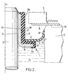
- the end can also be bent out of the housing as shown for example in Figure 2, and may include grooves 4c to improve the seal.
- An annular encoder element 6 made of polymer magnetizable is integral with the sleeve 2 and forms a support surface on which the lip 4 is adhered.
- the annular encoder element 6 has at least one polarized mark so that the movement of rotation of the shaft 3 can be detected during the passage polarized mark before a sensor 7 placed near the the encoder element 6.
- An effect sensor can be used hall or any other type of sensor capable of detecting a variation of the magnetic field and able to send a electrical signal to a data processing unit as for example an electronic management box of the internal combustion engine.
- the encoder element 6 is preferably elastoferrite, that is to say an elastomer containing ferrite particles that can generate a field magnetic. Thanks to this material, we can assemble particularly simple way, for example using the process described below, the various elements of the joint dynamic. Indeed, elastoferrite which is of nature different from PTFE, can adhere directly to the sleeve metallic. In addition, elastoferrite can also adhere directly to PTFE. Thus, the encoder element forms a means fixing the PTFE lip 4 on the metal sleeve 2, while it is particularly difficult to adhere or sticking PTFE on a metal element or element having a smooth and hard surface.
- the encoder element 6 has an annular surface 10 extending radially with respect to the axis X of the shaft 3 to form the support surface on which the base 4a of the lip is bonded. .
- This annular surface 10 is obtained during the injection of molten elastoferrite into a mold in which the lip 4 has been previously arranged. Note that the lip 4 can simply be laid flat in the mold, since a simple surface contact with the elastoferrite melted enough to secure the lip 4 and the encoder element 10.
- the sleeve 2 has an annular flange 12 extending radially.
- the encoder element has a first annular face 14 extending radially relative to the axis of rotation X of the shaft 3 and a second circular face 15 parallel to the first face 14.
- the first face 14 adheres directly to the collar 12 of the sleeve and the track provided with polarized marks is formed on the second face 15.
- the sensor 7 is disposed longitudinally facing said second face 15 with a plate 8 fixed on the outer face 5b of the housing.
- the runway may comprise a set of sectors equiangular polarized alternately north-south and possibly an area forming a magnetic singularity in order to be able to determine an absolute angular position of the tree.
- the encoder element 6 presents a first annular face 17 oriented radially inwards and a second circular face 18 oriented radially towards the outside on which is formed the track provided with polarized landmarks.
- the first face 17 adheres directly on an outer wall 19 of the sleeve 2 which extends longitudinally along the tree 3.
- the track provided with polarized landmarks On the second side 18 of the encoder element 6 is formed the track provided with polarized landmarks.
- the sensor 7 is arranged radially opposite said track.
- the second face 18 of the encoder element 6 has a portion 18a extending along a part of the tree 3 that is not surrounded by the fixed housing 5 and on which is formed the track provided polarized landmarks.
- the sensor 7 can be mounted on the outer face 5b of the fixed casing, possibly to using an intermediate stage 8.
- the metal sleeve 2 has a section transverse U-shaped; a first branch 20 of the U is force-fitted on the rotary shaft 3, while the second branch 21 of the U forms the outer wall of the muff.
- the first annular face 17 of the encoder element 6 adheres directly to this wall 21.
- the senor 7 is arranged in space H interior of the housing 5 containing the oil, against the wall 5a of the housing oriented radially towards the shaft 3.
- a second circular face 18 of the encoder element 6 then extends longitudinally along the shaft 3 from the inside of lip 4 and includes a track provided with polarized marks which is arranged opposite of the sensor 7.
- the present invention also relates to a method for of manufacturing the dynamic seal previously described. According to this manufacturing process, concentrically in a first half-mold the sleeve 2, a blank of said encoder element 6 and a preform of the PTFE lip 4 of in such a way that the roughing of the coding element 6 is at least partially in contact with the sleeve 2 and that the preform of lip 4 is at least partially in contact with the blank. Then we do a pressing at warm using a second half-mold so as to vulcanize the draft in elastoferrite.
- Vulcanization of the blank of the encoder element 6 allows to obtain its adhesion to the metal sleeve 2 and its adhesion with the base 4a of the PTFE lip.
- Hot pressing also helps to comply the blank of the encoder element 6 and the lip preform 4, which can be simple washers, to get their definitive form.
- the creep of elastoferrite under the action of pressure and heat allows in particular to obtain the flange 6a which overmould the sleeve 2.
- the definitive profile of the tip 4b of the lip and in particular the groove 4c can be obtained during manufacturing process previously described and their role is to improve the tightness of the contact of the lip 4 with the housing 5.
- This process makes it possible to assemble the different constituent elements of the joint 1 and get the form definitive of the coding element 6 of the lip 4 in a single surgery.
- the dynamic joint object of the invention may be manufactured according to different.
- the encoder element can be interlocked in particular with the sleeve using mechanical fasteners and the polymer lip can be glued to the element encoder which is itself in polymer.
Landscapes
- Engineering & Computer Science (AREA)
- General Engineering & Computer Science (AREA)
- Mechanical Engineering (AREA)
- Physics & Mathematics (AREA)
- General Physics & Mathematics (AREA)
- Sealing With Elastic Sealing Lips (AREA)
- Transmission And Conversion Of Sensor Element Output (AREA)
- Sealing Devices (AREA)
- Pressure Welding/Diffusion-Bonding (AREA)
Abstract
Description
- soit deux opérations de montage, ce qui oblige l'opérateur à vérifier que les éléments sont bien disposés l'un par rapport à l'autre ;
- soit l'utilisation d'un outillage complexe permettant le montage simultané des deux éléments.
- l'élément codeur est de l'élastoferrite ;
- la lèvre est du PTFE ;
- la lèvre adhère directement sur l'élément codeur ;
- la surface annulaire de l'élément codeur s'étend radialement ;
- l'élément codeur adhère directement sur le manchon, ledit manchon étant métallique ;
- l'élément codeur présente une piste circulaire munie de repères polarisés formés par des secteurs polarisés alternativement nord-sud ;
- l'élément codeur présente une première face annulaire orientée radialement vers l'intérieur qui adhère directement sur une paroi extérieure du manchon s'étendant longitudinalement, et une deuxième face circulaire orientée radialement vers l'extérieur sur laquelle est formée la piste munie des repères polarisés ;
- la deuxième face circulaire présente une portion s'étendant le long d'une partie de l'arbre qui n'est pas entourée par le carter fixe, la piste munie des repères polarisés étant formée sur ladite portion ;
- le manchon présente une collerette annulaire s'étendant radialement tandis que l'élément codeur présente une première face annulaire s'étendant radialement qui adhère directement à ladite collerette, et une deuxième face circulaire, parallèle à la première face, sur laquelle est formée la piste munie des repères polarisés.
- en ce qu'on place concentriquement dans un premier demi-moule ledit manchon, une ébauche dudit élément codeur et une préforme de ladite lèvre, ladite ébauche étant au moins partiellement en contact avec ledit manchon et ladite préforme étant au moins partiellement en contact avec ladite ébauche ;
- et en ce qu'on effectue un pressage à chaud à l'aide d'un deuxième demi-moule pour vulcaniser ladite ébauche et pour conformer ladite ébauche de l'élément codeur et ladite préforme de la lèvre selon un profil déterminé.
- la figure 1 est une vue en coupe longitudinale simplifiée d'un arbre muni d'un joint dynamique selon un premier mode de réalisation de l'invention ;
- la figure 2 est une vue analogue à la figure 1 d'un deuxième mode de réalisation ;
- la figure 3 est une vue analogue à la figure 1 d'un troisième mode de réalisation ;
- la figure 4 est une vue analogue à la figure 1 d'un quatrième mode de réalisation.
Claims (12)
- Joint dynamique pour arbre rotatif comprenant un manchon (2) destiné à être calé en rotation sur l'arbre (3), et une lèvre annulaire (4) en polymère à faible coefficient de friction destinée à venir en contact rotatif glissant avec un carter fixe (5) entourant ledit arbre, de sorte que le joint dynamique assure l'étanchéité entre ledit arbre et ledit carter, caractérisé en ce qu'un élément codeur annulaire (6) en polymère magnétisable présentant au moins un repère polarisé, est solidaire dudit manchon (2) et présente au moins une surface annulaire (10) sur laquelle est adhérisée ladite lèvre (4).
- Joint selon la revendication 1, dans lequel l'élément codeur (6) est de l'élastoferrite.
- Joint selon la revendication 1 ou 2, dans lequel la lèvre (4) est du PTFE.
- Joint selon l'une quelconque des revendications 1 à 3, dans lequel la lèvre (4) adhère directement sur l'élément codeur (6).
- Joint selon l'une quelconque des revendications 1 à 4, dans lequel la surface annulaire (10) de l'élément codeur (6) s'étend radialement.
- Joint selon l'une quelconque des revendications 1 à 5, dans lequel l'élément codeur (6) adhère directement sur le manchon (2), ledit manchon étant métallique.
- Joint selon l'une quelconque des revendications 1 à 6, dans lequel l'élément codeur (6) présente une piste circulaire munie de repères polarisés formés par des secteurs polarisés alternativement nord-sud.
- Joint selon la revendication 7, dans lequel l'élément codeur (6) présente une première face annulaire (17) orientée radialement vers l'intérieur qui adhère directement sur une paroi extérieure (19) du manchon (2) s'étendant longitudinalement, et une deuxième face circulaire (18) orientée radialement vers l'extérieur sur laquelle est formé la piste munie des repères polarisés.
- Joint selon l'une quelconque la revendication 8, dans lequel la deuxième face circulaire (18) présente une portion (18a) s'étendant le long d'une partie de l'arbre (3) qui n'est pas entourée par le carter fixe (5), la piste munie des repères polarisés étant formée sur ladite portion (18a).
- Joint selon la revendication 7, dans lequel le manchon (2) présente une collerette annulaire (12) s'étendant radialement et dans lequel l'élément codeur (6) présente une première face annulaire (14) s'étendant radialement qui adhère directement à ladite collerette (12), et une deuxième face circulaire (15), parallèle à la première face (14), sur laquelle est formée la piste munie des repères polarisés.
- Dispositif comprenant un arbre rotatif (3), un carter (5) rempli de liquide (H) dans lequel pénètre l'arbre rotatif, et un joint dynamique (1) selon l'une quelconque des revendications précédentes dont le manchon (2) est calé en rotation par rapport à l'arbre rotatif et dont la lèvre d'étanchéité (4) est en contact glissant avec le carter, en assurant l'étanchéité entre ledit arbre et ledit carter.
- Procédé de fabrication d'un joint dynamique d'étanchéité pour arbre rotatif selon l'une quelconque des revendications 1 à 10, comprenant un manchon (2), un élément codeur annulaire (6) en élastoferrite et une lèvre d'étanchéité (4) en polymère à faible coefficient de friction, caractérisé en ce que :on place concentriquement dans un premier demi-moule ledit manchon, une ébauche dudit élément codeur et une préforme de ladite lèvre, ladite ébauche étant au moins partiellement en contact avec ledit manchon et ladite préforme étant au moins partiellement en contact avec ladite ébauche ;on effectue un pressage à chaud à l'aide d'un deuxième demi-moule pour vulcaniser ladite ébauche, ainsi que pour conformer ladite ébauche de l'élément codeur et ladite préforme de la lèvre selon un profil déterminé.
Applications Claiming Priority (2)
| Application Number | Priority Date | Filing Date | Title |
|---|---|---|---|
| FR0213940 | 2002-11-07 | ||
| FR0213940A FR2847018B1 (fr) | 2002-11-07 | 2002-11-07 | Joint dynamique pour arbre rotatif muni d'un dispositif de codage angulaire, dispositif comportant un tel joint et procede de fabrication d'un tel joint |
Publications (2)
| Publication Number | Publication Date |
|---|---|
| EP1418371A1 true EP1418371A1 (fr) | 2004-05-12 |
| EP1418371B1 EP1418371B1 (fr) | 2006-07-19 |
Family
ID=32104528
Family Applications (1)
| Application Number | Title | Priority Date | Filing Date |
|---|---|---|---|
| EP03292548A Expired - Lifetime EP1418371B1 (fr) | 2002-11-07 | 2003-10-14 | Joint dynamique pour arbre rotatif muni d'un dispositif de codage angulaire, dispositif comportant un tel joint et procédé de fabrication d'un tel joint |
Country Status (6)
| Country | Link |
|---|---|
| US (1) | US7201380B2 (fr) |
| EP (1) | EP1418371B1 (fr) |
| AT (1) | ATE333613T1 (fr) |
| DE (1) | DE60306869T2 (fr) |
| FR (1) | FR2847018B1 (fr) |
| PT (1) | PT1418371E (fr) |
Cited By (2)
| Publication number | Priority date | Publication date | Assignee | Title |
|---|---|---|---|---|
| FR2898188A1 (fr) * | 2006-03-06 | 2007-09-07 | Hutchinson Sa | Codeur pour arbre, dispositif comprenant un tel codeur et procede de fabrication d'un tel codeur |
| WO2014184465A1 (fr) * | 2013-05-17 | 2014-11-20 | Hutchinson | Codeur de position |
Families Citing this family (9)
| Publication number | Priority date | Publication date | Assignee | Title |
|---|---|---|---|---|
| US7041604B2 (en) * | 2004-09-21 | 2006-05-09 | Molecular Imprints, Inc. | Method of patterning surfaces while providing greater control of recess anisotropy |
| ITTO20050088A1 (it) * | 2005-02-15 | 2006-08-16 | Rft Spa | Dispositivo di tenuta per cuscinetti con encoder integrato. |
| DE102005037568A1 (de) * | 2005-08-09 | 2007-03-15 | Federal-Mogul Sealing Systems Bretten Gmbh | Elastomer-Wellendichtring |
| US8100104B2 (en) * | 2008-06-05 | 2012-01-24 | Ford Global Technologies | Torsion lock encoder device for internal combustion engine |
| DE102010001345B4 (de) * | 2010-01-28 | 2013-09-19 | Trelleborg Sealing Solutions Germany Gmbh | Drehdurchführung |
| GB201021931D0 (en) * | 2010-12-23 | 2011-02-02 | Agco Int Gmbh | Rotary seal arrangement |
| US10322797B2 (en) * | 2015-03-03 | 2019-06-18 | Bell Helicopter Textron Inc. | Rotating sealing systems |
| US9651153B1 (en) | 2016-10-19 | 2017-05-16 | American Axle & Manufacturing, Inc. | Axle assembly and contamination self-trapping seal |
| US11773977B2 (en) * | 2020-07-08 | 2023-10-03 | Saint-Gobain Performance Plastics Corporation | Bimetallic seal |
Citations (3)
| Publication number | Priority date | Publication date | Assignee | Title |
|---|---|---|---|---|
| EP0949510A1 (fr) * | 1998-04-07 | 1999-10-13 | Hutchinson | Joint dynamique de type "casstte" à dispositif de repérage angulaire; procédé pour sa mise en oeuvre |
| EP1164318A2 (fr) * | 2000-06-13 | 2001-12-19 | Koyo Seiko Co., Ltd. | Anneau d'étanchéité, dispositif d'étanchéité et roulement à billes pourvu de celui-ci |
| DE10050983A1 (de) * | 2000-10-16 | 2002-05-02 | Freudenberg Carl Kg | Axialwellendichtung in einer Gehäusebohrung mit einem mit der Welle fest verbundenen umlaufenden Innenteil |
Family Cites Families (9)
| Publication number | Priority date | Publication date | Assignee | Title |
|---|---|---|---|---|
| FR2678691B1 (fr) * | 1991-07-05 | 1995-04-21 | Skf France | Dispositif de capteur de vitesse de rotation pour roulements et roulement equipe d'un tel dispositif. |
| US5261752A (en) * | 1991-09-12 | 1993-11-16 | Nsk Ltd. | Bearing having passive pulser ring |
| FR2710985B1 (fr) * | 1993-10-06 | 1995-11-24 | Skf France | Elément codeur pour roulement muni d'un ensemble capteur d'informations et roulement comportant un tel élément codeur. |
| US5492339A (en) * | 1994-05-17 | 1996-02-20 | General Motors Corporation | Rotary seal assembly |
| FR2730566B1 (fr) * | 1995-02-09 | 1997-06-13 | Skf France | Dispositif de codeur pour capteur de vitesse de rotation et roulement equipe d'un tel dispositif |
| JP4141588B2 (ja) * | 1999-06-02 | 2008-08-27 | 株式会社ジェイテクト | 車輪速検出装置 |
| JP4578015B2 (ja) * | 2000-05-31 | 2010-11-10 | 株式会社ジェイテクト | 密封装置ならびに軸受装置 |
| ITTO20010245A1 (it) * | 2001-03-16 | 2002-09-16 | S K F Ind S P A | Dispositivo di tenuta per cuscinetti. |
| DE10140837C1 (de) * | 2001-08-21 | 2003-06-18 | Skf Ab | Dichtungsanordnung |
-
2002
- 2002-11-07 FR FR0213940A patent/FR2847018B1/fr not_active Expired - Lifetime
-
2003
- 2003-10-14 DE DE60306869T patent/DE60306869T2/de not_active Expired - Lifetime
- 2003-10-14 AT AT03292548T patent/ATE333613T1/de not_active IP Right Cessation
- 2003-10-14 EP EP03292548A patent/EP1418371B1/fr not_active Expired - Lifetime
- 2003-10-14 PT PT03292548T patent/PT1418371E/pt unknown
- 2003-10-16 US US10/687,205 patent/US7201380B2/en not_active Expired - Fee Related
Patent Citations (3)
| Publication number | Priority date | Publication date | Assignee | Title |
|---|---|---|---|---|
| EP0949510A1 (fr) * | 1998-04-07 | 1999-10-13 | Hutchinson | Joint dynamique de type "casstte" à dispositif de repérage angulaire; procédé pour sa mise en oeuvre |
| EP1164318A2 (fr) * | 2000-06-13 | 2001-12-19 | Koyo Seiko Co., Ltd. | Anneau d'étanchéité, dispositif d'étanchéité et roulement à billes pourvu de celui-ci |
| DE10050983A1 (de) * | 2000-10-16 | 2002-05-02 | Freudenberg Carl Kg | Axialwellendichtung in einer Gehäusebohrung mit einem mit der Welle fest verbundenen umlaufenden Innenteil |
Cited By (5)
| Publication number | Priority date | Publication date | Assignee | Title |
|---|---|---|---|---|
| FR2898188A1 (fr) * | 2006-03-06 | 2007-09-07 | Hutchinson Sa | Codeur pour arbre, dispositif comprenant un tel codeur et procede de fabrication d'un tel codeur |
| EP1832852A1 (fr) * | 2006-03-06 | 2007-09-12 | Hutchinson | Codeur pour arbre, dispositif comprenant un tel codeur et procédé de fabrication d'un tel codeur. |
| US8188820B2 (en) | 2006-03-06 | 2012-05-29 | Hutchinson S.A. | Shaft encoder, device comprising such an encoder and method of manufacturing such an encoder |
| WO2014184465A1 (fr) * | 2013-05-17 | 2014-11-20 | Hutchinson | Codeur de position |
| FR3005728A1 (fr) * | 2013-05-17 | 2014-11-21 | Hutchinson | Codeur de position |
Also Published As
| Publication number | Publication date |
|---|---|
| DE60306869D1 (de) | 2006-08-31 |
| DE60306869T2 (de) | 2007-03-01 |
| US7201380B2 (en) | 2007-04-10 |
| EP1418371B1 (fr) | 2006-07-19 |
| ATE333613T1 (de) | 2006-08-15 |
| PT1418371E (pt) | 2006-12-29 |
| FR2847018A1 (fr) | 2004-05-14 |
| FR2847018B1 (fr) | 2005-02-04 |
| US20040124586A1 (en) | 2004-07-01 |
Similar Documents
| Publication | Publication Date | Title |
|---|---|---|
| EP0521789B1 (fr) | Ensemble capteur étanche intégrable dans un roulement à capteur d'informations et roulement équipé d'un tel ensemble | |
| EP0378939B1 (fr) | Joint d'étanchéité tournant à codeur magnétique intégré, notamment pour des roulements à capteurs d'informations | |
| EP1418371B1 (fr) | Joint dynamique pour arbre rotatif muni d'un dispositif de codage angulaire, dispositif comportant un tel joint et procédé de fabrication d'un tel joint | |
| EP0371836B1 (fr) | Roulement à capteur d'informations | |
| FR2642122A1 (fr) | Joint d'etancheite tournant a codeur magnetique integre, notamment pour des roulements a capteurs d'informations | |
| FR2625280A1 (fr) | Soufflet pour recouvrir et etancher l'espace libre entre les parties d'un joint d'articulation homocinetique ou analogue | |
| EP0511105B1 (fr) | Roulement comprenant un capteur de vitesse | |
| EP1832852A1 (fr) | Codeur pour arbre, dispositif comprenant un tel codeur et procédé de fabrication d'un tel codeur. | |
| EP1080317B1 (fr) | Butee de debrayage a auto-alignement par manchon | |
| EP0173607A1 (fr) | Roulement à aiguilles, notamment douille à aiguilles à étanchéité renforcée | |
| FR2492031A1 (fr) | Poulie de variateur de vitesse | |
| FR2920851A1 (fr) | Dispositif de galet tendeur de courroie | |
| FR2574034A1 (fr) | Palier de guidage lineaire etanche pour systeme d'essuie-glace a mouvement alternatif | |
| EP1632752B1 (fr) | Codeur de déplacement, dispositif comprenant un tel codeur et procédé de fabrication d'un tel codeur | |
| FR2504231A3 (fr) | Joint d'etancheite comprenant deux levres dont l'une est axiale et l'autre radiale, ainsi qu'un labyrinthe | |
| EP1397690A1 (fr) | Palier a roulement equipe d'un capteur de vitesse angulaire | |
| EP1733189B1 (fr) | Codeur pour arbre, dispositif comprenant un tel codeur et procede de fabrication d'un tel codeur | |
| FR2740518A1 (fr) | Palier compressible axialement pour un mecanisme d'essuie-glace | |
| FR2661470A1 (fr) | Roulement de butee, notamment a usage de butee de debrayage. | |
| FR2628813A1 (fr) | Assemblage d'un joint d'etancheite compose et son procede de fabrication | |
| EP1739317B1 (fr) | Dispositif de roulement instrumenté | |
| EP1712881B1 (fr) | Codeur pour arbre mobile, dispositif comprenant un tel codeur et procédé de fabrication d'un tel codeur | |
| FR2854215A1 (fr) | Butee de commande d'embrayage perfectionnee | |
| EP1359423B1 (fr) | Dispositif de galet à roulement équipé d'un capteur de vitesse angulaire | |
| FR2759754A1 (fr) | Roue de pompe pour convertisseur de couple |
Legal Events
| Date | Code | Title | Description |
|---|---|---|---|
| PUAI | Public reference made under article 153(3) epc to a published international application that has entered the european phase |
Free format text: ORIGINAL CODE: 0009012 |
|
| AK | Designated contracting states |
Kind code of ref document: A1 Designated state(s): AT BE BG CH CY CZ DE DK EE ES FI FR GB GR HU IE IT LI LU MC NL PT RO SE SI SK TR |
|
| AX | Request for extension of the european patent |
Extension state: AL LT LV MK |
|
| 17P | Request for examination filed |
Effective date: 20041026 |
|
| AKX | Designation fees paid |
Designated state(s): AT BE BG CH CY CZ DE DK EE ES FI FR GB GR HU IE IT LI LU MC NL PT RO SE SI SK TR |
|
| 17Q | First examination report despatched |
Effective date: 20050310 |
|
| GRAP | Despatch of communication of intention to grant a patent |
Free format text: ORIGINAL CODE: EPIDOSNIGR1 |
|
| GRAS | Grant fee paid |
Free format text: ORIGINAL CODE: EPIDOSNIGR3 |
|
| GRAA | (expected) grant |
Free format text: ORIGINAL CODE: 0009210 |
|
| AK | Designated contracting states |
Kind code of ref document: B1 Designated state(s): AT BE BG CH CY CZ DE DK EE ES FI FR GB GR HU IE IT LI LU MC NL PT RO SE SI SK TR |
|
| PG25 | Lapsed in a contracting state [announced via postgrant information from national office to epo] |
Ref country code: IT Free format text: LAPSE BECAUSE OF FAILURE TO SUBMIT A TRANSLATION OF THE DESCRIPTION OR TO PAY THE FEE WITHIN THE PRESCRIBED TIME-LIMIT;WARNING: LAPSES OF ITALIAN PATENTS WITH EFFECTIVE DATE BEFORE 2007 MAY HAVE OCCURRED AT ANY TIME BEFORE 2007. THE CORRECT EFFECTIVE DATE MAY BE DIFFERENT FROM THE ONE RECORDED. Effective date: 20060719 Ref country code: CZ Free format text: LAPSE BECAUSE OF FAILURE TO SUBMIT A TRANSLATION OF THE DESCRIPTION OR TO PAY THE FEE WITHIN THE PRESCRIBED TIME-LIMIT Effective date: 20060719 Ref country code: SI Free format text: LAPSE BECAUSE OF FAILURE TO SUBMIT A TRANSLATION OF THE DESCRIPTION OR TO PAY THE FEE WITHIN THE PRESCRIBED TIME-LIMIT Effective date: 20060719 Ref country code: FI Free format text: LAPSE BECAUSE OF FAILURE TO SUBMIT A TRANSLATION OF THE DESCRIPTION OR TO PAY THE FEE WITHIN THE PRESCRIBED TIME-LIMIT Effective date: 20060719 Ref country code: RO Free format text: LAPSE BECAUSE OF FAILURE TO SUBMIT A TRANSLATION OF THE DESCRIPTION OR TO PAY THE FEE WITHIN THE PRESCRIBED TIME-LIMIT Effective date: 20060719 Ref country code: AT Free format text: LAPSE BECAUSE OF FAILURE TO SUBMIT A TRANSLATION OF THE DESCRIPTION OR TO PAY THE FEE WITHIN THE PRESCRIBED TIME-LIMIT Effective date: 20060719 Ref country code: IE Free format text: LAPSE BECAUSE OF FAILURE TO SUBMIT A TRANSLATION OF THE DESCRIPTION OR TO PAY THE FEE WITHIN THE PRESCRIBED TIME-LIMIT Effective date: 20060719 Ref country code: GB Free format text: LAPSE BECAUSE OF FAILURE TO SUBMIT A TRANSLATION OF THE DESCRIPTION OR TO PAY THE FEE WITHIN THE PRESCRIBED TIME-LIMIT Effective date: 20060719 Ref country code: SK Free format text: LAPSE BECAUSE OF FAILURE TO SUBMIT A TRANSLATION OF THE DESCRIPTION OR TO PAY THE FEE WITHIN THE PRESCRIBED TIME-LIMIT Effective date: 20060719 |
|
| REG | Reference to a national code |
Ref country code: GB Ref legal event code: FG4D Free format text: NOT ENGLISH |
|
| REG | Reference to a national code |
Ref country code: CH Ref legal event code: EP |
|
| REG | Reference to a national code |
Ref country code: IE Ref legal event code: FG4D Free format text: LANGUAGE OF EP DOCUMENT: FRENCH |
|
| REF | Corresponds to: |
Ref document number: 60306869 Country of ref document: DE Date of ref document: 20060831 Kind code of ref document: P |
|
| PG25 | Lapsed in a contracting state [announced via postgrant information from national office to epo] |
Ref country code: DK Free format text: LAPSE BECAUSE OF FAILURE TO SUBMIT A TRANSLATION OF THE DESCRIPTION OR TO PAY THE FEE WITHIN THE PRESCRIBED TIME-LIMIT Effective date: 20061019 Ref country code: BG Free format text: LAPSE BECAUSE OF FAILURE TO SUBMIT A TRANSLATION OF THE DESCRIPTION OR TO PAY THE FEE WITHIN THE PRESCRIBED TIME-LIMIT Effective date: 20061019 |
|
| PG25 | Lapsed in a contracting state [announced via postgrant information from national office to epo] |
Ref country code: ES Free format text: LAPSE BECAUSE OF FAILURE TO SUBMIT A TRANSLATION OF THE DESCRIPTION OR TO PAY THE FEE WITHIN THE PRESCRIBED TIME-LIMIT Effective date: 20061030 |
|
| PG25 | Lapsed in a contracting state [announced via postgrant information from national office to epo] |
Ref country code: MC Free format text: LAPSE BECAUSE OF NON-PAYMENT OF DUE FEES Effective date: 20061031 |
|
| REG | Reference to a national code |
Ref country code: SE Ref legal event code: TRGR |
|
| REG | Reference to a national code |
Ref country code: PT Ref legal event code: SC4A Free format text: AVAILABILITY OF NATIONAL TRANSLATION Effective date: 20061017 |
|
| GBV | Gb: ep patent (uk) treated as always having been void in accordance with gb section 77(7)/1977 [no translation filed] |
Effective date: 20060719 |
|
| REG | Reference to a national code |
Ref country code: IE Ref legal event code: FD4D |
|
| PLBE | No opposition filed within time limit |
Free format text: ORIGINAL CODE: 0009261 |
|
| STAA | Information on the status of an ep patent application or granted ep patent |
Free format text: STATUS: NO OPPOSITION FILED WITHIN TIME LIMIT |
|
| 26N | No opposition filed |
Effective date: 20070420 |
|
| BERE | Be: lapsed |
Owner name: HUTCHINSON Effective date: 20061031 |
|
| PG25 | Lapsed in a contracting state [announced via postgrant information from national office to epo] |
Ref country code: GR Free format text: LAPSE BECAUSE OF FAILURE TO SUBMIT A TRANSLATION OF THE DESCRIPTION OR TO PAY THE FEE WITHIN THE PRESCRIBED TIME-LIMIT Effective date: 20061020 |
|
| REG | Reference to a national code |
Ref country code: CH Ref legal event code: PL |
|
| PG25 | Lapsed in a contracting state [announced via postgrant information from national office to epo] |
Ref country code: EE Free format text: LAPSE BECAUSE OF FAILURE TO SUBMIT A TRANSLATION OF THE DESCRIPTION OR TO PAY THE FEE WITHIN THE PRESCRIBED TIME-LIMIT Effective date: 20060719 |
|
| PG25 | Lapsed in a contracting state [announced via postgrant information from national office to epo] |
Ref country code: LU Free format text: LAPSE BECAUSE OF NON-PAYMENT OF DUE FEES Effective date: 20061014 Ref country code: CH Free format text: LAPSE BECAUSE OF NON-PAYMENT OF DUE FEES Effective date: 20071031 Ref country code: TR Free format text: LAPSE BECAUSE OF FAILURE TO SUBMIT A TRANSLATION OF THE DESCRIPTION OR TO PAY THE FEE WITHIN THE PRESCRIBED TIME-LIMIT Effective date: 20060719 Ref country code: HU Free format text: LAPSE BECAUSE OF FAILURE TO SUBMIT A TRANSLATION OF THE DESCRIPTION OR TO PAY THE FEE WITHIN THE PRESCRIBED TIME-LIMIT Effective date: 20070120 Ref country code: LI Free format text: LAPSE BECAUSE OF NON-PAYMENT OF DUE FEES Effective date: 20071031 |
|
| PG25 | Lapsed in a contracting state [announced via postgrant information from national office to epo] |
Ref country code: CY Free format text: LAPSE BECAUSE OF FAILURE TO SUBMIT A TRANSLATION OF THE DESCRIPTION OR TO PAY THE FEE WITHIN THE PRESCRIBED TIME-LIMIT Effective date: 20060719 |
|
| PG25 | Lapsed in a contracting state [announced via postgrant information from national office to epo] |
Ref country code: BE Free format text: LAPSE BECAUSE OF FAILURE TO SUBMIT A TRANSLATION OF THE DESCRIPTION OR TO PAY THE FEE WITHIN THE PRESCRIBED TIME-LIMIT Effective date: 20061031 |
|
| REG | Reference to a national code |
Ref country code: FR Ref legal event code: PLFP Year of fee payment: 13 |
|
| REG | Reference to a national code |
Ref country code: FR Ref legal event code: PLFP Year of fee payment: 14 |
|
| REG | Reference to a national code |
Ref country code: FR Ref legal event code: PLFP Year of fee payment: 15 |
|
| PGFP | Annual fee paid to national office [announced via postgrant information from national office to epo] |
Ref country code: NL Payment date: 20170918 Year of fee payment: 15 Ref country code: PT Payment date: 20170920 Year of fee payment: 15 |
|
| PGFP | Annual fee paid to national office [announced via postgrant information from national office to epo] |
Ref country code: DE Payment date: 20171010 Year of fee payment: 15 Ref country code: FR Payment date: 20171027 Year of fee payment: 15 |
|
| PGFP | Annual fee paid to national office [announced via postgrant information from national office to epo] |
Ref country code: SE Payment date: 20171017 Year of fee payment: 15 Ref country code: IT Payment date: 20171011 Year of fee payment: 15 |
|
| REG | Reference to a national code |
Ref country code: DE Ref legal event code: R119 Ref document number: 60306869 Country of ref document: DE |
|
| REG | Reference to a national code |
Ref country code: SE Ref legal event code: EUG |
|
| REG | Reference to a national code |
Ref country code: NL Ref legal event code: MM Effective date: 20181101 |
|
| PG25 | Lapsed in a contracting state [announced via postgrant information from national office to epo] |
Ref country code: NL Free format text: LAPSE BECAUSE OF NON-PAYMENT OF DUE FEES Effective date: 20181101 Ref country code: SE Free format text: LAPSE BECAUSE OF NON-PAYMENT OF DUE FEES Effective date: 20181015 Ref country code: DE Free format text: LAPSE BECAUSE OF NON-PAYMENT OF DUE FEES Effective date: 20190501 Ref country code: PT Free format text: LAPSE BECAUSE OF NON-PAYMENT OF DUE FEES Effective date: 20190415 |
|
| PG25 | Lapsed in a contracting state [announced via postgrant information from national office to epo] |
Ref country code: FR Free format text: LAPSE BECAUSE OF NON-PAYMENT OF DUE FEES Effective date: 20181031 |
|
| PG25 | Lapsed in a contracting state [announced via postgrant information from national office to epo] |
Ref country code: IT Free format text: LAPSE BECAUSE OF NON-PAYMENT OF DUE FEES Effective date: 20181014 |