EP1418281A2 - Support device for supporting an armature on a sink mounted in a countertop - Google Patents
Support device for supporting an armature on a sink mounted in a countertop Download PDFInfo
- Publication number
- EP1418281A2 EP1418281A2 EP03025062A EP03025062A EP1418281A2 EP 1418281 A2 EP1418281 A2 EP 1418281A2 EP 03025062 A EP03025062 A EP 03025062A EP 03025062 A EP03025062 A EP 03025062A EP 1418281 A2 EP1418281 A2 EP 1418281A2
- Authority
- EP
- European Patent Office
- Prior art keywords
- holding
- holding device
- holding element
- worktop
- fitting
- Prior art date
- Legal status (The legal status is an assumption and is not a legal conclusion. Google has not performed a legal analysis and makes no representation as to the accuracy of the status listed.)
- Granted
Links
Images


Classifications
-
- E—FIXED CONSTRUCTIONS
- E03—WATER SUPPLY; SEWERAGE
- E03C—DOMESTIC PLUMBING INSTALLATIONS FOR FRESH WATER OR WASTE WATER; SINKS
- E03C1/00—Domestic plumbing installations for fresh water or waste water; Sinks
- E03C1/12—Plumbing installations for waste water; Basins or fountains connected thereto; Sinks
- E03C1/32—Holders or supports for basins
- E03C1/33—Fastening sinks or basins in an apertured support
-
- E—FIXED CONSTRUCTIONS
- E03—WATER SUPPLY; SEWERAGE
- E03C—DOMESTIC PLUMBING INSTALLATIONS FOR FRESH WATER OR WASTE WATER; SINKS
- E03C1/00—Domestic plumbing installations for fresh water or waste water; Sinks
- E03C1/02—Plumbing installations for fresh water
- E03C1/04—Water-basin installations specially adapted to wash-basins or baths
- E03C1/0401—Fixing a tap to the sanitary appliance or to an associated mounting surface, e.g. a countertop
Definitions
- a tap for example a mixer tap
- a sink can cause problems, especially when the valve is heavy and the sink made of a relatively thin material, for example one Stainless steel sheet, is made. In such cases, often only one can be comparative unstable fixation of the tap on the sink can be achieved.
- a holding device for holding a fitting on a sink which is arranged on a worktop, solved wherein the holding device is a first holding element that can be fixed on the fitting is, and a second holding element that can be fixed to the worktop is included, the first holding element and the second holding element being so are interconnectable that forces from the first holding element to the second holding element are transferable.
- first holding element and the second holding element are connectable so that forces in the horizontal direction are transferable from the first holding element to the second holding element.
- the first holding element and / or the second holding element is angular.
- the first holding element on the fitting advantageously has at least one a passage opening for the valve.
- This passage opening can be an open edge or a closed one Have edge.
- a versatile usability of the holding device is achieved if that first holding element at least two through openings for a fitting having.
- the holding device can be used with fittings are, which have connecting tubes of different thicknesses, the holding device is always arranged so that the connection pipe of the valve through the most suitable passage opening.
- the at least two through openings of the first holding element can in particular of different sizes.
- the holding device comprises a guide by means of which one of the holding elements slidable along a displacement direction on the respective other holding element is led.
- Such a guide can in particular comprise at least one guide tab, which engages around the guided holding element.
- a particularly effective transmission of forces and torques between the two holding elements is guaranteed if the guide is at least two guide lugs spaced apart along the direction of displacement comprises which encompass the guided holding element.
- the guided holding element can be the valve-side first holding element or the worktop-side second holding element.
- the second holding element comprises a contact surface with which the second holding element in the assembled state of the holding device on the Worktop is applied.
- the holding device at least a fastener for fixing the second holding element to the worktop includes.
- Such a fastener can be, for example, a screw which is screwed into the worktop.
- the contact surface of the second holding element by means of a suitable adhesive an opposite contact surface of the worktop is glued.
- the holding device does not necessarily have to be in two parts; rather, the holding device according to the invention can be in addition to the fitting first holding element and the worktop-side second holding element include other elements.
- valve-side first holding element and the worktop-side second holding element is not in direct contact with each other stand; rather, it is conceivable that at least one further holding element is provided, which is the mechanical connection between the first Holding element and the second holding element for transmitting forces from the first holding element to the second holding element.
- Claim 14 is a tap for a sink on a countertop is arranged, directed, which a holding device according to the invention for Holds the tap on the sink.
- Claim 15 is directed to a sink for placement on a worktop, which a fitting with a holding device according to the invention for holding the tap on the sink.
- a holding device shown in FIGS. 1 to 3, designated as a whole by 100 is used to hold a fitting 102, for example as a mixer tap can be formed on a sink 104, which in a receiving opening 108 is inserted in a worktop 106.
- the sink 104 has an elevated horizontal circumferential around the sink 104 Sink rim 110, which rests on the edge of worktop 106 and via an outer slope 112 to a top 114 of the worktop 106 descends and over an inner slope 116 to a horizontal valve support surface 118 the sink 104 falls off.
- the fitting support surface 118 falls over a surface facing away from the sink rim 110 Slant 120 down to a horizontal sink surface 122 in which the or the basins of the sink 104 are arranged.
- the fitting support surface 118 has a through opening 124 for the Passage of a connecting tube 126 of the fitting 102, which also comprises a fitting body 128, the underside 130 of which is in the assembled state the valve 102 on the top 132 of the valve support surface 118 is applied.
- the connecting pipe 126 is provided with an external thread 134 on which a fixing nut 136 is screwed on.
- the contact leg 140 is the first Bracket 142 with a passage opening 144 for the connecting pipe 126 of the fitting 102, which has a closed edge 146.
- the first bracket 142 further includes a vertical guide leg 148, which has two guide tabs spaced apart in the vertical direction 150 is provided.
- These guide tabs 150 are formed in that two horizontal Cuts are created in the guide leg 148 and the web 154 between in each case two cuts to the one facing away from the contact leg 140 Side of the guide leg 148 from the plane of the guide leg 148 is bent out so that one in each of the guide leg 148 Through opening 156 arises.
- a vertical one extends Guide leg 158 of a second bracket 160 between the guide tabs 150 and the respectively assigned through opening 156, so that the guide tabs 150 together form a guide 162, by means of which the guide leg 158 of the second bracket 160 along a vertical displacement direction 164 slidably on the guide leg 148 of the first bracket 142 is guided.
- the front side of the guide leg facing the first holding bracket 142 lies 158 flat on the back of the guide leg 148 of the first bracket 142, while that facing away from the first bracket 142 Back of the guide leg 158 to the Guide tabs 150 is present.
- the guide leg 158 of the second bracket 160 tapers to his upper end to insert the guide leg 158 into the To facilitate guide tabs 150 of the first bracket 152.
- the second bracket 160 further includes one in the assembled state Holding device 100 horizontally aligned contact leg 166, the Top 168 rests flat on the underside 170 of the worktop 106.
- the contact leg 166 of the second bracket 160 is with or a plurality of through holes 172 for the passage of one fastener each 174, for example a wood screw, through the contact leg 166 provided.
- the top 168 of the contact leg 166 with a suitable adhesive to the underside 170 of the worktop 106 is glued.
- the connecting pipe 126 of the fitting 102 is from above through the Through opening 124 in the fitting support surface 118 of the sink 104, until the valve body 128 on the valve support surface from above 118 is present.
- the first holding bracket 142 of the holding device 100 is then opened in this way the connecting pipe 126 plugged in that the connecting pipe 126 through the Passage opening 144 in the contact leg 140 passes through.
- the sink 104 is in the receiving opening 108 of the worktop 106 inserted and fixed to the worktop 106.
- the second bracket 160 with the guide leg 158 is then advanced from below into the guide tabs 150 of the guide leg 148 of the first Retaining bracket 142 inserted until the top 168 of the contact leg 166 of the second bracket 160 on the underside 170 of the worktop 106 is applied.
- the contact leg 166 of the second bracket 160 is through Glued and / or screwed to the worktop 106, which the Assembly of the holding device 100 is completed.
- the holding device 100 In operation of the fitting 102 on the sink 104, the holding device 100 all horizontally directed forces and all occurring torques completely and reliably by the holding device 100 of the Transfer fitting 102 to worktop 106.
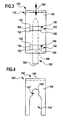
- a second embodiment of a holding device 100 shown in FIG. 4 differs from the first embodiment described above only in that the contact leg 140 of the first bracket 142 not with a single passage opening 144 with a closed edge, but instead with a large passage opening 144 'and a smaller one Passage opening 144 "is provided, none of these passage openings has a closed edge, but the larger passage opening 144 'at the front edge of the contact leg 140 and the smaller opening 144 "at its front end into the larger one Passage opening 144 'opens.
- the holding device 100 is arranged so that the connecting pipe 126 through the am best fitting passage opening 144 ', 144 ".
Landscapes
- Engineering & Computer Science (AREA)
- Water Supply & Treatment (AREA)
- Health & Medical Sciences (AREA)
- Life Sciences & Earth Sciences (AREA)
- Hydrology & Water Resources (AREA)
- Public Health (AREA)
- Environmental & Geological Engineering (AREA)
- Domestic Plumbing Installations (AREA)
- Workshop Equipment, Work Benches, Supports, Or Storage Means (AREA)
- Jigs For Machine Tools (AREA)
- Manipulator (AREA)
- Supports Or Holders For Household Use (AREA)
- Sink And Installation For Waste Water (AREA)
Abstract
Description
Die Montage einer Armatur, beispielsweise einer Mischbatterie, an einer Spüle kann Probleme aufwerfen, insbesondere dann, wenn die Armatur schwer ist und die Spüle aus einem relativ dünnen Material, beispielsweise aus einem Edelstahlblech, hergestellt ist. In solchen Fällen kann häufig nur eine vergleichsweise labile Fixierung der Armatur an der Spüle erzielt werden.Installation of a tap, for example a mixer tap, on a sink can cause problems, especially when the valve is heavy and the sink made of a relatively thin material, for example one Stainless steel sheet, is made. In such cases, often only one can be comparative unstable fixation of the tap on the sink can be achieved.
Der vorliegenden Erfindung liegt daher die Aufgabe zugrunde, eine Möglichkeit zu schaffen, eine Armatur stabil an einer Spüle zu haltern, die an einer Arbeitsplatte angeordnet ist.The present invention is therefore based on the object of one possibility to create a faucet stable on a sink, on a worktop is arranged.
Diese Aufgabe wird erfindungsgemäß durch eine Haltevorrichtung zum Haltern einer Armatur an einer Spüle, die an einer Arbeitsplatte angeordnet ist, gelöst, wobei die Haltevorrichtung ein erstes Halteelement, das an der Armatur festlegbar ist, und ein zweites Halteelement, das an der Arbeitsplatte festlegbar ist, umfaßt, wobei das erste Halteelement und das zweite Halteelement so miteinander verbindbar sind, daß Kräfte von dem ersten Halteelement auf das zweite Halteelement übertragbar sind.This object is achieved by a holding device for holding a fitting on a sink, which is arranged on a worktop, solved wherein the holding device is a first holding element that can be fixed on the fitting is, and a second holding element that can be fixed to the worktop is included, the first holding element and the second holding element being so are interconnectable that forces from the first holding element to the second holding element are transferable.
Auf diese Weise können auf die Armatur einwirkende Kräfte über die Haltevorrichtung direkt von der Arbeitsplatte aufgenommen werden, ohne daß die an der Arbeitsplatte angeordnete Spüle beansprucht wird. In this way, forces acting on the valve via the holding device can be taken directly from the worktop, without the on the worktop arranged sink is claimed.
Hierdurch ist eine stabile Fixierung der Armatur an der Spüle gewährleistet, welche auch für besonders schwere Armaturen, beispielsweise für mit Schlauchbrausen versehene Mischbatterien, ausreichend ist.This ensures a stable fixation of the tap on the sink, which also for particularly heavy fittings, for example for with Mixer taps provided with showerheads are sufficient.
Besonders günstig ist es, wenn das erste Halteelement und das zweite Halteelement so miteinander verbindbar sind, daß Kräfte in horizontaler Richtung von dem ersten Halteelement auf das zweite Halteelement übertragbar sind.It is particularly favorable if the first holding element and the second holding element are connectable so that forces in the horizontal direction are transferable from the first holding element to the second holding element.
Bei bevorzugten Ausgestaltungen der erfindungsgemäßen Haltevorrichtung ist das erste Halteelement und/oder das zweite Halteelement winkelförmig ausgebildet.In preferred configurations of the holding device according to the invention the first holding element and / or the second holding element is angular.
Das armaturenseitige erste Halteelement weist vorteilhafterweise mindestens eine Durchtrittsöffnung für die Armatur auf.The first holding element on the fitting advantageously has at least one a passage opening for the valve.
Diese Durchtrittsöffnung kann einen offenen Rand oder einen geschlossenen Rand aufweisen.This passage opening can be an open edge or a closed one Have edge.
Eine vielseitige Verwendbarkeit der Haltevorrichtung wird erreicht, wenn das erste Halteelement mindestens zwei Durchtrittsöffnungen für eine Armatur aufweist. In diesem Fall kann die Haltevorrichtung mit Armaturen verwendet werden, die unterschiedlich dicke Anschlußrohre aufweisen, wobei die Haltevorrichtung stets so angeordnet wird, daß das Anschlußrohr der Armatur durch die am besten passende Durchtrittsöffnung hindurchtritt.A versatile usability of the holding device is achieved if that first holding element at least two through openings for a fitting having. In this case, the holding device can be used with fittings are, which have connecting tubes of different thicknesses, the holding device is always arranged so that the connection pipe of the valve through the most suitable passage opening.
Die mindestens zwei Durchtrittsöffnungen des ersten Halteelements können insbesondere von unterschiedlicher Größe sein. The at least two through openings of the first holding element can in particular of different sizes.
Um die Verbindung der Armatur über die Haltevorrichtung mit Arbeitsplatten unterschiedlicher Dicke herstellen zu können, ist es günstig, wenn die Haltevorrichtung eine Führung umfaßt, mittels welcher eines der Halteelemente längs einer Verschiebungsrichtung verschieblich an dem jeweils anderen Halteelement geführt ist.To connect the valve to the worktop using the holding device To be able to produce different thicknesses, it is advantageous if the holding device comprises a guide by means of which one of the holding elements slidable along a displacement direction on the respective other holding element is led.
Eine solche Führung kann insbesondere mindestens eine Führungslasche umfassen, welche das geführte Halteelement umgreift.Such a guide can in particular comprise at least one guide tab, which engages around the guided holding element.
Eine besonders wirksame Übertragung von Kräften und Drehmomenten zwischen den beiden Halteelementen ist gewährleistet, wenn die Führung mindestens zwei längs der Verschiebungsrichtung voneinander beabstandete Führungslaschen umfaßt, welche das geführte Halteelement umgreifen.A particularly effective transmission of forces and torques between the two holding elements is guaranteed if the guide is at least two guide lugs spaced apart along the direction of displacement comprises which encompass the guided holding element.
Da die Arbeitsplatte im montierten Zustand üblicherweise horizontal ausgerichtet ist, ist es günstig, wenn die Verschiebungsrichtung der Führung im montierten Zustand der Haltevorrichtung im wesentlichen vertikal gerichtet ist.As the worktop is usually horizontally aligned when assembled is, it is advantageous if the direction of displacement of the guide in assembled state of the holding device is directed substantially vertically.
Das geführte Halteelement kann dabei das armaturenseitige erste Halteelement oder das arbeitsplattenseitige zweite Halteelement sein.The guided holding element can be the valve-side first holding element or the worktop-side second holding element.
Um eine wirksame Übertragung von Kräften und Drehmomenten von der Haltevorrichtung auf die Arbeitsplatte zu ermöglichen, ist vorteilhafterweise vorgesehen, daß das zweite Halteelement eine Anlagefläche umfaßt, mit welcher das zweite Halteelement im montierten Zustand der Haltevorrichtung an der Arbeitsplatte anliegt. To effectively transmit forces and torques from the holder to allow on the worktop is advantageously provided that the second holding element comprises a contact surface with which the second holding element in the assembled state of the holding device on the Worktop is applied.
Für die Festlegung des zweiten Halteelements an der Arbeitsplatte gibt es verschiedene Möglichkeiten.There are various ways of fixing the second holding element to the worktop Possibilities.
So kann beispielsweise vorgesehen sein, daß die Haltevorrichtung mindestens ein Befestigungsmittel zum Festlegen des zweiten Halteelements an der Arbeitsplatte umfaßt.For example, it can be provided that the holding device at least a fastener for fixing the second holding element to the worktop includes.
Ein solches Befestigungsmittel kann beispielsweise eine Schraube sein, welche in die Arbeitsplatte eingedreht wird.Such a fastener can be, for example, a screw which is screwed into the worktop.
Alternativ oder ergänzend hierzu kann auch vorgesehen sein, daß die Anlagefläche des zweiten Halteelements mittels eines geeigneten Klebemittels mit einer gegenüberliegenden Anlagefläche der Arbeitsplatte verklebt ist.Alternatively or additionally, it can also be provided that the contact surface of the second holding element by means of a suitable adhesive an opposite contact surface of the worktop is glued.
Die Haltevorrichtung muß nicht notwendigerweise zweiteilig ausgebildet sein; vielmehr kann die erfindungsgemäße Haltevorrichtung außer dem armaturenseitigen ersten Halteelement und dem arbeitsplattenseitigen zweiten Halteelement noch weitere Elemente umfassen.The holding device does not necessarily have to be in two parts; rather, the holding device according to the invention can be in addition to the fitting first holding element and the worktop-side second holding element include other elements.
Insbesondere müssen das armaturenseitige erste Halteelement und das arbeitsplattenseitige zweite Halteelement nicht unmittelbar miteinander in Kontakt stehen; vielmehr ist es denkbar, daß mindestens ein weiteres Halteelement vorgesehen ist, welches die mechanische Verbindung zwischen dem ersten Halteelement und dem zweiten Halteelement zur Übertragung von Kräften von dem ersten Halteelement auf das zweite Halteelement herstellt.In particular, the valve-side first holding element and the worktop-side second holding element is not in direct contact with each other stand; rather, it is conceivable that at least one further holding element is provided, which is the mechanical connection between the first Holding element and the second holding element for transmitting forces from the first holding element to the second holding element.
Anspruch 14 ist auf eine Armatur für eine Spüle, die an einer Arbeitsplatte angeordnet ist, gerichtet, welche eine erfindungsgemäße Haltevorrichtung zum Haltern der Armatur an der Spüle umfaßt. Claim 14 is a tap for a sink on a countertop is arranged, directed, which a holding device according to the invention for Holds the tap on the sink.
Anspruch 15 ist auf eine Spüle zum Anordnen an einer Arbeitsplatte gerichtet, welche eine Armatur mit einer erfindungsgemäßen Haltevorrichtung zum Haltern der Armatur an der Spüle umfaßt.Claim 15 is directed to a sink for placement on a worktop, which a fitting with a holding device according to the invention for holding the tap on the sink.
Weitere Vorteile und Merkmale der Erfindung sind Gegenstand der nachfolgenden Beschreibung und der zeichnerischen Darstellung von Ausführungsbeispielen.Further advantages and features of the invention are the subject of the following Description and the graphic representation of exemplary embodiments.
In den Zeichnungen zeigen:
- Fig. 1
- eine schematische Seitenansicht des unteren Bereichs einer Armatur, die mittels einer Haltevorrichtung an einer Arbeitsplatte gehalten ist;
- Fig. 2
- eine perspektivische Darstellung der Haltevorrichtung aus Fig. 1;
- Fig. 3
- eine schematische Vorderansicht der Haltevorrichtung aus Fig. 2, mit Blickrichtung in Richtung des
Pfeiles 3 in Fig. 2; und - Fig. 4
- eine schematische Draufsicht auf einen horizontalen Halteschenkel eines armaturenseitigen Haltewinkels einer zweiten Ausführungsform der Haltevorrichtung.
- Fig. 1
- a schematic side view of the lower region of a fitting which is held on a worktop by means of a holding device;
- Fig. 2
- a perspective view of the holding device of Fig. 1;
- Fig. 3
- is a schematic front view of the holding device of Figure 2, looking in the direction of
arrow 3 in Fig. 2. and - Fig. 4
- is a schematic plan view of a horizontal holding leg of a bracket on the fitting side of a second embodiment of the holding device.
Gleiche oder funktional äquivalente Elemente sind in allen Figuren mit denselben Bezugszeichen bezeichnet. The same or functionally equivalent elements are the same in all figures Reference numerals.
Eine in den Fig. 1 bis 3 dargestellte, als Ganzes mit 100 bezeichnete Haltevorrichtung
dient zum Haltern einer Armatur 102, die beispielsweise als Mischbatterie
ausgebildet sein kann, an einer Spüle 104, welche in eine Aufnahmeöffnung
108 in einer Arbeitsplatte 106 eingesetzt ist.A holding device shown in FIGS. 1 to 3, designated as a whole by 100
is used to hold a
Die Spüle 104 weist einen rings um die Spüle 104 umlaufenden, erhöhten horizontalen
Spülenrand 110 auf, welcher auf dem Rand der Arbeitsplatte 106 ruht
und über eine äußere Schräge 112 zu einer Oberseite 114 der Arbeitsplatte
106 hin abfällt und über eine innere Schräge 116 zu einer horizontalen Armaturentragefläche
118 der Spüle 104 hin abfällt.The
Die Armaturentragefläche 118 fällt über eine dem Spülenrand 110 abgewandte
Schräge 120 zu einer horizontalen Spülenfläche 122 hin ab, in welcher das
oder die Becken der Spüle 104 angeordnet sind.The
Die Armaturentragefläche 118 ist mit einer Durchgangsöffnung 124 für den
Durchtritt eines Anschlußrohrs 126 der Armatur 102 versehen, welche ferner
einen Armaturenkörper 128 umfaßt, dessen Unterseite 130 im montierten Zustand
der Armatur 102 an der Oberseite 132 der Armaturentragefläche 118
anliegt.The
Das Anschlußrohr 126 ist mit einem Außengewinde 134 versehen, auf welches
eine Fixiermutter 136 aufgeschraubt ist.The connecting
Zwischen der Oberseite der Fixiermutter 136 und der Unterseite 138 der Armaturentragefläche
118 ist im montierten Zustand der Haltevorrichtung 100
ein horizontaler Anlageschenkel 140 eines ersten Haltewinkels 142 eingeklemmt,
welcher mit seiner Oberseite flächig an der Unterseite 138 der
Armaturentragefläche 118 und mit seiner Unterseite flächig an der Oberseite
der Fixiermutter 136 anliegt.Between the top of the
Wie am besten aus Fig. 2 zu ersehen ist, ist der Anlageschenkel 140 des ersten
Haltewinkels 142 mit einer Durchtrittsöffnung 144 für das Anschlußrohr
126 der Armatur 102 versehen, welche einen geschlossenen Rand 146 aufweist.As can best be seen from FIG. 2, the
Der erste Haltewinkel 142 umfaßt ferner einen vertikalen Führungsschenkel
148, welcher mit zwei in vertikaler Richtung voneinander beabstandeten Führungslaschen
150 versehen ist.The
Diese Führungslaschen 150 sind dadurch gebildet, daß jeweils zwei horizontale
Schnitte in dem Führungsschenkel 148 erzeugt werden und der Steg 154 zwischen
jeweils zwei Schnitten zu der dem Anlageschenkel 140 abgewandten
Seite des Führungsschenkels 148 hin aus der Ebene des Führungsschenkels
148 herausgebogen wird, so daß in dem Führungsschenkel 148 jeweils eine
Durchgangsöffnung 156 entsteht.These
Im montierten Zustand der Haltevorrichtung 100 erstreckt sich ein vertikaler
Führungsschenkel 158 eines zweiten Haltewinkels 160 zwischen den Führungslaschen
150 und der jeweils zugeordneten Durchgangsöffnung 156 hindurch,
so daß die Führungslaschen 150 zusammen eine Führung 162 bilden,
mittels welcher der Führungsschenkel 158 des zweiten Haltewinkels 160 längs
einer vertikalen Verschiebungsrichtung 164 verschieblich an dem Führungsschenkel
148 des ersten Haltewinkels 142 geführt ist.In the assembled state of the
Dabei liegt die dem ersten Haltewinkel 142 zugewandte Vorderseite des Führungsschenkels
158 flächig an der Rückseite des Führungsschenkels 148 des
ersten Haltewinkels 142 an, während die dem ersten Haltewinkel 142 abgewandte
Rückseite des Führungsschenkels 158 im wesentlichen spielfrei an den
Führungslaschen 150 anliegt.In this case, the front side of the guide leg facing the
Der Führungsschenkel 158 des zweiten Haltewinkels 160 verjüngt sich zu seinem
oberen Ende hin, um das Einführen des Führungsschenkels 158 in die
Führungslaschen 150 des ersten Haltewinkels 152 zu erleichtern.The
Der zweite Haltewinkel 160 umfaßt ferner einen im montierten Zustand der
Haltevorrichtung 100 horizontal ausgerichteten Anlageschenkel 166, dessen
Oberseite 168 flächig an der Unterseite 170 der Arbeitsplatte 106 anliegt.The
Der Anlageschenkel 166 des zweiten Haltewinkels 160 ist mit einem oder
mehreren Durchgangslöchern 172 für den Durchtritt jeweils eines Befestigungsmittels
174, beispielsweise einer Holzschraube, durch den Anlageschenkel
166 versehen.The
Alternativ oder ergänzend zu einer Festlegung des Anlageschenkels 166 des
zweiten Haltewinkels 160 an der Arbeitsplatte 106 mittels des Befestigungsmittels
174 kann vorgesehen sein, daß die Oberseite 168 des Anlageschenkels
166 mittels eines geeigneten Klebemittels mit der Unterseite 170 der Arbeitsplatte
106 verklebt ist.Alternatively or in addition to a determination of the
Um zu verhindern, daß Wasser von der Oberseite 114 der Arbeitsplatte 106 in
den Bereich unterhalb der Spüle 104 gelangen kann, ist zwischen der Oberseite
114 der Arbeitsplatte 106 und der Unterseite des Spülenrands 110 eine
Dichtung 176 aus einer elastischen Kunststoff-Dichtungsmasse, beispielsweise
aus Silikon, vorgesehen. To prevent water from the
Bei der Montage der Armatur 102 an der Spüle 104 und der Spüle 104 an der
Arbeitsplatte 106 wird wie folgt vorgegangen:When fitting the
Zunächst wird das Anschlußrohr 126 der Armatur 102 von oben durch die
Durchgangsöffnung 124 in der Armaturentragefläche 118 der Spüle 104 hindurchgeführt,
bis der Armaturenkörper 128 von oben an der Armaturentragefläche
118 anliegt.First, the connecting
Anschließend wird der erste Haltewinkel 142 der Haltevorrichtung 100 so auf
das Anschlußrohr 126 aufgesteckt, daß das Anschlußrohr 126 durch die
Durchtrittsöffnung 144 in dem Anlageschenkel 140 hindurchtritt.The
In dieser Lage wird der erste Haltewinkel 142 durch Anziehen der Fixiermutter
136 festgelegt.In this position, the
Anschließend wird die Spüle 104 in die Aufnahmeöffnung 108 der Arbeitsplatte
106 eingesetzt und an der Arbeitsplatte 106 festgelegt.Then the
Darauf wird der zweite Haltewinkel 160 mit dem Führungsschenkel 158 voran
von unten in die Führungslaschen 150 des Führungsschenkels 148 des ersten
Haltewinkels 142 eingeschoben, bis die Oberseite 168 des Anlageschenkels
166 des zweiten Haltewinkels 160 an der Unterseite 170 der Arbeitsplatte 106
anliegt.The
Durch die Verschiebbarkeit des zweiten Haltewinkels 160 relativ zu dem ersten
Haltewinkel 142 ist somit gewährleistet, daß der Anlageschenkel 166 des
zweiten Haltewinkels 160 unabhängig von der Dicke der Arbeitsplatte 106
stets zur Anlage an der Unterseite 170 der Arbeitsplatte 106 gebracht werden
kann.Due to the displaceability of the
Schließlich wird der Anlageschenkel 166 des zweiten Haltewinkels 160 durch
Kleben und/oder Verschrauben an der Arbeitsplatte 106 festgelegt, womit die
Montage der Haltevorrichtung 100 abgeschlossen ist.Finally, the
Bei der vorstehend beschriebenen Montage der Haltevorrichtung 100 werden
keinerlei Zug- oder Druckkräfte in vertikaler Richtung auf die Spüle 104 oder
auf die Armatur 102 ausgeübt.In the assembly of the holding
Im Betrieb der Armatur 102 an der Spüle 104 werden durch die Haltevorrichtung
100 sämtliche horizontal gerichteten Kräfte sowie alle auftretenden Drehmomente
vollständig und zuverlässig durch die Haltevorrichtung 100 von der
Armatur 102 auf die Arbeitsplatte 106 übertragen.In operation of the fitting 102 on the
Auf diese Weise ist eine stabile Fixierung der Armatur 102 gewährleistet, welche
auch für besonders schwere Armaturen 102, beispielsweise für mit
Schlauchbrausen versehene Mischbatterien, ausreichend ist.In this way, a stable fixation of the fitting 102 is ensured, which
also for particularly
Eine in Fig. 4 dargestellte zweite Ausführungsform einer Haltevorrichtung 100
unterscheidet sich von der vorstehend beschriebenen ersten Ausführungsform
lediglich dadurch, daß der Anlageschenkel 140 des ersten Haltewinkels 142
nicht mit einer einzelnen Durchtrittsöffnung 144 mit geschlossenem Rand,
sondern statt dessen mit einer großen Durchtrittsöffnung 144' und einer kleineren
Durchtrittsöffnung 144" versehen ist, wobei keine dieser Durchtrittsöffnungen
einen geschlossenen Rand aufweist, sondern die größere Durchtrittsöffnung
144' am vorderen Rand des Anlageschenkels 140 mündet und die
kleinere Durchtrittsöffnung 144" an ihrem vorderen Ende in die größere
Durchtrittsöffnung 144' mündet.A second embodiment of a
Durch das Vorhandensein von zwei Durchtrittsöffnungen 144', 144" in dem
Anlageschenkel 140 des ersten Haltewinkels 142 ist gewährleistet, daß die
Haltevorrichtung 100 zum Haltern von Armaturen 102 mit unterschiedlich
dicken Anschlußrohren 126 verwendet werden kann, wobei die Haltevorrichtung
100 jeweils so angeordnet wird, daß das Anschlußrohr 126 durch die am
besten passende Durchtrittsöffnung 144', 144" hindurchtritt.Due to the presence of two through
Im übrigen stimmt die zweite Ausführungsform einer Haltevorrichtung 100
hinsichtlich Aufbau und Funktion mit der ersten Ausführungsform überein, auf
deren vorstehende Beschreibung insoweit Bezug genommen wird.Otherwise, the second embodiment of a
Claims (15)
Applications Claiming Priority (2)
| Application Number | Priority Date | Filing Date | Title |
|---|---|---|---|
| DE10251568A DE10251568A1 (en) | 2002-11-06 | 2002-11-06 | Holding device for holding a fitting on a sink, which is arranged on a worktop |
| DE10251568 | 2002-11-06 |
Publications (3)
| Publication Number | Publication Date |
|---|---|
| EP1418281A2 true EP1418281A2 (en) | 2004-05-12 |
| EP1418281A3 EP1418281A3 (en) | 2004-12-01 |
| EP1418281B1 EP1418281B1 (en) | 2008-12-24 |
Family
ID=32103361
Family Applications (1)
| Application Number | Title | Priority Date | Filing Date |
|---|---|---|---|
| EP03025062A Expired - Lifetime EP1418281B1 (en) | 2002-11-06 | 2003-10-31 | Support device for supporting an armature on a sink mounted in a countertop |
Country Status (5)
| Country | Link |
|---|---|
| EP (1) | EP1418281B1 (en) |
| AT (1) | ATE418650T1 (en) |
| DE (2) | DE10251568A1 (en) |
| DK (1) | DK1418281T3 (en) |
| ES (1) | ES2316687T3 (en) |
Cited By (2)
| Publication number | Priority date | Publication date | Assignee | Title |
|---|---|---|---|---|
| EP2080838A3 (en) * | 2008-01-18 | 2015-01-21 | Franke Technology and Trademark Ltd | Fixing device to fix a faucet to a furniture-mounted sink |
| WO2020007633A1 (en) * | 2018-07-05 | 2020-01-09 | Franke Technology And Trademark Ltd | Fitting reinforcement for a sink, and method for supporting a fitting on a sink |
Families Citing this family (1)
| Publication number | Priority date | Publication date | Assignee | Title |
|---|---|---|---|---|
| DE102021207776A1 (en) | 2021-07-21 | 2023-01-26 | BSH Hausgeräte GmbH | Arrangement with a sink and a faucet and with a specific bracing device and method |
Citations (1)
| Publication number | Priority date | Publication date | Assignee | Title |
|---|---|---|---|---|
| GB2355284A (en) * | 1999-10-13 | 2001-04-18 | Springfast Ltd | Sink unit fasteners |
Family Cites Families (6)
| Publication number | Priority date | Publication date | Assignee | Title |
|---|---|---|---|---|
| DE8810505U1 (en) * | 1988-08-19 | 1989-02-23 | BTS-Bau-Installations-Systeme GmbH, 8755 Alzenau | Device for holding connection boxes for cold and hot water fittings |
| US5135022A (en) * | 1991-01-17 | 1992-08-04 | Masco Corporation Of Indiana | Vertically adjustable valve fitting assembly for tubs |
| US5143121A (en) * | 1991-11-08 | 1992-09-01 | Kohler Co. | Fluid pulse generating apparatus |
| DE4431869A1 (en) * | 1994-09-07 | 1996-03-14 | Knebel & Roettger Fa | Tap fastener for sinks, worktops, etc. |
| DE4443668C2 (en) * | 1994-12-08 | 2000-03-30 | Grohe Armaturen Friedrich | Outlet fitting with fastening device |
| DE19860186A1 (en) * | 1998-06-29 | 1999-12-30 | Aquis Gmbh Rebstein | Rinsing device has rinsing basin |
-
2002
- 2002-11-06 DE DE10251568A patent/DE10251568A1/en not_active Withdrawn
-
2003
- 2003-10-31 EP EP03025062A patent/EP1418281B1/en not_active Expired - Lifetime
- 2003-10-31 AT AT03025062T patent/ATE418650T1/en active
- 2003-10-31 ES ES03025062T patent/ES2316687T3/en not_active Expired - Lifetime
- 2003-10-31 DK DK03025062T patent/DK1418281T3/en active
- 2003-10-31 DE DE50310968T patent/DE50310968D1/en not_active Expired - Lifetime
Patent Citations (1)
| Publication number | Priority date | Publication date | Assignee | Title |
|---|---|---|---|---|
| GB2355284A (en) * | 1999-10-13 | 2001-04-18 | Springfast Ltd | Sink unit fasteners |
Cited By (2)
| Publication number | Priority date | Publication date | Assignee | Title |
|---|---|---|---|---|
| EP2080838A3 (en) * | 2008-01-18 | 2015-01-21 | Franke Technology and Trademark Ltd | Fixing device to fix a faucet to a furniture-mounted sink |
| WO2020007633A1 (en) * | 2018-07-05 | 2020-01-09 | Franke Technology And Trademark Ltd | Fitting reinforcement for a sink, and method for supporting a fitting on a sink |
Also Published As
| Publication number | Publication date |
|---|---|
| ES2316687T3 (en) | 2009-04-16 |
| EP1418281A3 (en) | 2004-12-01 |
| ATE418650T1 (en) | 2009-01-15 |
| DE50310968D1 (en) | 2009-02-05 |
| EP1418281B1 (en) | 2008-12-24 |
| DK1418281T3 (en) | 2009-03-30 |
| DE10251568A1 (en) | 2004-05-27 |
Similar Documents
| Publication | Publication Date | Title |
|---|---|---|
| DE69514385T2 (en) | TOP MOUNTED BATTERY BATTERY | |
| AT13849U1 (en) | Fastening arrangement for a faucet | |
| EP1418282B1 (en) | Support device for supporting an armature on a sink mounted in a countertop | |
| EP1699981B1 (en) | Plumbing fixture with a single-hole mounting | |
| EP1418281B1 (en) | Support device for supporting an armature on a sink mounted in a countertop | |
| EP0824170B1 (en) | Mounting device for a fitting used for connecting sanitary elements to a wall | |
| DE102005046861B4 (en) | Fixing device for fittings of kitchen sinks | |
| WO2014037413A1 (en) | Drain assembly and method for arranging a drain assembly on a drain connection of a sink | |
| DE202021104030U1 (en) | Fixing device for taps | |
| DE102004036634B4 (en) | Device for gassing liquids and method for mounting the device | |
| DE3613479A1 (en) | Connection elbow for flexible heating pipes | |
| DE10009137C1 (en) | Heating radiator connection for the inflow/return flow pipes has a common cap unit and mountings on the side away from the wall for easy access and simplified fitting to the pipe ends | |
| AT408107B (en) | DEVICE FOR FASTENING A COLD AND A HOT WATER CONNECTION TO A BLINDING PANEL | |
| DE102005037200A1 (en) | Pipe clamp is fastened together at one end by bolt passing through slot in upper flange fitted with flexible lugs which grip bolt thread, head end of shaft fitting into V-shaped slot in lower flange | |
| DE10261798A1 (en) | plumbing fixture | |
| DE3741289A1 (en) | Plumbing block | |
| DE102008062231B4 (en) | Fastening arrangement for attaching a sanitary fitting and adapter | |
| DE10016504A1 (en) | Mounting for a fitting at an underlay has threadings to lock into the underlay with a base to shroud the underlay opening and a lower threaded section to lock the base in place with a soft seal | |
| EP2080838A2 (en) | Fixing device to fix a faucet to a furniture-mounted sink | |
| DE102004058938B4 (en) | U-shaped clamping piece | |
| DE9403872U1 (en) | Pipe clamp | |
| DE3018016A1 (en) | External wall facing panel fixture clasp - is inverted U=shaped with hole in curved shank and opening in other | |
| DE19650971A1 (en) | Tubular levelling piece for connectors plastered into walls | |
| AT409645B (en) | Device for fastening a drainpipe to a mounting rail | |
| DE10012504A1 (en) | Mixer tap fitment and securement centers round combiner complete with finger and spring ring all passed and located both sides of fitment support washer. |
Legal Events
| Date | Code | Title | Description |
|---|---|---|---|
| PUAI | Public reference made under article 153(3) epc to a published international application that has entered the european phase |
Free format text: ORIGINAL CODE: 0009012 |
|
| AK | Designated contracting states |
Kind code of ref document: A2 Designated state(s): AT BE BG CH CY CZ DE DK EE ES FI FR GB GR HU IE IT LI LU MC NL PT RO SE SI SK TR |
|
| AX | Request for extension of the european patent |
Extension state: AL LT LV MK |
|
| PUAL | Search report despatched |
Free format text: ORIGINAL CODE: 0009013 |
|
| AK | Designated contracting states |
Kind code of ref document: A3 Designated state(s): AT BE BG CH CY CZ DE DK EE ES FI FR GB GR HU IE IT LI LU MC NL PT RO SE SI SK TR |
|
| AX | Request for extension of the european patent |
Extension state: AL LT LV MK |
|
| 17P | Request for examination filed |
Effective date: 20050409 |
|
| AKX | Designation fees paid |
Designated state(s): AT BE BG CH CY CZ DE DK EE ES FI FR GB GR HU IE IT LI LU MC NL PT RO SE SI SK TR |
|
| 17Q | First examination report despatched |
Effective date: 20060515 |
|
| GRAP | Despatch of communication of intention to grant a patent |
Free format text: ORIGINAL CODE: EPIDOSNIGR1 |
|
| GRAS | Grant fee paid |
Free format text: ORIGINAL CODE: EPIDOSNIGR3 |
|
| GRAA | (expected) grant |
Free format text: ORIGINAL CODE: 0009210 |
|
| AK | Designated contracting states |
Kind code of ref document: B1 Designated state(s): AT BE BG CH CY CZ DE DK EE ES FI FR GB GR HU IE IT LI LU MC NL PT RO SE SI SK TR |
|
| REG | Reference to a national code |
Ref country code: GB Ref legal event code: FG4D Free format text: NOT ENGLISH |
|
| REG | Reference to a national code |
Ref country code: CH Ref legal event code: NV Representative=s name: ISLER & PEDRAZZINI AG Ref country code: CH Ref legal event code: EP |
|
| REG | Reference to a national code |
Ref country code: IE Ref legal event code: FG4D Free format text: LANGUAGE OF EP DOCUMENT: GERMAN |
|
| REF | Corresponds to: |
Ref document number: 50310968 Country of ref document: DE Date of ref document: 20090205 Kind code of ref document: P |
|
| REG | Reference to a national code |
Ref country code: DK Ref legal event code: T3 |
|
| REG | Reference to a national code |
Ref country code: ES Ref legal event code: FG2A Ref document number: 2316687 Country of ref document: ES Kind code of ref document: T3 |
|
| PG25 | Lapsed in a contracting state [announced via postgrant information from national office to epo] |
Ref country code: NL Free format text: LAPSE BECAUSE OF FAILURE TO SUBMIT A TRANSLATION OF THE DESCRIPTION OR TO PAY THE FEE WITHIN THE PRESCRIBED TIME-LIMIT Effective date: 20081224 Ref country code: FI Free format text: LAPSE BECAUSE OF FAILURE TO SUBMIT A TRANSLATION OF THE DESCRIPTION OR TO PAY THE FEE WITHIN THE PRESCRIBED TIME-LIMIT Effective date: 20081224 Ref country code: SI Free format text: LAPSE BECAUSE OF FAILURE TO SUBMIT A TRANSLATION OF THE DESCRIPTION OR TO PAY THE FEE WITHIN THE PRESCRIBED TIME-LIMIT Effective date: 20081224 |
|
| NLV1 | Nl: lapsed or annulled due to failure to fulfill the requirements of art. 29p and 29m of the patents act | ||
| REG | Reference to a national code |
Ref country code: IE Ref legal event code: FD4D |
|
| PG25 | Lapsed in a contracting state [announced via postgrant information from national office to epo] |
Ref country code: RO Free format text: LAPSE BECAUSE OF FAILURE TO SUBMIT A TRANSLATION OF THE DESCRIPTION OR TO PAY THE FEE WITHIN THE PRESCRIBED TIME-LIMIT Effective date: 20081224 Ref country code: EE Free format text: LAPSE BECAUSE OF FAILURE TO SUBMIT A TRANSLATION OF THE DESCRIPTION OR TO PAY THE FEE WITHIN THE PRESCRIBED TIME-LIMIT Effective date: 20081224 Ref country code: BG Free format text: LAPSE BECAUSE OF FAILURE TO SUBMIT A TRANSLATION OF THE DESCRIPTION OR TO PAY THE FEE WITHIN THE PRESCRIBED TIME-LIMIT Effective date: 20090324 Ref country code: IE Free format text: LAPSE BECAUSE OF FAILURE TO SUBMIT A TRANSLATION OF THE DESCRIPTION OR TO PAY THE FEE WITHIN THE PRESCRIBED TIME-LIMIT Effective date: 20081224 |
|
| PG25 | Lapsed in a contracting state [announced via postgrant information from national office to epo] |
Ref country code: PT Free format text: LAPSE BECAUSE OF FAILURE TO SUBMIT A TRANSLATION OF THE DESCRIPTION OR TO PAY THE FEE WITHIN THE PRESCRIBED TIME-LIMIT Effective date: 20090525 Ref country code: SE Free format text: LAPSE BECAUSE OF FAILURE TO SUBMIT A TRANSLATION OF THE DESCRIPTION OR TO PAY THE FEE WITHIN THE PRESCRIBED TIME-LIMIT Effective date: 20090324 |
|
| PG25 | Lapsed in a contracting state [announced via postgrant information from national office to epo] |
Ref country code: SK Free format text: LAPSE BECAUSE OF FAILURE TO SUBMIT A TRANSLATION OF THE DESCRIPTION OR TO PAY THE FEE WITHIN THE PRESCRIBED TIME-LIMIT Effective date: 20081224 |
|
| PLBE | No opposition filed within time limit |
Free format text: ORIGINAL CODE: 0009261 |
|
| STAA | Information on the status of an ep patent application or granted ep patent |
Free format text: STATUS: NO OPPOSITION FILED WITHIN TIME LIMIT |
|
| 26N | No opposition filed |
Effective date: 20090925 |
|
| PG25 | Lapsed in a contracting state [announced via postgrant information from national office to epo] |
Ref country code: MC Free format text: LAPSE BECAUSE OF NON-PAYMENT OF DUE FEES Effective date: 20091031 |
|
| PG25 | Lapsed in a contracting state [announced via postgrant information from national office to epo] |
Ref country code: GR Free format text: LAPSE BECAUSE OF FAILURE TO SUBMIT A TRANSLATION OF THE DESCRIPTION OR TO PAY THE FEE WITHIN THE PRESCRIBED TIME-LIMIT Effective date: 20090325 |
|
| PGFP | Annual fee paid to national office [announced via postgrant information from national office to epo] |
Ref country code: AT Payment date: 20101014 Year of fee payment: 8 |
|
| PGFP | Annual fee paid to national office [announced via postgrant information from national office to epo] |
Ref country code: DE Payment date: 20101127 Year of fee payment: 8 |
|
| PGFP | Annual fee paid to national office [announced via postgrant information from national office to epo] |
Ref country code: IT Payment date: 20101022 Year of fee payment: 8 Ref country code: GB Payment date: 20101027 Year of fee payment: 8 |
|
| PG25 | Lapsed in a contracting state [announced via postgrant information from national office to epo] |
Ref country code: LU Free format text: LAPSE BECAUSE OF NON-PAYMENT OF DUE FEES Effective date: 20091031 |
|
| PG25 | Lapsed in a contracting state [announced via postgrant information from national office to epo] |
Ref country code: HU Free format text: LAPSE BECAUSE OF FAILURE TO SUBMIT A TRANSLATION OF THE DESCRIPTION OR TO PAY THE FEE WITHIN THE PRESCRIBED TIME-LIMIT Effective date: 20090625 |
|
| PG25 | Lapsed in a contracting state [announced via postgrant information from national office to epo] |
Ref country code: TR Free format text: LAPSE BECAUSE OF FAILURE TO SUBMIT A TRANSLATION OF THE DESCRIPTION OR TO PAY THE FEE WITHIN THE PRESCRIBED TIME-LIMIT Effective date: 20081224 |
|
| PG25 | Lapsed in a contracting state [announced via postgrant information from national office to epo] |
Ref country code: CY Free format text: LAPSE BECAUSE OF FAILURE TO SUBMIT A TRANSLATION OF THE DESCRIPTION OR TO PAY THE FEE WITHIN THE PRESCRIBED TIME-LIMIT Effective date: 20081224 |
|
| PGFP | Annual fee paid to national office [announced via postgrant information from national office to epo] |
Ref country code: CZ Payment date: 20110929 Year of fee payment: 9 |
|
| PGFP | Annual fee paid to national office [announced via postgrant information from national office to epo] |
Ref country code: CH Payment date: 20111012 Year of fee payment: 9 Ref country code: BE Payment date: 20111012 Year of fee payment: 9 Ref country code: DK Payment date: 20111011 Year of fee payment: 9 Ref country code: FR Payment date: 20111103 Year of fee payment: 9 Ref country code: ES Payment date: 20111115 Year of fee payment: 9 |
|
| BERE | Be: lapsed |
Owner name: BLANCO G.M.B.H. + CO KG Effective date: 20121031 |
|
| REG | Reference to a national code |
Ref country code: CH Ref legal event code: PL |
|
| REG | Reference to a national code |
Ref country code: DK Ref legal event code: EBP |
|
| REG | Reference to a national code |
Ref country code: AT Ref legal event code: MM01 Ref document number: 418650 Country of ref document: AT Kind code of ref document: T Effective date: 20121031 |
|
| GBPC | Gb: european patent ceased through non-payment of renewal fee |
Effective date: 20121031 |
|
| REG | Reference to a national code |
Ref country code: FR Ref legal event code: ST Effective date: 20130628 |
|
| PG25 | Lapsed in a contracting state [announced via postgrant information from national office to epo] |
Ref country code: BE Free format text: LAPSE BECAUSE OF NON-PAYMENT OF DUE FEES Effective date: 20121031 Ref country code: CH Free format text: LAPSE BECAUSE OF NON-PAYMENT OF DUE FEES Effective date: 20121031 Ref country code: LI Free format text: LAPSE BECAUSE OF NON-PAYMENT OF DUE FEES Effective date: 20121031 Ref country code: GB Free format text: LAPSE BECAUSE OF NON-PAYMENT OF DUE FEES Effective date: 20121031 Ref country code: AT Free format text: LAPSE BECAUSE OF NON-PAYMENT OF DUE FEES Effective date: 20121031 Ref country code: DE Free format text: LAPSE BECAUSE OF NON-PAYMENT OF DUE FEES Effective date: 20130501 Ref country code: CZ Free format text: LAPSE BECAUSE OF NON-PAYMENT OF DUE FEES Effective date: 20121031 |
|
| REG | Reference to a national code |
Ref country code: DE Ref legal event code: R119 Ref document number: 50310968 Country of ref document: DE Effective date: 20130501 |
|
| PG25 | Lapsed in a contracting state [announced via postgrant information from national office to epo] |
Ref country code: FR Free format text: LAPSE BECAUSE OF NON-PAYMENT OF DUE FEES Effective date: 20121031 Ref country code: IT Free format text: LAPSE BECAUSE OF NON-PAYMENT OF DUE FEES Effective date: 20121031 |
|
| PG25 | Lapsed in a contracting state [announced via postgrant information from national office to epo] |
Ref country code: DK Free format text: LAPSE BECAUSE OF NON-PAYMENT OF DUE FEES Effective date: 20121031 |
|
| REG | Reference to a national code |
Ref country code: ES Ref legal event code: FD2A Effective date: 20140207 |
|
| PG25 | Lapsed in a contracting state [announced via postgrant information from national office to epo] |
Ref country code: ES Free format text: LAPSE BECAUSE OF NON-PAYMENT OF DUE FEES Effective date: 20121101 |