EP1415887A2 - Aktives Lenksystem für ein Mehrspur-Fahrzeug - Google Patents
Aktives Lenksystem für ein Mehrspur-Fahrzeug Download PDFInfo
- Publication number
- EP1415887A2 EP1415887A2 EP03019904A EP03019904A EP1415887A2 EP 1415887 A2 EP1415887 A2 EP 1415887A2 EP 03019904 A EP03019904 A EP 03019904A EP 03019904 A EP03019904 A EP 03019904A EP 1415887 A2 EP1415887 A2 EP 1415887A2
- Authority
- EP
- European Patent Office
- Prior art keywords
- steering
- signal
- servomotor
- angle
- link
- Prior art date
- Legal status (The legal status is an assumption and is not a legal conclusion. Google has not performed a legal analysis and makes no representation as to the accuracy of the status listed.)
- Withdrawn
Links
Images
Classifications
-
- B—PERFORMING OPERATIONS; TRANSPORTING
- B62—LAND VEHICLES FOR TRAVELLING OTHERWISE THAN ON RAILS
- B62D—MOTOR VEHICLES; TRAILERS
- B62D5/00—Power-assisted or power-driven steering
- B62D5/008—Changing the transfer ratio between the steering wheel and the steering gear by variable supply of energy, e.g. by using a superposition gear
Definitions
- the invention relates to an active steering system for a multi-track vehicle, at the one next to one of the vehicle driver with his steering handle a wheel actuator mechanically transmitted steering angle an additional Steering angle initiated by a servomotor and on the steerable vehicle wheels can be implemented, the servomotor from an electronic Control unit taking into account the steering angle request the steering handle signal representing the driver and at least another boundary condition is appropriately controlled and one of the driver's steering handle to the signal path leading to the servomotor is provided.
- the servomotor from an electronic Control unit taking into account the steering angle request the steering handle signal representing the driver and at least another boundary condition is appropriately controlled and one of the driver's steering handle to the signal path leading to the servomotor is provided.
- a conventional steering system for example a passenger car the steerable wheel steering angle implemented via a so-called wheel adjuster Front wheels directly and clearly from the one specified by the driver Steering wheel angle, at least if elastic and stroke effects neglected become.
- a so-called active steering system in particular via a so-called.
- addition gear or superposition gear with the help of a suitable servomotor, in particular electric motor, an additional steering angle overlap.
- a suitable servomotor in particular electric motor
- Pinion angle from the according to the translations in the addition gear weighted sum of steering wheel angle and position angle of the servomotor. This makes it possible, among other things, to determine the vehicle speed and the steering wheel angle dependent and thus variable steering ratio realize. It becomes the wheel steering angle resulting from the driver input if an angle is set, the steering becomes more direct, but becomes an Angle put away or subtracted, so the steering for the sensation the driver more indirect.
- variable steering ratio which is associated with a active steering system according to the preamble of claim 1 achievable is, more precisely the so-called gain of the steering ratio is variable.
- a small steering request specified by the driver can thus be dependent a more or less large one from the current gain Cause adjustment movement on the so-called wheel actuator.
- the solution to this problem is characterized in that in the signal path an electronic loose link or backlash link is provided.
- On such a loose link effectively causes “play” or “lost motion” in the signal path
- the steering handle signal can preferably be via a so-called loose link or filtered backlash element to the electronic control unit become.
- causes such a loose or backlash member that only such signals whose Amplitude starting from an initial position is greater than a predetermined one Threshold is to pass the loose link.
- the present invention is based on the following considerations: Self-excited vibration can only occur in a system and itself maintained when a closed circle occurs between its Elements the vibration propagates. The vibration can thus be thereby preventing between at least two elements of the circle the propagation of the vibration is suppressed. This can include by a bandstop happen that acts in the frequency range of the vibration. The prerequisite for this is that by locking the band area the Useful signals can not be falsified in a relevant manner.
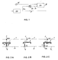
- the amplitude of the vibration is low compared to the amplitude of the Useful sizes, however, the vibration can also be eliminated by that signals are only passed if their amplitude exceed a certain value. This is achieved through a so-called lot, their principle with mechanical implementation in the accompanying figure sequence 2a, 2b, 2c is shown.
- An input signal 1 is from a side Displacement (along a horizontal 3) of a U-shaped bracket 2 represents, while a corresponding output signal 11 by a lateral displacement of one into the U-shaped area of the bracket 2 protruding pin 12 (along a horizontal 13) is shown.
- the bracket 2 is in its central position, in which the pin 12 exactly between the horizontal dimension 2 ⁇ D spaced apart lateral legs of the bracket 2.
- Fig. 2a shows (compared to Fig. 2a) a relatively low input signal 1, i.e. the bracket 2 is slightly deflected laterally without the leg on the pin 12, so that here the output signal 11 compared to the Output signal 11 from Figure 2a is unchanged.
- the input signal 1 has a certain threshold value, namely "D" here starting from the middle position, in which one leg of the Bracket 2 comes to rest on pin 12, so when it increases Input signal 1 taken this pin 12 and a correspondingly large Output signal 11 generated.
- the invention proposes to provide an electronic loose link or backlash link, specifically on a suitable one Place in the signal path between the driver's steering handle and the servomotor that sets a steering angle on the steerable vehicle wheels.
- this said loose link can be provided in the electronic control unit already mentioned, which is a component of this signal path, but the backlash or loose link can also be located downstream of this control unit, for example.
- the driver's steering signal is filtered through an electronic loose element and passed on to the electronic control unit which controls the servomotor.
- reference numeral 20 denoting the steering handle of the vehicle driver, of which a value for the steering angle request 21, on the one hand, mechanically to a wheel actuator (not shown) for implementing a steering angle on the steerable vehicle wheels is directed and on the other hand this "desired steering angle" 21 is guided via a branching path 21a through a loose link 22, from where this predetermined by the driver and in the loose link 22 revised accordingly 23 leads to an electronic control unit 24.
- This takes into account at least one other boundary condition; here the value for the current driving speed 25 of the vehicle.
- the output variable 26 of the control unit 24 is then used to control a servomotor, not shown, with which a further steering angle can be set on the steerable vehicle wheels in addition to the steering angle request 21, or the steering angle request 21 can be set by means of the servomotor suitable additional steering angle, which can be rectified or counter-directed, are superimposed.
- the loose link 22 is a function that can also be implemented programmatically within the electronic control unit 24 and that only signals above a certain amplitude starting from a so-called initial position, such as this in FIGS. 2a-2c by the distance 2 ⁇ D of the two side legs is shown.
- This starting position is practically the respective current position of the loose link or the current value in the loose link, ie, according to the sequence of figures 2a - 2c, the size of the output signal 11.
- a new input signal 1 is specified in relation to this value that deviates from the current output signal (starting position) by more than the stated amplitude or fluctuation range, this new input signal is taken into account, otherwise this new input signal is not taken into account and therefore goes under as "play” or "lost motion".
- the steering handle signal mentioned is preferably a Steering wheel angle signal, i.e. by the angle of rotation of the driver operated Steering wheel, while said additional steering angle is preferred over a in particular as a planetary gear superposition gear in the vehicle steering system can be initiated.
- the design of the loose link depends solely on the amplitude of the vibration to be suppressed. Because of the non-linear effects caused vibration or its amplitude and frequency approximately is constant, this procedure represents a very robust solution
- the amplitude of the vibration of the steering wheel angle signal is wide below the size of signal changes that may be intended for further changes
- Driving stabilization functions are relevant. Because of this, can the filtered steering wheel angle signal without difficulty as an input signal be used for driving stabilizing functions.
- Through the loose link interference is also filtered from the steering wheel angle signal, which lead to abrupt activation pulses of the servomotor mentioned. Therefore, by using the loose link, the haptics and acoustics of the active steering system improved, although it should also be pointed out that quite a lot of details differ from the above explanations can be designed without leaving the content of the claims.
Landscapes
- Engineering & Computer Science (AREA)
- Chemical & Material Sciences (AREA)
- Combustion & Propulsion (AREA)
- Transportation (AREA)
- Mechanical Engineering (AREA)
- Steering Control In Accordance With Driving Conditions (AREA)
Abstract
Description
Claims (4)
- Aktives Lenksystem für ein Mehrspur-Fahrzeug, bei dem neben einem vom Fzg.-Fahrer mit seiner Lenkhandhabe letztlich auf einen Rad-Steller mechanisch übertragenen Lenkwinkel (21) ein zusätzlicher Lenkwinkel (26) von einem Stellmotor eingeleitet und an den lenkbaren Fzg.-Rädern umgesetzt werden kann, wobei der Stellmotor von einer elektronischen Steuereinheit (24) unter Berücksichtigung eines den Lenkwinkel-Wunsch (21) des Fahrers repräsentierenden Lenkhandhabe-Signals sowie zumindest einer weiteren Randbedingung geeignet angesteuert wird und hierfür ein von der Lenkhandhabe (20) des Fahrers über die elektronische Steuereinheit (24) zum Stellmotor führender Signalpfad vorgesehen ist,
dadurch gekennzeichnet, dass im Signalpfad ein elektronisches Lose-Glied (22) oder backlash-Glied (22) vorgesehen ist. - Aktives Lenksystem nach Anspruch 1,
dadurch gekennzeichnet, dass das Lenkhandhabe-Signal (21 a) über ein sog. Lose-Glied (22) oder backlash-Glied (22) gefiltert an die elektronische Steuereinheit (24) geleitet wird. - Aktives Lenksystem nach Anspruch 1 oder 2,
dadurch gekennzeichnet, dass lediglich solche Signale, deren Amplitude ausgehend von einer Ausgangsstellung größer als ein vorgegebener Schwellwert (D) ist, das Lose-Glied (22) passieren. - Aktives Lenksystem nach einem der vorangegangenen Ansprüche,
dadurch gekennzeichnet, dass das Lenkhandhabe-Signal ein Lenkradwinkel-Signal ist und der zusätzliche Lenkwinkel über ein insbesondere als Planetengetriebe ausgebildetes Überlagerungsgetriebe in das Lenksystem eingeleitet wird.
Applications Claiming Priority (2)
| Application Number | Priority Date | Filing Date | Title |
|---|---|---|---|
| DE10250738 | 2002-10-31 | ||
| DE2002150738 DE10250738A1 (de) | 2002-10-31 | 2002-10-31 | Aktives Lenksystem für ein Mehrspur-Fahrzeug |
Publications (2)
| Publication Number | Publication Date |
|---|---|
| EP1415887A2 true EP1415887A2 (de) | 2004-05-06 |
| EP1415887A3 EP1415887A3 (de) | 2004-10-20 |
Family
ID=32087301
Family Applications (1)
| Application Number | Title | Priority Date | Filing Date |
|---|---|---|---|
| EP03019904A Withdrawn EP1415887A3 (de) | 2002-10-31 | 2003-09-02 | Aktives Lenksystem für ein Mehrspur-Fahrzeug |
Country Status (2)
| Country | Link |
|---|---|
| EP (1) | EP1415887A3 (de) |
| DE (1) | DE10250738A1 (de) |
Family Cites Families (7)
| Publication number | Priority date | Publication date | Assignee | Title |
|---|---|---|---|---|
| IT1250885B (it) * | 1991-12-20 | 1995-04-21 | Fiat Ricerche | Sistema di sterzatura per il controllo istantaneo del rapporto di sterzo. |
| JPH071933A (ja) * | 1993-06-16 | 1995-01-06 | Mitsubishi Motors Corp | アライメント制御装置 |
| DE4419650B4 (de) * | 1994-01-10 | 2005-05-25 | Volkswagen Ag | Verfahren zum Erkennen eines querdynamisch kritischen oder regelungsbedürftigen Fahrzustandes sowie Vorrichtung hierfür |
| IT1278893B1 (it) * | 1995-01-23 | 1997-11-28 | Francesco Miotto | Comando motorizzato della sterzatura di un veicolo |
| US5576959A (en) * | 1995-03-03 | 1996-11-19 | Ford Motor Company | Method for controlling yaw of a wheeled vehicle based on under-steer and over-steer containment routines |
| JP3708989B2 (ja) * | 1995-05-16 | 2005-10-19 | 三菱自動車工業株式会社 | 車両の旋回制御装置 |
| DE10012133A1 (de) * | 2000-03-13 | 2001-09-27 | Bosch Gmbh Robert | Überwachungssystem zur Überwachung einer Stelleinrichtung im Kraftfahrzeug |
-
2002
- 2002-10-31 DE DE2002150738 patent/DE10250738A1/de not_active Withdrawn
-
2003
- 2003-09-02 EP EP03019904A patent/EP1415887A3/de not_active Withdrawn
Also Published As
| Publication number | Publication date |
|---|---|
| EP1415887A3 (de) | 2004-10-20 |
| DE10250738A1 (de) | 2004-05-13 |
Similar Documents
| Publication | Publication Date | Title |
|---|---|---|
| DE60015348T2 (de) | Verfahren und vorrichtung zur regelung einer elektrischen servolenkung mit adaptiv mischendem drehmomentfilter | |
| EP2744692B1 (de) | Elektromechanischer bremskraftverstärker | |
| EP3024684B1 (de) | Haptisches kraftfahrzeug-fahrpedal mit elastisch angekoppeltem aktuator sowie verfahren und regelungseinheit zum regeln desselben | |
| DE10021903A1 (de) | Lenksystem für ein Fahrzeug | |
| DE19833189A1 (de) | Lenksystem für ein Fahrzeug | |
| WO2018224549A1 (de) | Lenksäule für ein kraftfahrzeug | |
| DE102006019790A1 (de) | Verfahren zur Lenkungsregelung | |
| DE102006025380B4 (de) | Fahrzeuglenksystem zum Setzen einer Lenkreaktion ohne Verwendung einer Differenz zwischen Soll- und Istlenkwinkeln | |
| EP1410972A2 (de) | Fahrzeuglenkvorrichtung und Sicherheitssystem | |
| DE102021202482B4 (de) | Regelungseinrichtung und Verfahren zur Lenkwinkelregelung eines Fahrzeugs | |
| DE10103667A1 (de) | Aktuator für eine Steer-by-Wire-Lenkanlage | |
| DE4122629A1 (de) | Verstellbares pedalwerk fuer kraftfahrzeuge | |
| DE69523075T2 (de) | Motorisch angetriebenes system zum lenken eines fahrzeugs | |
| DE4446123A1 (de) | Vorrichtung zur Einwirkung auf die an der Lenkung wirksamen Kräfte | |
| DE102023205816A1 (de) | Doppelmotorantriebsanordnung | |
| DE602005000165T2 (de) | Elektrische Servolenkeinrichtung für ein Kraftfahrzeug, Lenkanordnung mit einer solchen Servolenkeinrichtung und mit einer solchen Lenkanordnung ausgerüstetes Kraftfahrzeug | |
| EP1319872B1 (de) | Schaltvorrichtung für einen Handschalhebel | |
| DE19511273C2 (de) | Lenksystem für Kraftfahrzeuge | |
| EP1415887A2 (de) | Aktives Lenksystem für ein Mehrspur-Fahrzeug | |
| EP1508493A2 (de) | Lenksystem für ein Kraftfahrzeug mit einer Servolenkung | |
| EP1526997B1 (de) | Kraftfahrzeuglenkung mit berlagerungslenkung | |
| EP0936985A1 (de) | Lenkvorrichtung mit betätigungsring | |
| DE102019213959A1 (de) | Drehsteuereinrichtung zum Lenken | |
| DE19952709C2 (de) | Vorrichtung zum Steuern | |
| DE102022203129A1 (de) | Verfahren zur Bestimmung eines geregelten Handmoments und Lenksystem |
Legal Events
| Date | Code | Title | Description |
|---|---|---|---|
| PUAI | Public reference made under article 153(3) epc to a published international application that has entered the european phase |
Free format text: ORIGINAL CODE: 0009012 |
|
| AK | Designated contracting states |
Kind code of ref document: A2 Designated state(s): AT BE BG CH CY CZ DE DK EE ES FI FR GB GR HU IE IT LI LU MC NL PT RO SE SI SK TR |
|
| AX | Request for extension of the european patent |
Extension state: AL LT LV MK |
|
| PUAL | Search report despatched |
Free format text: ORIGINAL CODE: 0009013 |
|
| AK | Designated contracting states |
Kind code of ref document: A3 Designated state(s): AT BE BG CH CY CZ DE DK EE ES FI FR GB GR HU IE IT LI LU MC NL PT RO SE SI SK TR |
|
| AX | Request for extension of the european patent |
Extension state: AL LT LV MK |
|
| STAA | Information on the status of an ep patent application or granted ep patent |
Free format text: STATUS: THE APPLICATION HAS BEEN WITHDRAWN |
|
| 18W | Application withdrawn |
Effective date: 20041217 |