EP1415290B1 - Verbesserte Fernbedienung mit wechselnder Betriebsart - Google Patents
Verbesserte Fernbedienung mit wechselnder Betriebsart Download PDFInfo
- Publication number
- EP1415290B1 EP1415290B1 EP02751486.8A EP02751486A EP1415290B1 EP 1415290 B1 EP1415290 B1 EP 1415290B1 EP 02751486 A EP02751486 A EP 02751486A EP 1415290 B1 EP1415290 B1 EP 1415290B1
- Authority
- EP
- European Patent Office
- Prior art keywords
- remote control
- box
- support
- management system
- home automation
- Prior art date
- Legal status (The legal status is an assumption and is not a legal conclusion. Google has not performed a legal analysis and makes no representation as to the accuracy of the status listed.)
- Expired - Lifetime
Links
- 238000012986 modification Methods 0.000 claims description 4
- 230000004048 modification Effects 0.000 claims description 4
- 230000005355 Hall effect Effects 0.000 claims description 3
- 238000013519 translation Methods 0.000 claims description 3
- 238000009434 installation Methods 0.000 description 4
- 238000006073 displacement reaction Methods 0.000 description 3
- 238000010438 heat treatment Methods 0.000 description 3
- 230000000295 complement effect Effects 0.000 description 2
- 238000013461 design Methods 0.000 description 2
- 238000001514 detection method Methods 0.000 description 2
- 208000010415 Low Vision Diseases 0.000 description 1
- 235000014676 Phragmites communis Nutrition 0.000 description 1
- 238000004378 air conditioning Methods 0.000 description 1
- 238000004891 communication Methods 0.000 description 1
- 238000012790 confirmation Methods 0.000 description 1
- 238000005553 drilling Methods 0.000 description 1
- 238000003780 insertion Methods 0.000 description 1
- 230000037431 insertion Effects 0.000 description 1
- 230000004303 low vision Effects 0.000 description 1
- 238000000034 method Methods 0.000 description 1
- 230000008520 organization Effects 0.000 description 1
- 230000004224 protection Effects 0.000 description 1
- 238000011084 recovery Methods 0.000 description 1
- 238000007789 sealing Methods 0.000 description 1
- 238000000926 separation method Methods 0.000 description 1
- 229940055944 soliris Drugs 0.000 description 1
- 230000002269 spontaneous effect Effects 0.000 description 1
- 238000012360 testing method Methods 0.000 description 1
Images

Classifications
-
- G—PHYSICS
- G08—SIGNALLING
- G08C—TRANSMISSION SYSTEMS FOR MEASURED VALUES, CONTROL OR SIMILAR SIGNALS
- G08C19/00—Electric signal transmission systems
- G08C19/16—Electric signal transmission systems in which transmission is by pulses
- G08C19/28—Electric signal transmission systems in which transmission is by pulses using pulse code
Definitions
- the present invention relates to a remote control device of a home automation type comfort management system, having at least two modes of operation, a first automatic mode of operation, and a second mode of manual operation and comprising a remote control consisting of by a housing comprising at least one remote control transmitter and a control keyboard.
- the controlled system consists, for example, in a control means of a heating and air conditioning device, a device for moving sashes or dynamic solar protections, or lighting.
- the affected systems are found in homes, offices or commercial buildings.
- It relates more particularly to a remote control device in which at least two modes of operation are provided, a so-called manual mode, in which the device essentially obeys orders given by a manual control means, for example a remote control box. , and a so-called automatic mode, in which the device essentially obeys the orders of a supervisor program.
- this mode change is provided by a specific push button.
- a push button is aesthetically more pleasant than a pull switch. Its use facilitates compliance with any sealing constraints. It is very economical. On the other hand, it does not indicate what state we are after the maneuver. It is therefore necessary to add at least one indicating indicator, such as a light emitting diode, to indicate this state.
- the mode indicator light can not be permanently on for simple consumption reasons. It is therefore at the moment when the user will act on one of the control buttons that this mode indicator function will be activated.
- This reproach can also be applied in the same way to older devices containing a pull switch, or even to a device which contains one or more light-emitting diodes permanently illuminated.
- the design of the product most often requires that the pull of the switch is discreet, and moreover it is not written in large characters on the front plate of the remote control product the meaning of each position, or the status of the switch. 'an indicator. It is therefore understandable that elderly or just low vision will have trouble knowing the state of the system, except to move to be closer to the control point.
- the remote control can also give spontaneous orders for the user to find from one room to another the same application. For example, if the user leaves, with his remote control, a first room in which the TV is connected to a program, and it enters a second room containing a TV, the remote control will eventually turn it on and will switch on this same program.
- the location of one room to another can be provided by the detection of transmitters fixed in each room, or by more sophisticated means, GPS type.
- Document is known US 5,790,021 a device for finding a remote control by causing it to be emitted by an audible signal.
- This device comprises the remote control and a support comprising an electronic circuit. When the remote control is removed from this support, the electronic circuit is closed and sends to the remote after a certain time a signal controlling the emission of an audible signal by the remote control and to find it.
- Document is known DE 39 33 966 a keyboard device whose keys are movable between a first configuration and a second configuration. In the first configuration, the presses on the keys have a first meaning and, in the second configuration, the presses on the keys have a second meaning.
- the present invention proposes to overcome the disadvantages of the prior devices, by proposing a control ergonomics mode changes, which is much more intuitive than those of the prior art, and which may, in some embodiments of products according to this ergonomics, contribute to permanent visibility of the mode used, while ensuring autonomy and reduced costs.
- the remote control according to the invention is not intended to cause changes in mode during a passage from one room to another of the user, and is not concerned about the position of said user , but the change of mode is done by moving a part of the device relative to the other, the mode change activated according to the invention must instead be able to be performed in the same room.
- the device of the invention does not use communication with an information source, and does not require any modification of the functionalities of the user interface.
- the remote control device is characterized in that said housing is movably mounted in a support between a first position corresponding to the first operating mode and at least a second position corresponding to the second operating mode. and in that it comprises means for detecting the position of the housing relative to the support and means for modifying the operating mode as a function of the detected position of the housing.
- the housing is mounted movable in translation in the support.
- the means for detecting the position of the housing relative to the support comprise at least one sensor and the means for modifying the operating mode as a function of the detected position of the housing comprise a processor.
- the sensor may consist of a push button or a magnetic switch or a Hall effect switch.
- the housing is elongate, of substantially parallelepipedal shape, while the support is for example an upwardly open frame, having the shape of a U, to comprise a lower border, and two lateral borders, while the main housing is slidably mounted in the central housing between the two side edges to be movable from the first position to at least a second position.
- the housing can be positioned in two positions corresponding to two modes of automatic operation, and in a position corresponding to a manual mode of operation, and vice versa in two modes of manual operation, and in a single position corresponding to a mode of operation. automatic.
- the device advantageously has means for indexing the relative positions of the housing relative to the support.
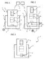
- the figures 5 represents a diagrammatic front view, an alternative embodiment of the remote control.
- the remote control with the general reference (1) consists of two parts (2, 3), movable relative to each other.
- a main housing (2) comprising at least one remote control transmitter (4) and a control keyboard (5).
- the said main housing (2) is movably mounted in translation in a support (3), which can serve as a wall, table or other support.
- the transmitter (4) is for example of the radio frequency type, while the control keyboard (5) makes it possible to send commands to a receiver (11) of the installation, connected to a control device (12). ).
- the housing (2) is elongate, of substantially parallelepipedal shape, while the support (3) is for example an upwardly open frame, having the shape of a U, to comprise a lower border (6), and two borders (7, 8) while the main housing (2) is slidably mounted in the central housing (9) between the two side edges (7, 8) to be movable from a first position (A) as illustrated. to the figure 1 to at least a second position (B) as shown in figure 2 .
- the remote control In the first position (A), the remote control is in its automatic operating position and it is this mode of operation which is activated, in the second position (B), it is the manual mode which is activated.
- the main housing (2) In the first position (A), said automatic operating position, the main housing (2) is in the lower position in the receiving housing (9), that is to say completely engaged in its support (3), of so that the lower edge (10) of said housing is in contact with the lower edge (6) of said support (3).
- the main housing (2) In the second position (B), said manual operating position, the main housing (2) is moved from its first position (A) upwards by a distance (D1) so that its lower edge ( 10) is separated from the lower edge (6) of the support (3), to be no longer in contact with the latter. Note that this separation (D1) is visible unambiguously at a distance of a few meters, and the user can then know if his remote control is in manual operating position, or automatic.
- the change of position is sufficient to move the control device (12) from a first mode to a second mode of operation. It is understood that as soon as the housing (2) has reached its separate position (B) of manual operation, this operating mode no longer changes when increasing the distance (D1). Thus, the user can, in the so-called manual operation, either leave the housing in its support, as illustrated in FIG. figure 2 or remove it completely to separate it from the support.
- the device comprises means for detecting the position of the housing (2), with respect to the support (3).
- the housing (2) comprises in its lower part a sensor (13) connected to the processor (14), said sensor being intended to recognize if the housing is in the first position (A), or in the second position (B) .
- the sensor (13) can be of any type, and for example a switch or a simple push button whose moving part is pressed by the contact with the support (3) when the lower part of the housing (2) is in the position (A) as illustrated in figure 1 .
- the distance (D1) to move from the first position to the second position will be greater than the stroke (D2) of the moving part of the push button.
- This sensor embodiment (13) will be advantageously replaced by a shape, known to those skilled in the art, not requiring drilling the housing.
- a magnetic switch with a flexible blade (Reed) disposed on the same printed circuit as the processor (14) intended to be operated very short distance by a magnet (15) which would be housed in the lower edge (6) of the support (3) facing the location of the sensor (13).
- a Hall effect sensor One could also use a Hall effect sensor.
- the housing includes means for changing the operating mode according to the detected position of the housing.
- the sensor (13) is connected to an input of the processor (14), for example to an interrupt input.
- the sensor and this input are in the logic state 1 in the first position (A) and in the logic state 0 in the second position (B).
- the processor On change of state of such an input, the processor, possibly put in idle mode to reduce its consumption, switches to active mode.
- the figure 4 represents a flowchart of the interrupt program activated at the input (20) by a change of state of the processor.
- the state of the sensor is read by the software module (21), then a test (22) is performed to orient the program on the module (23) if it is a state 1 or on the module (24). ) if it is a state (0).
- the processor transmits to the transmitter (4) a command to switch to automatic mode.
- the processor transmits to the transmitter a command to switch to manual mode. When this command is received by the receiver (11), it causes the change of mode of the control device (12).
- the invention is not limited to the embodiment described above. Indeed, it is possible to imagine, for example, several positions that are well separated visually, for each of the modes of operation. Thus, one could provide two positions corresponding to two modes of automatic operation, and a position corresponding to a manual mode of operation. Similarly, one could provide two positions corresponding to two manual modes of operation, and a single position corresponding to an automatic mode of operation.
- the figure 5 illustrates an alternative embodiment, according to which, there are three positions for the housing, which comprises two sensors (13 ', 13 "), activated or not by the same magnet (15).
- the sensor (13 ') In the fully engaged position, the sensor (13 ') is activated, a height displacement (D3) activates the sensor (13 "), a displacement of height equal to or greater than (D4) no longer activates any sensor.
- means for indexing the relative positions of the housing (2) with respect to the support (3) can advantageously be provided, for example, projecting profiles arranged on the side walls of the housing (2), intended for engage in corresponding hollow profiles made on the support (3), and then define stable and defined positions of the housing in its support.
- the displacement of the housing relative to the support is a translational movement, but it could be otherwise.
- the support comprises several housings (9) for receiving the housing.
- one of the housing could be dedicated to the first position corresponding to automatic operation, while a second housing could be dedicated to the second position corresponding to manual operation.
- the various positions of the housing are well visually identifiable, and translate at best, intuitively the current mode of operation.
Landscapes
- Physics & Mathematics (AREA)
- General Physics & Mathematics (AREA)
- Selective Calling Equipment (AREA)
Claims (10)
- Vorrichtung zur Fernbedienung eines Komfortmanagementsystems des sogenannten domotischen Typs, die mindestens zwei Betriebsarten hat, eine erste automatische Betriebsart, bei der das System den Befehlen eines Supervisor-Programms gehorcht, und eine zweite manuelle Betriebsart, bei der das System den Befehlen gehorcht, die von einem manuellen Steuermittel gegeben werden, umfassend eine Fernsteuerung, die von einem Gehäuse (2) gebildet wird, das mindestens einen Fernsteuerungssender (4) und eine Bedientastatur (5) umfasst, dadurch gekennzeichnet, dass das Gehäuse (2) in einem Halter (3) montiert ist und zwischen einer ersten Position (A), die der ersten Betriebsart entspricht, und mindestens einer zweiten Position (B), die der zweiten Betriebsart entspricht, bewegbar ist, und dass es Detektionsmittel (13) der Position des Gehäuses (2) im Verhältnis zum Halter (3) umfasst und Mittel (14), die die Änderung der Betriebsart in Abhängigkeit von der ermittelten Position des Gehäuses erlauben.
- Vorrichtung zur Fernbedienung eines domotischen Komfortmanagementsystems nach Anspruch 1, dadurch gekennzeichnet, dass das Gehäuse (2) im Halter (3) verlagernd beweglich montiert ist.
- Vorrichtung zur Fernbedienung eines domotischen Komfortmanagementsystems nach einem der Ansprüche 1 oder 2, dadurch gekennzeichnet, dass die Detektionsmittel der Position des Gehäuses (2) im Verhältnis zum Halter (3) mindestens einen Sensor (13) umfassen und dass die Mittel, die die Änderung der Betriebsart in Abhängigkeit von der ermittelten Position des Gehäuses erlauben, einen Prozessor (14) umfassen.
- Vorrichtung zur Fernbedienung eines domotischen Komfortmanagementsystems nach Anspruch 3, dadurch gekennzeichnet, dass der Sensor (13) ein Druckknopf oder ein Magnetschalter oder ein Schalter mit Hall-Effekt ist.
- Vorrichtung zur Fernbedienung eines domotischen Komfortmanagementsystems nach einem der vorangehenden Ansprüche, dadurch gekennzeichnet, dass das Gehäuse (2) länglich, etwa parallelepipedisch ist, wogegen der Halter (3) beispielsweise ein nach oben offener Rahmen in U-Form ist, um einen unteren Rand (6) und zwei Seitenränder (7, 8) zu umfassen, wobei das Hauptgehäuse (2) gleitend in der zentralen Aufnahme (9) zwischen den zwei Seitenrändern (7, 8) montiert ist, um von der ersten Position (A) in mindestens eine zweite Position (B) verschiebbar zu sein.
- Vorrichtung zur Fernbedienung eines domotischen Komfortmanagementsystems nach einem der vorangehenden Ansprüche, dadurch gekennzeichnet, dass das Gehäuse (2) in zwei Positionen positionierbar ist, die zwei automatischen Betriebsarten entsprechen und in eine Position, die einer manuellen Betriebsart entspricht.
- Vorrichtung zur Fernbedienung eines domotischen Komfortmanagementsystems nach einem der Ansprüche 1 bis 5, dadurch gekennzeichnet, dass das Gehäuse (2) in zwei Positionen positionierbar ist, die zwei manuellen Betriebsarten entsprechen und in eine Position, die einer automatischen Betriebsart entspricht.
- Vorrichtung zur Fernbedienung eines domotischen Komfortmanagementsystems nach einem der vorangehenden Ansprüche, dadurch gekennzeichnet, dass sie Indexierungsmittel der relativen Positionen des Gehäuses (2) im Verhältnis zum Halter (3) aufweist.
- Vorrichtung zur Fernbedienung eines domotischen Komfortmanagementsystems nach einem der vorangehenden Ansprüche, dadurch gekennzeichnet, dass die Betriebsergonomie der Fernbedienung durch eine Modusänderung geändert wird.
- Vorrichtung zur Fernbedienung eines domotischen Komfortmanagementsystems nach einem der vorangehenden Ansprüche, dadurch gekennzeichnet, dass die zweite Position (B) eine Position ist, in der die Fernbedienung (2) vom Halter (3) getrennt ist.
Applications Claiming Priority (3)
| Application Number | Priority Date | Filing Date | Title |
|---|---|---|---|
| FR0110486A FR2828319B1 (fr) | 2001-08-06 | 2001-08-06 | Perfectionnement pour telecommande a changement de mode de fonctionnement |
| FR0110486 | 2001-08-06 | ||
| PCT/IB2002/002995 WO2003015049A1 (fr) | 2001-08-06 | 2002-07-31 | Perfectionnement pour telecommande a changement de mode de fonctionnement |
Publications (2)
| Publication Number | Publication Date |
|---|---|
| EP1415290A1 EP1415290A1 (de) | 2004-05-06 |
| EP1415290B1 true EP1415290B1 (de) | 2013-05-29 |
Family
ID=8866305
Family Applications (1)
| Application Number | Title | Priority Date | Filing Date |
|---|---|---|---|
| EP02751486.8A Expired - Lifetime EP1415290B1 (de) | 2001-08-06 | 2002-07-31 | Verbesserte Fernbedienung mit wechselnder Betriebsart |
Country Status (9)
| Country | Link |
|---|---|
| US (1) | US7071836B2 (de) |
| EP (1) | EP1415290B1 (de) |
| JP (1) | JP4173808B2 (de) |
| CN (1) | CN1242368C (de) |
| AU (1) | AU2002355494B2 (de) |
| CA (1) | CA2456215C (de) |
| ES (1) | ES2253137T1 (de) |
| FR (1) | FR2828319B1 (de) |
| WO (1) | WO2003015049A1 (de) |
Families Citing this family (10)
| Publication number | Priority date | Publication date | Assignee | Title |
|---|---|---|---|---|
| KR20040080663A (ko) * | 2003-03-12 | 2004-09-20 | 삼성전자주식회사 | 유비퀴터스 서비스 기능을 가지는 사설 네트워크 시스템및 그의 동작방법 |
| US9277156B2 (en) * | 2005-11-30 | 2016-03-01 | Broadcom Corporation | Universal parallel television remote control |
| US7723939B2 (en) * | 2006-05-23 | 2010-05-25 | Lutron Electronics Co., Inc. | Radio-frequency controlled motorized roller shade |
| FR2910677B1 (fr) | 2006-12-26 | 2009-02-27 | Somfy Sas | Capteur-emetteur de securite pour la detection de vent dans une installation domotique |
| US8854798B1 (en) * | 2009-10-02 | 2014-10-07 | Qmotion Incorporated | Transmitter holder apparatus and method |
| FR2960086B1 (fr) * | 2010-05-12 | 2012-08-03 | Somfy Sas | Procede de localisation d'une unite de commande d'un actionneur de manoeuvre d'un element de couverture de fenetre |
| EP2667362B1 (de) * | 2012-05-23 | 2017-08-30 | Alcatel Lucent | Steuervorrichtung |
| US9384657B2 (en) | 2013-06-13 | 2016-07-05 | The Watt Stopper, Inc. | Architectural covering cradle system, multifunction remote and method of use |
| US11236857B2 (en) | 2019-01-18 | 2022-02-01 | Current Products Corp. | Low profile remote and wall plate apparatus |
| CN115524986B (zh) * | 2021-12-30 | 2024-09-24 | 青岛海尔智能家电科技有限公司 | 基于双模式开关面板的智能家居控制方法、装置及系统 |
Family Cites Families (12)
| Publication number | Priority date | Publication date | Assignee | Title |
|---|---|---|---|---|
| JPS61138046A (ja) * | 1984-12-06 | 1986-06-25 | Mitsubishi Electric Corp | 空気調和機のリモコン装置 |
| JPH0257636U (de) * | 1988-10-20 | 1990-04-25 | ||
| CA2005070C (en) * | 1988-12-23 | 1999-04-27 | Henry C. Yuen | Apparatus and method for using encoded video recorder/player timer preprogramming information |
| JPH06159779A (ja) * | 1992-11-19 | 1994-06-07 | Matsushita Electric Ind Co Ltd | 空気調和機の遠隔操作装置 |
| JP3144940B2 (ja) * | 1993-03-02 | 2001-03-12 | 松下電器産業株式会社 | 空気調和機のリモコン装置 |
| JP3394106B2 (ja) * | 1995-01-13 | 2003-04-07 | 小泉産業株式会社 | リモコン送信器 |
| US5790021A (en) * | 1996-11-27 | 1998-08-04 | Mickel; Ivor | Remote control finder |
| JPH10210565A (ja) * | 1997-01-28 | 1998-08-07 | Matsushita Electric Works Ltd | センサリモコンによる制御装置 |
| US6011489A (en) * | 1998-01-12 | 2000-01-04 | Toymax Inc. | Remotely controlled toy and wireless remote operable in a point of sale package |
| JP4258888B2 (ja) * | 1999-05-07 | 2009-04-30 | 文化シヤッター株式会社 | 開閉体用リモコン装置 |
| US6522078B1 (en) * | 1999-08-27 | 2003-02-18 | Horiba, Ltd. | Remotely controlled power supply switching system |
| JP2004192017A (ja) * | 2001-02-06 | 2004-07-08 | Dainippon Printing Co Ltd | Icカードを装着した移動体通信端末を利用した情報家電端末の遠隔制御システムとそれに使用する移動体通信端末とicカード |
-
2001
- 2001-08-06 FR FR0110486A patent/FR2828319B1/fr not_active Expired - Fee Related
-
2002
- 2002-07-31 ES ES02751486T patent/ES2253137T1/es active Pending
- 2002-07-31 JP JP2003519901A patent/JP4173808B2/ja not_active Expired - Fee Related
- 2002-07-31 US US10/486,006 patent/US7071836B2/en not_active Expired - Fee Related
- 2002-07-31 CN CNB028169867A patent/CN1242368C/zh not_active Expired - Fee Related
- 2002-07-31 EP EP02751486.8A patent/EP1415290B1/de not_active Expired - Lifetime
- 2002-07-31 CA CA2456215A patent/CA2456215C/en not_active Expired - Fee Related
- 2002-07-31 WO PCT/IB2002/002995 patent/WO2003015049A1/fr not_active Ceased
- 2002-07-31 AU AU2002355494A patent/AU2002355494B2/en not_active Ceased
Also Published As
| Publication number | Publication date |
|---|---|
| FR2828319B1 (fr) | 2006-07-28 |
| CA2456215A1 (en) | 2003-02-20 |
| JP4173808B2 (ja) | 2008-10-29 |
| US20040186595A1 (en) | 2004-09-23 |
| CN1242368C (zh) | 2006-02-15 |
| CA2456215C (en) | 2011-04-26 |
| FR2828319A1 (fr) | 2003-02-07 |
| AU2002355494A2 (en) | 2003-02-24 |
| JP2004538699A (ja) | 2004-12-24 |
| AU2002355494B2 (en) | 2007-10-18 |
| US7071836B2 (en) | 2006-07-04 |
| WO2003015049A1 (fr) | 2003-02-20 |
| EP1415290A1 (de) | 2004-05-06 |
| CN1549992A (zh) | 2004-11-24 |
| ES2253137T1 (es) | 2006-06-01 |
Similar Documents
| Publication | Publication Date | Title |
|---|---|---|
| USD574845S1 (en) | Icon for a portion of a display screen | |
| EP1415290A1 (de) | Verbesserte fernbedienung mit wechselnder betriebsart | |
| EP2165250B1 (de) | Elektrische steuereinrichtung | |
| JP2005076446A (ja) | ドアアウトサイドハンドルの位置を表示する発光装置 | |
| WO2008138638A8 (de) | Multifunktionsanzeige- und bedienvorrichtung und verfahren zum betreiben einer multifunktionsanzeige- und bedienvorrichtung mit verbesserter auswahlbedienung | |
| EP2054904A1 (de) | Steuermodul insbesondere für ein automotive-fahrzeugmodul | |
| EP2151054B1 (de) | Berührungssteuereinrichtung mit haptischer rückmeldung | |
| US7079045B2 (en) | Remote control with change of operating mode | |
| USD534916S1 (en) | User interface for a portion of a display screen | |
| EP2161818A1 (de) | Stellglied für Haustechnikbildschirm, Verfahren und Konfigurationsinstrument eines solchen Stellglieds | |
| EP2387016B1 (de) | Method for positioning a unit for controlling an actuator for operating a window-covering element | |
| JP2004538699A5 (de) | ||
| EP2337050B1 (de) | Steuervorrichtung und Heimanlage, die mit einer solchen Vorrichtung ausgestattet ist | |
| US20230286433A1 (en) | Two-Switch Function Activation Assembly And Method Of Guarding Against Unintentional Activation | |
| USD496371S1 (en) | Computer icon for general status and functions of a microscope system on a portion of a display panel or microscope display | |
| EP3503064B1 (de) | Fernsteuerung für fahrzeug | |
| JP6145929B2 (ja) | カードスイッチ | |
| USD556071S1 (en) | Knitting counter for counting knitted loops or rows of knitted loops | |
| JP2005222730A5 (de) | ||
| CN223723850U (zh) | 智能马桶 | |
| EP3889940B1 (de) | Fernsteuerung mit integriertem biometrischem sensor und alarmsystem, das diese umfasst | |
| USD577872S1 (en) | Control interface for a household appliance | |
| JP2005188146A (ja) | 戸の操作部材の位置標示部材 | |
| KR100635145B1 (ko) | 벽걸이 텔레비전의 잭 일체형 버튼 장치 | |
| KR200428563Y1 (ko) | 자동차의 파워윈도우 버튼의 해당 창문 식별을 위한 문양을 가진 파워윈도우 버튼 |
Legal Events
| Date | Code | Title | Description |
|---|---|---|---|
| PUAI | Public reference made under article 153(3) epc to a published international application that has entered the european phase |
Free format text: ORIGINAL CODE: 0009012 |
|
| 17P | Request for examination filed |
Effective date: 20040227 |
|
| AK | Designated contracting states |
Kind code of ref document: A1 Designated state(s): AT BE BG CH CY CZ DE DK EE ES FI FR GB GR IE IT LI LU MC NL PT SE SK TR |
|
| AX | Request for extension of the european patent |
Extension state: AL LT LV MK RO SI |
|
| RAP1 | Party data changed (applicant data changed or rights of an application transferred) |
Owner name: SOMFY SAS |
|
| GRAP | Despatch of communication of intention to grant a patent |
Free format text: ORIGINAL CODE: EPIDOSNIGR1 |
|
| GRAS | Grant fee paid |
Free format text: ORIGINAL CODE: EPIDOSNIGR3 |
|
| GRAA | (expected) grant |
Free format text: ORIGINAL CODE: 0009210 |
|
| AK | Designated contracting states |
Kind code of ref document: B1 Designated state(s): AT BE BG CH CY CZ DE DK EE ES FI FR GB GR IE IT LI LU MC NL PT SE SK TR |
|
| REG | Reference to a national code |
Ref country code: GB Ref legal event code: FG4D Free format text: NOT ENGLISH |
|
| REG | Reference to a national code |
Ref country code: CH Ref legal event code: EP |
|
| REG | Reference to a national code |
Ref country code: AT Ref legal event code: REF Ref document number: 614827 Country of ref document: AT Kind code of ref document: T Effective date: 20130615 |
|
| REG | Reference to a national code |
Ref country code: IE Ref legal event code: FG4D Free format text: LANGUAGE OF EP DOCUMENT: FRENCH |
|
| REG | Reference to a national code |
Ref country code: DE Ref legal event code: R096 Ref document number: 60245035 Country of ref document: DE Effective date: 20130725 |
|
| REG | Reference to a national code |
Ref country code: AT Ref legal event code: MK05 Ref document number: 614827 Country of ref document: AT Kind code of ref document: T Effective date: 20130529 |
|
| PG25 | Lapsed in a contracting state [announced via postgrant information from national office to epo] |
Ref country code: ES Free format text: LAPSE BECAUSE OF FAILURE TO SUBMIT A TRANSLATION OF THE DESCRIPTION OR TO PAY THE FEE WITHIN THE PRESCRIBED TIME-LIMIT Effective date: 20130909 Ref country code: FI Free format text: LAPSE BECAUSE OF FAILURE TO SUBMIT A TRANSLATION OF THE DESCRIPTION OR TO PAY THE FEE WITHIN THE PRESCRIBED TIME-LIMIT Effective date: 20130529 Ref country code: AT Free format text: LAPSE BECAUSE OF FAILURE TO SUBMIT A TRANSLATION OF THE DESCRIPTION OR TO PAY THE FEE WITHIN THE PRESCRIBED TIME-LIMIT Effective date: 20130529 Ref country code: PT Free format text: LAPSE BECAUSE OF FAILURE TO SUBMIT A TRANSLATION OF THE DESCRIPTION OR TO PAY THE FEE WITHIN THE PRESCRIBED TIME-LIMIT Effective date: 20130930 Ref country code: GR Free format text: LAPSE BECAUSE OF FAILURE TO SUBMIT A TRANSLATION OF THE DESCRIPTION OR TO PAY THE FEE WITHIN THE PRESCRIBED TIME-LIMIT Effective date: 20130830 Ref country code: SE Free format text: LAPSE BECAUSE OF FAILURE TO SUBMIT A TRANSLATION OF THE DESCRIPTION OR TO PAY THE FEE WITHIN THE PRESCRIBED TIME-LIMIT Effective date: 20130529 |
|
| REG | Reference to a national code |
Ref country code: NL Ref legal event code: VDEP Effective date: 20130529 |
|
| PG25 | Lapsed in a contracting state [announced via postgrant information from national office to epo] |
Ref country code: BG Free format text: LAPSE BECAUSE OF FAILURE TO SUBMIT A TRANSLATION OF THE DESCRIPTION OR TO PAY THE FEE WITHIN THE PRESCRIBED TIME-LIMIT Effective date: 20130829 |
|
| BERE | Be: lapsed |
Owner name: SOMFY SAS Effective date: 20130731 |
|
| PG25 | Lapsed in a contracting state [announced via postgrant information from national office to epo] |
Ref country code: EE Free format text: LAPSE BECAUSE OF FAILURE TO SUBMIT A TRANSLATION OF THE DESCRIPTION OR TO PAY THE FEE WITHIN THE PRESCRIBED TIME-LIMIT Effective date: 20130529 Ref country code: DK Free format text: LAPSE BECAUSE OF FAILURE TO SUBMIT A TRANSLATION OF THE DESCRIPTION OR TO PAY THE FEE WITHIN THE PRESCRIBED TIME-LIMIT Effective date: 20130529 Ref country code: CZ Free format text: LAPSE BECAUSE OF FAILURE TO SUBMIT A TRANSLATION OF THE DESCRIPTION OR TO PAY THE FEE WITHIN THE PRESCRIBED TIME-LIMIT Effective date: 20130529 Ref country code: SK Free format text: LAPSE BECAUSE OF FAILURE TO SUBMIT A TRANSLATION OF THE DESCRIPTION OR TO PAY THE FEE WITHIN THE PRESCRIBED TIME-LIMIT Effective date: 20130529 |
|
| PG25 | Lapsed in a contracting state [announced via postgrant information from national office to epo] |
Ref country code: NL Free format text: LAPSE BECAUSE OF FAILURE TO SUBMIT A TRANSLATION OF THE DESCRIPTION OR TO PAY THE FEE WITHIN THE PRESCRIBED TIME-LIMIT Effective date: 20130529 Ref country code: MC Free format text: LAPSE BECAUSE OF FAILURE TO SUBMIT A TRANSLATION OF THE DESCRIPTION OR TO PAY THE FEE WITHIN THE PRESCRIBED TIME-LIMIT Effective date: 20130529 |
|
| REG | Reference to a national code |
Ref country code: CH Ref legal event code: PL |
|
| PLBE | No opposition filed within time limit |
Free format text: ORIGINAL CODE: 0009261 |
|
| STAA | Information on the status of an ep patent application or granted ep patent |
Free format text: STATUS: NO OPPOSITION FILED WITHIN TIME LIMIT |
|
| GBPC | Gb: european patent ceased through non-payment of renewal fee |
Effective date: 20130829 |
|
| REG | Reference to a national code |
Ref country code: IE Ref legal event code: MM4A |
|
| PG25 | Lapsed in a contracting state [announced via postgrant information from national office to epo] |
Ref country code: BE Free format text: LAPSE BECAUSE OF NON-PAYMENT OF DUE FEES Effective date: 20130731 Ref country code: CH Free format text: LAPSE BECAUSE OF NON-PAYMENT OF DUE FEES Effective date: 20130731 Ref country code: LI Free format text: LAPSE BECAUSE OF NON-PAYMENT OF DUE FEES Effective date: 20130731 |
|
| 26N | No opposition filed |
Effective date: 20140303 |
|
| REG | Reference to a national code |
Ref country code: DE Ref legal event code: R097 Ref document number: 60245035 Country of ref document: DE Effective date: 20140303 |
|
| PG25 | Lapsed in a contracting state [announced via postgrant information from national office to epo] |
Ref country code: IE Free format text: LAPSE BECAUSE OF NON-PAYMENT OF DUE FEES Effective date: 20130731 Ref country code: GB Free format text: LAPSE BECAUSE OF NON-PAYMENT OF DUE FEES Effective date: 20130829 |
|
| PG25 | Lapsed in a contracting state [announced via postgrant information from national office to epo] |
Ref country code: TR Free format text: LAPSE BECAUSE OF FAILURE TO SUBMIT A TRANSLATION OF THE DESCRIPTION OR TO PAY THE FEE WITHIN THE PRESCRIBED TIME-LIMIT Effective date: 20130529 Ref country code: CY Free format text: LAPSE BECAUSE OF FAILURE TO SUBMIT A TRANSLATION OF THE DESCRIPTION OR TO PAY THE FEE WITHIN THE PRESCRIBED TIME-LIMIT Effective date: 20130529 |
|
| PG25 | Lapsed in a contracting state [announced via postgrant information from national office to epo] |
Ref country code: LU Free format text: LAPSE BECAUSE OF NON-PAYMENT OF DUE FEES Effective date: 20130731 |
|
| REG | Reference to a national code |
Ref country code: FR Ref legal event code: PLFP Year of fee payment: 15 |
|
| REG | Reference to a national code |
Ref country code: DE Ref legal event code: R082 Ref document number: 60245035 Country of ref document: DE |
|
| REG | Reference to a national code |
Ref country code: FR Ref legal event code: PLFP Year of fee payment: 16 |
|
| REG | Reference to a national code |
Ref country code: FR Ref legal event code: PLFP Year of fee payment: 17 |
|
| PGFP | Annual fee paid to national office [announced via postgrant information from national office to epo] |
Ref country code: IT Payment date: 20190723 Year of fee payment: 18 Ref country code: DE Payment date: 20190626 Year of fee payment: 18 |
|
| REG | Reference to a national code |
Ref country code: DE Ref legal event code: R119 Ref document number: 60245035 Country of ref document: DE |
|
| PG25 | Lapsed in a contracting state [announced via postgrant information from national office to epo] |
Ref country code: DE Free format text: LAPSE BECAUSE OF NON-PAYMENT OF DUE FEES Effective date: 20210202 |
|
| PG25 | Lapsed in a contracting state [announced via postgrant information from national office to epo] |
Ref country code: IT Free format text: LAPSE BECAUSE OF NON-PAYMENT OF DUE FEES Effective date: 20200731 |
|
| PGFP | Annual fee paid to national office [announced via postgrant information from national office to epo] |
Ref country code: FR Payment date: 20210721 Year of fee payment: 20 |