EP1414667B1 - Anordnung zur lageänderung von fahrleitungen - Google Patents
Anordnung zur lageänderung von fahrleitungen Download PDFInfo
- Publication number
- EP1414667B1 EP1414667B1 EP02766915A EP02766915A EP1414667B1 EP 1414667 B1 EP1414667 B1 EP 1414667B1 EP 02766915 A EP02766915 A EP 02766915A EP 02766915 A EP02766915 A EP 02766915A EP 1414667 B1 EP1414667 B1 EP 1414667B1
- Authority
- EP
- European Patent Office
- Prior art keywords
- poles
- group
- lever
- loading
- support post
- Prior art date
- Legal status (The legal status is an assumption and is not a legal conclusion. Google has not performed a legal analysis and makes no representation as to the accuracy of the status listed.)
- Expired - Lifetime
Links
- 238000010276 construction Methods 0.000 claims abstract description 30
- 238000012544 monitoring process Methods 0.000 claims description 4
- 230000003137 locomotive effect Effects 0.000 abstract description 9
- 230000001360 synchronised effect Effects 0.000 description 4
- 230000001419 dependent effect Effects 0.000 description 1
- 238000006073 displacement reaction Methods 0.000 description 1
- 230000007935 neutral effect Effects 0.000 description 1
- 238000004091 panning Methods 0.000 description 1
- 239000000725 suspension Substances 0.000 description 1
- 230000001960 triggered effect Effects 0.000 description 1
Images

Classifications
-
- B—PERFORMING OPERATIONS; TRANSPORTING
- B60—VEHICLES IN GENERAL
- B60M—POWER SUPPLY LINES, AND DEVICES ALONG RAILS, FOR ELECTRICALLY- PROPELLED VEHICLES
- B60M1/00—Power supply lines for contact with collector on vehicle
- B60M1/12—Trolley lines; Accessories therefor
- B60M1/20—Arrangements for supporting or suspending trolley wires, e.g. from buildings
-
- B—PERFORMING OPERATIONS; TRANSPORTING
- B60—VEHICLES IN GENERAL
- B60M—POWER SUPPLY LINES, AND DEVICES ALONG RAILS, FOR ELECTRICALLY- PROPELLED VEHICLES
- B60M1/00—Power supply lines for contact with collector on vehicle
- B60M1/12—Trolley lines; Accessories therefor
- B60M1/18—Section insulators; Section switches
Definitions
- the invention relates to an arrangement for changing the position of catenaries from the field of supply of a rail vehicle with electrical energy, wherein the catenary is suspended by means of a boom construction on poles next to a track system.
- the invention aims to equip a track system in a possible loading area so that the vertical loading of e.g. Containers by means of gantry cranes or lifting devices and a continuous traction of trains using electric locomotives are alternately possible.
- the boom construction can be swung up on the masts. Swiveling up or vertically turning the boom construction, together with the overhead contact line by 90 °, enables complete clearance of the loading area above the railroad cars and unhindered movement and loading with hoists, eg a gantry crane along the tracks. So it is possible to drive from the railway network in a freight loading station with a freight train biased electric locomotive in a loading zone, switch off the power supply, fold up the contact line and carry out the loading and unloading of the freight cars with a hoist. After the loading can be extended immediately after folding down the boom construction with the catenary, with the remaining in the loading zone electric locomotive to feed the catenary. There is thus no valuable time lost by the double change of the electric locomotive to a diesel locomotive in the loading area.
- the boom construction comprises a support column which is attached to a two-armed, mounted on the mast lever, wherein the bearing is in particular designed as a pillow block and is provided on a platform at a mast top.
- the bearing comprises two spaced Stehlagerböcke which receive the lever in its axis of rotation.
- the boom construction in particular the support column of the same; connected to the load arm and a linear drive with the power arm of the two-armed lever.
- lever is designed as an angle lever, with preferably 135 ° angle of inclination of the lever arms to each other.
- a linear drive which comprises an electric motor with spindle drive, wherein, when several poles are arranged with pivotable boom constructions, the drives are connected to a synchronous operation control and monitoring unit.
- a synchronous operation control and monitoring unit monitors synchronization and speed of the electric motors of the part-turn actuators. If a characteristic deviates significantly, the swinging up of all boom designs is stopped and an alarm is triggered.
- Another feature of the invention is that the axes of the bearings for the pivoting up and the position of the clamping devices lie on the ends of a catenary half section on a rotation axis.
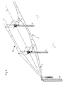
- FIG. 1 to 4 An embodiment of the subject invention is in the Fig. 1 to 4 shown.
- Fig. 1 shows in a side view of the track profile and a mast with boom construction in the lowered position, that is capable of electric driving
- Fig. 2 the same content of Fig. 1 , but with swung-up boom construction for loading operation
- Fig. 3 a detail of the pivotable mast head in perspective
- Fig. 4 an arrangement of masts with lowered and swung-up catenary in perspective view.
- Fig. 1 shows a boom construction 1 on a mast 2, the catenary 3 via a pressure tube, a strut tube, a support tube, a trailer and in particular a support tube 12 and a rotatably mounted support column 4 for driving in a desired position holds.
- the track system 5 spanned by the boom construction 1 is therefore passable for electrically operated towing vehicles.
- the overhead line 3 prevents this project.
- the clearing of the track system 5 a whole loading zone, such as the loading zone of a gantry crane, is carried out by arranging several masts 2 with pivoting boom construction 1 along the route with one clamping device at the beginning and at the end of the swing-up area.
- the mast spacing for straight track sections is approx. 40-70 m.
- the maximum length of a continuous overhead line 3 is approximately 800 m (overhead line section). Taking into account on both sides of the swivel catenary a mast field for bracing the catenary and a mast field to catenary overlap with the fixed catenary network, each with a minimum mast spacing, there is a usable range for the loading area of about 600 m with a continuous overhead line 3. Larger Lengths for the loading area are obtained, for example, by connecting several upwardly pivotable overhead line sections.
- Fig. 3 shows the structural design of the mast head with the swing-boom structure in detail.
- the angle lever 6 connected to the support column 4 on the load arm preferably has an angle of 135 ° between its two arms.
- the power arm of the angle lever is connected to one end of a linear drive or rotary actuator 7 via a hinge.
- This drive is connected at its base to the mast 2 and here in the embodiment comprises an electric motor 8 with a spindle drive 9. If the spindle in the Retracting 7 retracted, pivots the boom structure 1 with the angle lever 6 in the vertical position, the loading area is collision-free and the loading operation can begin. If the spindle moves out of the pivot drive 7, the boom construction 1 pivots back into the horizontal position and the contact line 3 is again in the position to make electrical contact with a current collector of the electric rail vehicle. Thus trains can drive through.
- the swiveling up and down the arranged along the loading zone, swing-boom structures 1 is started by a synchronous operation and monitoring unit, monitored and stopped when reaching the desired end position again. Furthermore, synchronism and speed of the electric drive motors of the rotary actuator 7 are measured and compared with each other and so, for example, a stoppage or a total failure in the course of a fault of a rotary actuator 7 detected. After detecting an error or the asynchronous run of a. Electric motor 8, all quarter-turn actuators 7 are stopped and signaled an error message. Once the error has been diagnosed and corrected, operation can be resumed and panning performed.
- the control unit provides in the horizontal positioning a release signal for example, manually switching on the power supply of the swing-up line section available. Furthermore, the control unit prevents the presence of a voltage in the high pivoting or swung-up state.
- Fig. 4 shows an arrangement of a tension mast 10 and two masts 2 with swing-boom construction 1.
- Variant A shows the horizontal positioning of the catenary 3 with the boom structure 1, which is used for driving.
- Variant B shows the vertical positioning of the catenary 3 with the boom construction 1, which is required for unloading and loading the freight or container wagons.
Landscapes
- Engineering & Computer Science (AREA)
- Mechanical Engineering (AREA)
- Jib Cranes (AREA)
- Current-Collector Devices For Electrically Propelled Vehicles (AREA)
- Electric Cable Arrangement Between Relatively Moving Parts (AREA)
- Electric Propulsion And Braking For Vehicles (AREA)
Abstract
Description
- Die Erfindung betrifft eine Anordnung zur Lageänderung von Fahrleitungen aus dem Bereich der Versorgung eines Schienenfahrzeuges mit elektrischer Energie, wobei die Fahrleitung mit Hilfe einer Auslegerkonstruktion an Masten neben einer Gleisanlage aufgehängt ist.
- Im Bereich der Eisenbahnen ist heute schon fast das ganze Schienennetz mit einer elektrischen Fahrleitung (auch als Oberleitung bezeichnet) ausgerüstet. Die meisten verkehrenden Lokomotiven werden mit elektrischer Energie angetrieben und Diesellokomotiven verlieren im allgemeinen Fahrbetrieb immer mehr an Bedeutung. Ihr Schwerpunkt liegt beim Verschub. Im Gütertransport werden Container verwendet, welche in der Güterverladung bevorzugt mit sogenannten Portalkränen umgelagert werden. Der Portalkran fährt dabei genau über den Container, ergreift diesen und bringt ihn zu einem gewünschten Lagerplatz bzw. Eisenbahnwaggon.
- Das vertikale Hochheben ist bei Gleisanlagen mit Fahrleitung somit nicht möglich. Auch Hubeinrichtungen anderer Bauart können aus Kollisionsgründen mit der Fahrleitung nicht herangezogen werden. Daher verwendet man für das Verschieben der Güterwaggons im Verladebereich Diesellokomotiven, da diese ohne Fahrleitung betrieben werden können und lässt im Verladebereich die Oberleitung zur Gänze weg. Typische Verladebahnhöfe weisen solche oberleitungslosen Gleiskörper auf. Wenn in einem Bahnhofsbereich ein Gleiskörper nicht permanent dem Verladen gewidmet ist, dann ist es sinnvoll, die Fahrleitung aus dem Verladebereich verlagern zu können.
- Aus der deutschen Offenlegungsschrift
DE 1 803 762 sind Varianten zum Verschieben einer elektrischen Oberleitung bei einer Gleisanlage, über die Breite einer Verladeeinrichtung, z.B. eines Portalkranes für Containerverladung, bekannt. Das Verschieben erfolgt entweder durch Hochziehen oder durch Zusammenfalten einer Auslegerkonstruktion. Bedingt durch die Geometrie der Konstruktion ist ein komplettes Freimachen des Ladebereichs über den Gleisanlagen nicht möglich. - Aus der europäischen Patentschrift
EP 0 489 627 B1 , bzw. aus deren deutscher ÜbersetzungDE 691 01 772 T2 ist eine horizontal schwenkbare Oberleitung bekannt, deren Auslegerkonstruktion in weggeschwenkter Position ebenfalls die Gleisanlage nicht zur Gänze freimacht. - Die Erfindung zielt darauf ab, eine Gleisanlage in einem allfälligen Verladebereich so auszustatten, dass das vertikale Verladen von z.B. Containern mittels Portalkränen oder Hubeinrichtungen und eine durchgehende Traktion von Zügen unter der Verwendung von Elektrolokomotiven abwechselnd möglich sind.
- Dies wird bei einer Anordnung zur Lageänderung von Fahrleitungen durch die Merkmale des Anspruchs 1 erreicht. Bevorzugte Ausgestaltungen sind in den abhängigen Ansprüchen definiert. Die Auslegerkonstruktion ist an den Masten hochschwenkbar. Ein Hochschwenken bzw. vertikales Drehen der Auslegerkonstruktion, gemeinsam mit der Fahrleitung um 90°, ermöglicht ein vollständiges Freimachen des Verladebereiches über den Waggons der Gleisanlage und ein ungehindertes Bewegen und Laden mit Hebezeugen, z.B. eines Portalkranes entlang der Gleise. So gelingt es, aus dem Bahnnetz in einen Güterverladebahnhof mit einer einem Güterzug vorgespannten Elektrolokomotive in eine Verladezone einzufahren, die Energieversorgung abzuschalten, die Fahrleitung hochzuklappen und die Be- und Entladung der Güterwaggons mit einem Hebezeug durchzuführen. Nach erfolgtem Laden kann sogleich, nach Herunterklappen der Auslegerkonstruktion mit der Fahrleitung, mit der in der Ladezone verbliebenen Elektrolokomotive nach Anspeisung der Fahrleitung ausgefahren werden. Es wird somit keine wertvolle Zeit durch den zweifachen Wechsel der Elektrolokomotive auf eine Diesellokomotive im Verladebereich verloren.
- Die Auslegerkonstruktion umfaßt eine Tragsäule, die an einem zweiarmigen, am Mast gelagerten Hebel befestigt ist, wobei das Lager insbesondere als Stehlager ausgebildet und auf einer Plattform an einer Mastspitze vorgesehen ist. Die Lagerung umfasst zwei beabstandete Stehlagerböcke, welche in ihrer Drehachse den Hebel aufnehmen. Dabei ist die Auslegerkonstruktion, insbesondere die Tragsäule derselben; mit dem Lastarm und ein linearer Antrieb mit dem Kraftarm des zweiarmigen Hebels verbunden.
- Es ist besonders zweckmäßig, wenn der Hebel als Winkelhebel, mit vorzugsweise 135° Neigungswinkel der Hebelsarme zueinander, ausgeführt ist.
- Eine Ausführungsform sieht vor, dass das Hochschwenken durch einen linearen Antrieb erfolgt, welcher einen Elektromotor mit Spindeltrieb umfasst, wobei bei Anordnung mehrerer Masten mit schwenkbaren Auslegerkonstruktionen, die Antriebe an eine Synchronlaufsteuer- und Überwachungseinheit angeschlossen sind. Besonders wichtig ist die synchrone Ansteuerung der Schwenkantriebe der entlang der Verladezone angeordneten, hochschwenkbaren Auslegerkonstruktionen um ein Reißen der Fahrleitung zu vermeiden. Die Synchronlaufsteuer- und Überwachungseinheit überwacht Gleichlauf und Drehzahl der elektrischen Motore der Schwenkantriebe. Weicht eine Kennzahl deutlich ab, wird das Hochschwenken aller Auslegerkonstruktionen gestoppt und ein Alarm ausgelöst.
- Ein weiteres Merkmal der Erfindung ist, dass die Achsen der Lager für das Hochschwenken und die Position der Spanneinrichtungen an den Enden einer Fahrleitungshalbsektion auf einer Drehachse liegen.
- Durch diese Anordnung erreicht man, dass während des Hochklappens der Auslegerkonstruktion mit der Fahrleitung, diese entlang eines Viertelkreises, dessen Mittelpunkt in der gemeinsamen Drehachse von Stehlager und Position der Spanneinrichtungen am Ende einer Fahrleitungshalbsektion liegen, geführt wird und somit immer der gleiche Abstand zwischen Position der Spanneinrichtungen am Ende einer Fahrleitungshalbsektion und der Fahrleitungsaufhängung an der Auslegerkonstruktion eingehalten wird. Es kommt nicht zum Verziehen und die gesamte Anordnung verhält sich neutral.
- Ein Ausführungsbeispiel des Erfindungsgegenstandes ist in den
Fig. 1 bis 4 dargestellt. -
Fig. 1 zeigt in einer Seitenansicht das Bahnprofil und einen Mast mit Auslegerkonstruktion in der abgesenkten Position, also in der Lage für den elektrischen Fahrbetrieb,Fig. 2 den gleichen Inhalt derFig. 1 , jedoch mit hochgeschwenkter Auslegerkonstruktion für den Ladebetrieb,Fig. 3 ein Detail des schwenkbaren Mastkopfes in perspektivischer Darstellung undFig. 4 eine Anordnung von Masten mit abgesenkter sowie hochgeschwenkter Fahrleitung in perspektivischer Darstellung. -
Fig. 1 zeigt eine Auslegerkonstruktion 1 an einem Mast 2, die die Fahrleitung 3 über ein Druckrohr, ein Strebenrohr, ein Tragrohr, einen Hänger und im Besonderen ein Stützrohr 12 und eine drehbar gelagerte Tragsäule 4 für den Fahrbetrieb in einer gewünschten Position hält. Die von der Auslegerkonstruktion 1 überspannte Gleisanlage 5 ist für elektrisch betriebene Zugfahrzeuge somit befahrbar. - Möchte man in Verladebereichen, wie z.B. in Güterbahnhöfen mit einem Kran, im Besonderen einen Portalkran, Güterwaggons von oben be- und entladen, verhindert die unter Hochspannung stehende Fahrleitung 3 dieses Vorhaben. Wie in
Fig. 2 dargestellt, kann man mit der hochschwenkbaren Auslegerkonstruktion 1 den Bereich über der Gleisanlage 5, bzw. den Güterwaggons, komplett freimachen und ermöglicht dadurch die Ent- und Beladung durch einen Portalkran von oben. Das Freimachen der Gleisanlage 5 einer ganzen Verladezone, z.B. der Ladezone eines Portalkranes, erfolgt durch Anordnung mehrerer Masten 2 mit schwenkbarer Auslegerkonstruktion 1 entlang der Strecke mit jeweils einer Spanneinrichtung am Anfang und am Ende des hochschwenkbaren Bereiches. Der Mastabstand für gerade Gleisstrecken beträgt ca. 40-70 m. Die maximale Länge einer durchgehenden Fahrleitung 3 beträgt ca. 800 m (Fahrleitungshalbsektion). Berücksichtigt man an beiden Seiten des hochschwenkbaren Fahrleitungsbereiches ein Mastfeld zum Abspannen der Fahrleitung und ein Mastfeld zur Fahrleitungsüberlappung mit dem fixen Fahrleitungsnetz, jeweils mit einem minimalen Mastabstand, ergibt sich ein nutzbarer Bereich für den Ladebereich von ca. 600 m mit einer durchgehenden Fahrleitung 3. Größere Längen für den Ladebereich erhält man z.B. durch Hintereinanderschalten mehrerer hochschwenkbarer Fahrleitungshalbsektionen.Fig. 3 zeigt die konstruktive Ausbildung des Mastkopfes mit der hochschwenkbaren Auslegerkonstruktion im Detail. Der mit der Tragsäule 4 am Lastarm verbundene Winkelhebel 6 weist vorzugsweise zwischen seinen beiden Armen einen Winkel von 135° Neigung auf. Der Kraftarm des Winkelhebels ist mit einem Ende eines linearen Antriebes bzw. Schwenkantriebes 7 über ein Gelenk verbunden. Dieser Antrieb ist an seinem Fußpunkt mit dem Mast 2 verbunden und umfasst hier im Ausführungsbeispiel einen Elektromotor 8 mit einem Spindeltrieb 9. Wird die Spindel in den Schwenkantrieb 7 eingefahren, schwenkt die Auslegerkonstruktion 1 mit dem Winkelhebel 6 in die senkrechte Lage, der Ladebereich ist kollisionsfrei und der Ladebetrieb kann beginnen. Fährt die Spindel aus dem Schwenkantrieb 7, schwenkt die Auslegerkonstruktion 1 zurück in die waagrechte Lage und der Fahrleitung 3 ist wieder in der Position, um einen elektrischen Kontakt zu einem Stromabnehmer des elektrischen Schienenfahrzeuges herzustellen. Somit können Züge durchfahren. Das Auf- und Abschwenken der entlang der Verladezone angeordneten, hochschwenkbaren Auslegerkonstruktionen 1 wird durch eine Synchronlaufsteuer- und Überwachungseinheit gestartet, überwacht und beim Erreichen der gewünschten Endposition wieder angehalten. Weiters werden Gleichlauf und Drehzahl der elektrischen Antriebsmotore des Schwenkantriebes 7 gemessen und miteinander verglichen und so z.B. ein Steckenbleiben bzw ein Totalausfall im Zuge einer Störung eines Schwenkantriebes 7 festgestellt. Nach dem Feststellen eines Fehlers bzw. dem asynchronen Lauf eines. Elektromotors 8, werden alle Schwenkantriebe 7 angehalten und eine Fehlermeldung signalisiert. Sobald der Fehler diagnostiziert und behoben ist, kann der Betrieb wieder aufgenommen und ein Schwenken ausgeführt werden. - Die Steuereinheit stellt in der waagrechten Positionierung ein Freigabesignal für das z.B. händische Einschalten der Spannungsversorgung des hochschwenkbaren Leitungsabschnittes zur Verfügung. Des Weiteren verhindert die Steuereinheit das Vorhandensein einer Spannung im hochschwenkenden oder hochgeschwenkten Zustand.
Fig. 4 zeigt eine Anordnung von einem Spannmast 10 und zwei Masten 2 mit hochschwenkbarer Auslegerkonstruktion 1. Variante A zeigt die waagrechte Positionierung der Fahrleitung 3 mit der Auslegerkonstruktion 1, welche für den Fahrbetrieb Verwendung findet. Variante B zeigt die senkrechte Positionierung der Fahrleitung 3 mit der Auslegerkonstruktion 1, welche für Ent- und Beladen der Güter- bzw. Containerwaggons benötigt wird. - Durch die eingezeichnete Drehachse 11 wird verdeutlicht, dass sich die Fahrleitung 3 in einer Kreisbewegung um die Drehachse 11 bewegt, und dass dadurch keine Längenänderung zwischen dem Abspannpunkt des Spannmastes 10 und der hochschwenkbaren Auslegerkonstruktion 1 während des Schwenkens besteht.
- Als weitere Einsatzorte des Erfindungsgegenstandes sind Montage-, Reparatur- und Waschgleise oder Querungen von Gleisen, für die kurzzeitig höhere Durchfahrtshöhen, als der normale Gleis-Fahrleitung-Höhenabstand, erforderlich sind sowohl für elektrische Eisenbahnen als auch Omni-Busse denkbar.
Claims (5)
- Gruppe von Masten (2), die gemeinsam eine
Fahrleitungssektion tragen, mit jeweils einer Anordnung zur Lageänderung von Fahrleitungen (3) aus dem Bereich der versorgung eines Schienenfahrzeuges mit elektrischer Energie, wobei die Fahrleitung (3) mit Hilfe einer Auslegerkonstruktion (1) an den Masten (2) neben einer Gleisanlage (5) aufgehängt ist und die Auslegerkonstruktion (1) an den Masten (2) hochschwenkbar vorgesehen ist,
dadurch gekennzeichnet, dass die Achsen der Lager für das Hochschwenken und die Position der Spanneinrichtungen an den Enden der Fahrleitungssektion auf einer Drehachse (11) liegen. - Gruppe von Masten nach Anspruch 1, dadurch gekennzeichnet, dass bei zumindest einem der Masten (2) die Anordnung einen zweiarmigen Hebel umfasst, dass die Auslegerkonstruktion (1) eine Tragsäule (4), ein Druckrohr und ein Strebenrohr umfasst, wobei die Tragsäule (4) an dem zweiarmigen, am Mast (2) gelagerten Hebel befestigt ist und wobei an der Tragsäule (4) das Druckrohr und das Strebenrohr in Abstand zueinander befestigt sind, und dass das Lager insbesondere als Stehlager ausgebildet und auf einer Plattform an einer Mastspitze vorgesehen ist.
- Gruppe von Masten nach Anspruch 1 oder 2, dadurch gekennzeichnet, dass die Auslegerkonstruktion (1), insbesondere die Tragsäule (4) derselben, mit dem Lastarm und ein linearer Antrieb mit dem Kraftarm des zweiarmigen Hebels verbunden ist.
- Gruppe von Masten nach einem der Ansprüche 1 bis 3, dadurch gekennzeichnet, dass der Hebel als Winkelhebel (6) mit vorzugsweise 135° Neigungswinkel der Hebelarme (2) zueinander ausgeführt ist.
- Gruppe von Masten nach einem der Ansprüche 1 bis 4, dadurch gekennzeichnet, dass der lineare Antrieb für das Hochschwenken einen Elektromotor (8) mit Spindeltrieb (9) (9) umfasst, wobei die Antriebe mehrere Masten an eine Synchronlaufsteuer- und Überwachungseinheit angeschlossen sind.
Applications Claiming Priority (3)
| Application Number | Priority Date | Filing Date | Title |
|---|---|---|---|
| AT0125901A AT409948B (de) | 2001-08-10 | 2001-08-10 | Anordnung zur lageänderung von fahrleitungen |
| AT12592001 | 2001-08-10 | ||
| PCT/AT2002/000237 WO2003013898A1 (de) | 2001-08-10 | 2002-08-07 | Anordnung zur lageänderung von fahrleitungen |
Publications (2)
| Publication Number | Publication Date |
|---|---|
| EP1414667A1 EP1414667A1 (de) | 2004-05-06 |
| EP1414667B1 true EP1414667B1 (de) | 2010-04-28 |
Family
ID=3687883
Family Applications (1)
| Application Number | Title | Priority Date | Filing Date |
|---|---|---|---|
| EP02766915A Expired - Lifetime EP1414667B1 (de) | 2001-08-10 | 2002-08-07 | Anordnung zur lageänderung von fahrleitungen |
Country Status (7)
| Country | Link |
|---|---|
| EP (1) | EP1414667B1 (de) |
| AT (2) | AT409948B (de) |
| DE (1) | DE50214403D1 (de) |
| ES (1) | ES2344406T3 (de) |
| HR (1) | HRPK20040224B3 (de) |
| PL (1) | PL367866A1 (de) |
| WO (1) | WO2003013898A1 (de) |
Families Citing this family (2)
| Publication number | Priority date | Publication date | Assignee | Title |
|---|---|---|---|---|
| SE535969C2 (sv) | 2011-07-29 | 2013-03-12 | Elek Fierade Lastplatser Sverige Ab | Upphängningsarrangemang för en kontaktledning |
| AT517808B1 (de) * | 2015-10-08 | 2018-05-15 | Ing Karl U Albert Kruch Ges M B H & Co Kg | Anordnung zum Halten der aus Tragseil und Fahrdraht bestehenden Oberleitung elektrischer Schienenfahrzeuge |
Family Cites Families (3)
| Publication number | Priority date | Publication date | Assignee | Title |
|---|---|---|---|---|
| DE1803762C3 (de) * | 1968-10-18 | 1975-03-20 | Licentia Patent-Verwaltungs-Gmbh, 6000 Frankfurt | Anordnung von Fahrleitungen in Verladezonen |
| FR2666280B1 (fr) * | 1990-09-04 | 1993-04-30 | Sncf | Dispositif d'alimentation electrique aerienne de vehicules ferroviaires, comportant un conducteur rigide escamotable, et ligne d'alimentation ou ensemble de lignes utilisant au moins un tel dispositif. |
| FR2669868B1 (fr) * | 1990-12-03 | 1993-10-29 | Sncf | Dispositif d'alimentation electrique aerienne de vehicules ferroviaires, a conducteur souple et escamotable horizontalement, et ligne d'alimentation electrique comportant au moins un tel dispositif. |
-
2001
- 2001-08-10 AT AT0125901A patent/AT409948B/de not_active IP Right Cessation
-
2002
- 2002-08-07 EP EP02766915A patent/EP1414667B1/de not_active Expired - Lifetime
- 2002-08-07 PL PL02367866A patent/PL367866A1/xx not_active IP Right Cessation
- 2002-08-07 AT AT02766915T patent/ATE465908T1/de active
- 2002-08-07 HR HR20040224A patent/HRPK20040224B3/xx not_active IP Right Cessation
- 2002-08-07 ES ES02766915T patent/ES2344406T3/es not_active Expired - Lifetime
- 2002-08-07 WO PCT/AT2002/000237 patent/WO2003013898A1/de not_active Ceased
- 2002-08-07 DE DE50214403T patent/DE50214403D1/de not_active Expired - Lifetime
Also Published As
| Publication number | Publication date |
|---|---|
| ATA12592001A (de) | 2002-05-15 |
| WO2003013898B1 (de) | 2004-01-08 |
| ATE465908T1 (de) | 2010-05-15 |
| ES2344406T3 (es) | 2010-08-26 |
| HRPK20040224B3 (hr) | 2006-04-30 |
| DE50214403D1 (de) | 2010-06-10 |
| PL367866A1 (en) | 2005-03-07 |
| AT409948B (de) | 2002-12-27 |
| HRP20040224A2 (en) | 2005-02-28 |
| WO2003013898A1 (de) | 2003-02-20 |
| EP1414667A1 (de) | 2004-05-06 |
Similar Documents
| Publication | Publication Date | Title |
|---|---|---|
| EP0189955B1 (de) | Gleisloses knickgelenktes Untertagefahrzeug mit Elektromotorantrieb | |
| US4016818A (en) | Monorail switch | |
| DE102011076620A1 (de) | Nicht schienengebundenes Fahrzeug | |
| WO2020053084A1 (de) | Stromabnehmer für ein nicht spurgebundenes, elektrisch angetriebenes fahrzeug | |
| DE102008057765A1 (de) | Stromabnehmersystem für ein Fahrzeug, insbesondere für Containerstapelkrane "RTG's" | |
| DE2145828A1 (de) | Maschine mit beweglicher Plattform | |
| EP2955052A1 (de) | Nicht schienengebundenes fahrzeug | |
| EP0819564A2 (de) | Einrichtung für die Stromversorgung einer elektrischen Lokomotive | |
| DE3709619A1 (de) | Duale weichenanordnung zur gemeinsamen benutzung durch spurgefuehrte schienen- und magnetfahrzeuge | |
| CH689420A5 (de) | Laufwerk mit Hebezeug einer Einschienen-Haengebahn. | |
| EP3269582A1 (de) | Nicht schienengebundenes elektrisch oder hybrid-elektrisch angetriebenes fahrzeug | |
| EP3999373A1 (de) | Nicht spurgebundenes fahrzeug mit einem stromabnehmer | |
| DE2834163C2 (de) | Eisenbahnfahrzeug mit einer Umsetzeinrichtung für Behälter | |
| AT409948B (de) | Anordnung zur lageänderung von fahrleitungen | |
| DE102019122471A1 (de) | Stromabnehmer-Anordnung für doppelpolige Fahrdrähte | |
| DE102020000076B3 (de) | Streckenabschnitt für den Betrieb elektrisch angetriebener Schienenfahrzeuge | |
| DE19703282A1 (de) | Kran | |
| DE2911938B2 (de) | Krananlage zum Umschlag von Stückgut | |
| DE1957437A1 (de) | Haengende,elektrisch angetriebene Eisenbahn | |
| DE69101772T2 (de) | Elektrische Oberleitungsversorgungseinrichtung für Schienenfahrzeuge mit einer biegsamen und horizontal schwenkbaren Leitung sowie elektrisches Leistungskabel mit einer solchen Vorrichtung. | |
| DE2807984A1 (de) | Einschienenbahn mit entgleisungssicheren, mittels laufraedern und seitlichen fuehrungselementen auf schienenbalken gefuehrten drehschemeln | |
| EP3568315A1 (de) | Strassengebundenes elektrifiziertes transportsystem | |
| CN210826943U (zh) | 一种道岔 | |
| DE1803762A1 (de) | Anordnung von Fahrleitungen in Verladezonen | |
| DE2707889A1 (de) | Verkehrssystem mit magnetisch getragenen, gefuehrten und angetriebenen fahrzeugen |
Legal Events
| Date | Code | Title | Description |
|---|---|---|---|
| PUAI | Public reference made under article 153(3) epc to a published international application that has entered the european phase |
Free format text: ORIGINAL CODE: 0009012 |
|
| 17P | Request for examination filed |
Effective date: 20040212 |
|
| AK | Designated contracting states |
Kind code of ref document: A1 Designated state(s): AT BE BG CH CY CZ DE DK EE ES FI FR GB GR IE IT LI LU MC NL PT SE SK TR |
|
| AX | Request for extension of the european patent |
Extension state: AL LT LV MK RO SI |
|
| RIN1 | Information on inventor provided before grant (corrected) |
Inventor name: WIMMER, GUENTHER |
|
| RAP1 | Party data changed (applicant data changed or rights of an application transferred) |
Owner name: BICC HOLDINGS GMBH |
|
| GRAP | Despatch of communication of intention to grant a patent |
Free format text: ORIGINAL CODE: EPIDOSNIGR1 |
|
| GRAS | Grant fee paid |
Free format text: ORIGINAL CODE: EPIDOSNIGR3 |
|
| GRAA | (expected) grant |
Free format text: ORIGINAL CODE: 0009210 |
|
| AK | Designated contracting states |
Kind code of ref document: B1 Designated state(s): AT BE BG CH CY CZ DE DK EE ES FI FR GB GR IE IT LI LU MC NL PT SE SK TR |
|
| AX | Request for extension of the european patent |
Extension state: SI |
|
| REG | Reference to a national code |
Ref country code: GB Ref legal event code: FG4D Free format text: NOT ENGLISH |
|
| REG | Reference to a national code |
Ref country code: CH Ref legal event code: EP |
|
| REG | Reference to a national code |
Ref country code: IE Ref legal event code: FG4D Free format text: LANGUAGE OF EP DOCUMENT: GERMAN |
|
| REF | Corresponds to: |
Ref document number: 50214403 Country of ref document: DE Date of ref document: 20100610 Kind code of ref document: P |
|
| REG | Reference to a national code |
Ref country code: SE Ref legal event code: TRGR |
|
| REG | Reference to a national code |
Ref country code: NL Ref legal event code: VDEP Effective date: 20100428 |
|
| REG | Reference to a national code |
Ref country code: ES Ref legal event code: FG2A Ref document number: 2344406 Country of ref document: ES Kind code of ref document: T3 |
|
| PG25 | Lapsed in a contracting state [announced via postgrant information from national office to epo] |
Ref country code: NL Free format text: LAPSE BECAUSE OF FAILURE TO SUBMIT A TRANSLATION OF THE DESCRIPTION OR TO PAY THE FEE WITHIN THE PRESCRIBED TIME-LIMIT Effective date: 20100428 |
|
| REG | Reference to a national code |
Ref country code: IE Ref legal event code: FD4D |
|
| PG25 | Lapsed in a contracting state [announced via postgrant information from national office to epo] |
Ref country code: CY Free format text: LAPSE BECAUSE OF FAILURE TO SUBMIT A TRANSLATION OF THE DESCRIPTION OR TO PAY THE FEE WITHIN THE PRESCRIBED TIME-LIMIT Effective date: 20100428 Ref country code: GR Free format text: LAPSE BECAUSE OF FAILURE TO SUBMIT A TRANSLATION OF THE DESCRIPTION OR TO PAY THE FEE WITHIN THE PRESCRIBED TIME-LIMIT Effective date: 20100729 |
|
| PG25 | Lapsed in a contracting state [announced via postgrant information from national office to epo] |
Ref country code: PT Free format text: LAPSE BECAUSE OF FAILURE TO SUBMIT A TRANSLATION OF THE DESCRIPTION OR TO PAY THE FEE WITHIN THE PRESCRIBED TIME-LIMIT Effective date: 20100830 Ref country code: DK Free format text: LAPSE BECAUSE OF FAILURE TO SUBMIT A TRANSLATION OF THE DESCRIPTION OR TO PAY THE FEE WITHIN THE PRESCRIBED TIME-LIMIT Effective date: 20100428 Ref country code: IE Free format text: LAPSE BECAUSE OF FAILURE TO SUBMIT A TRANSLATION OF THE DESCRIPTION OR TO PAY THE FEE WITHIN THE PRESCRIBED TIME-LIMIT Effective date: 20100428 Ref country code: EE Free format text: LAPSE BECAUSE OF FAILURE TO SUBMIT A TRANSLATION OF THE DESCRIPTION OR TO PAY THE FEE WITHIN THE PRESCRIBED TIME-LIMIT Effective date: 20100428 |
|
| BERE | Be: lapsed |
Owner name: BICC HOLDINGS G.M.B.H. Effective date: 20100831 |
|
| PG25 | Lapsed in a contracting state [announced via postgrant information from national office to epo] |
Ref country code: SK Free format text: LAPSE BECAUSE OF FAILURE TO SUBMIT A TRANSLATION OF THE DESCRIPTION OR TO PAY THE FEE WITHIN THE PRESCRIBED TIME-LIMIT Effective date: 20100428 Ref country code: CZ Free format text: LAPSE BECAUSE OF FAILURE TO SUBMIT A TRANSLATION OF THE DESCRIPTION OR TO PAY THE FEE WITHIN THE PRESCRIBED TIME-LIMIT Effective date: 20100428 |
|
| PLBE | No opposition filed within time limit |
Free format text: ORIGINAL CODE: 0009261 |
|
| STAA | Information on the status of an ep patent application or granted ep patent |
Free format text: STATUS: NO OPPOSITION FILED WITHIN TIME LIMIT |
|
| PG25 | Lapsed in a contracting state [announced via postgrant information from national office to epo] |
Ref country code: MC Free format text: LAPSE BECAUSE OF NON-PAYMENT OF DUE FEES Effective date: 20100831 |
|
| REG | Reference to a national code |
Ref country code: CH Ref legal event code: PL |
|
| 26N | No opposition filed |
Effective date: 20110131 |
|
| PG25 | Lapsed in a contracting state [announced via postgrant information from national office to epo] |
Ref country code: CH Free format text: LAPSE BECAUSE OF NON-PAYMENT OF DUE FEES Effective date: 20100831 Ref country code: LI Free format text: LAPSE BECAUSE OF NON-PAYMENT OF DUE FEES Effective date: 20100831 |
|
| REG | Reference to a national code |
Ref country code: FR Ref legal event code: ST Effective date: 20110502 |
|
| PG25 | Lapsed in a contracting state [announced via postgrant information from national office to epo] |
Ref country code: BE Free format text: LAPSE BECAUSE OF NON-PAYMENT OF DUE FEES Effective date: 20100831 Ref country code: FR Free format text: LAPSE BECAUSE OF NON-PAYMENT OF DUE FEES Effective date: 20100831 |
|
| PG25 | Lapsed in a contracting state [announced via postgrant information from national office to epo] |
Ref country code: BG Free format text: LAPSE BECAUSE OF FAILURE TO SUBMIT A TRANSLATION OF THE DESCRIPTION OR TO PAY THE FEE WITHIN THE PRESCRIBED TIME-LIMIT Effective date: 20100428 Ref country code: LU Free format text: LAPSE BECAUSE OF NON-PAYMENT OF DUE FEES Effective date: 20100807 |
|
| PG25 | Lapsed in a contracting state [announced via postgrant information from national office to epo] |
Ref country code: TR Free format text: LAPSE BECAUSE OF FAILURE TO SUBMIT A TRANSLATION OF THE DESCRIPTION OR TO PAY THE FEE WITHIN THE PRESCRIBED TIME-LIMIT Effective date: 20100428 |
|
| PGFP | Annual fee paid to national office [announced via postgrant information from national office to epo] |
Ref country code: GB Payment date: 20120803 Year of fee payment: 11 |
|
| PGFP | Annual fee paid to national office [announced via postgrant information from national office to epo] |
Ref country code: DE Payment date: 20120810 Year of fee payment: 11 |
|
| PGFP | Annual fee paid to national office [announced via postgrant information from national office to epo] |
Ref country code: AT Payment date: 20120903 Year of fee payment: 11 |
|
| PG25 | Lapsed in a contracting state [announced via postgrant information from national office to epo] |
Ref country code: BG Free format text: LAPSE BECAUSE OF FAILURE TO SUBMIT A TRANSLATION OF THE DESCRIPTION OR TO PAY THE FEE WITHIN THE PRESCRIBED TIME-LIMIT Effective date: 20100728 |
|
| PGFP | Annual fee paid to national office [announced via postgrant information from national office to epo] |
Ref country code: ES Payment date: 20130927 Year of fee payment: 12 |
|
| PGFP | Annual fee paid to national office [announced via postgrant information from national office to epo] |
Ref country code: IT Payment date: 20130827 Year of fee payment: 12 |
|
| REG | Reference to a national code |
Ref country code: AT Ref legal event code: MM01 Ref document number: 465908 Country of ref document: AT Kind code of ref document: T Effective date: 20130807 |
|
| GBPC | Gb: european patent ceased through non-payment of renewal fee |
Effective date: 20130807 |
|
| PG25 | Lapsed in a contracting state [announced via postgrant information from national office to epo] |
Ref country code: DE Free format text: LAPSE BECAUSE OF NON-PAYMENT OF DUE FEES Effective date: 20140301 |
|
| REG | Reference to a national code |
Ref country code: DE Ref legal event code: R119 Ref document number: 50214403 Country of ref document: DE Effective date: 20140301 |
|
| PG25 | Lapsed in a contracting state [announced via postgrant information from national office to epo] |
Ref country code: AT Free format text: LAPSE BECAUSE OF NON-PAYMENT OF DUE FEES Effective date: 20130807 |
|
| PG25 | Lapsed in a contracting state [announced via postgrant information from national office to epo] |
Ref country code: GB Free format text: LAPSE BECAUSE OF NON-PAYMENT OF DUE FEES Effective date: 20130807 |
|
| PG25 | Lapsed in a contracting state [announced via postgrant information from national office to epo] |
Ref country code: IT Free format text: LAPSE BECAUSE OF NON-PAYMENT OF DUE FEES Effective date: 20140807 |
|
| REG | Reference to a national code |
Ref country code: ES Ref legal event code: FD2A Effective date: 20150925 |
|
| PG25 | Lapsed in a contracting state [announced via postgrant information from national office to epo] |
Ref country code: ES Free format text: LAPSE BECAUSE OF NON-PAYMENT OF DUE FEES Effective date: 20140808 |
|
| PGFP | Annual fee paid to national office [announced via postgrant information from national office to epo] |
Ref country code: FI Payment date: 20210830 Year of fee payment: 20 |
|
| PGFP | Annual fee paid to national office [announced via postgrant information from national office to epo] |
Ref country code: SE Payment date: 20210831 Year of fee payment: 20 |
|
| REG | Reference to a national code |
Ref country code: FI Ref legal event code: MAE |
|
| REG | Reference to a national code |
Ref country code: SE Ref legal event code: EUG |