EP1414541B1 - Siebsystem - Google Patents
Siebsystem Download PDFInfo
- Publication number
- EP1414541B1 EP1414541B1 EP02755150A EP02755150A EP1414541B1 EP 1414541 B1 EP1414541 B1 EP 1414541B1 EP 02755150 A EP02755150 A EP 02755150A EP 02755150 A EP02755150 A EP 02755150A EP 1414541 B1 EP1414541 B1 EP 1414541B1
- Authority
- EP
- European Patent Office
- Prior art keywords
- screen
- support
- frame
- mesh
- elements
- Prior art date
- Legal status (The legal status is an assumption and is not a legal conclusion. Google has not performed a legal analysis and makes no representation as to the accuracy of the status listed.)
- Expired - Lifetime
Links
- 238000012216 screening Methods 0.000 claims description 20
- 238000000034 method Methods 0.000 claims description 13
- 230000015572 biosynthetic process Effects 0.000 claims description 10
- 239000007788 liquid Substances 0.000 claims description 6
- 239000012530 fluid Substances 0.000 claims description 5
- 230000003213 activating effect Effects 0.000 claims description 4
- 239000011236 particulate material Substances 0.000 claims description 4
- 238000003780 insertion Methods 0.000 claims description 3
- 230000037431 insertion Effects 0.000 claims description 3
- 238000000926 separation method Methods 0.000 claims description 2
- 239000007787 solid Substances 0.000 claims description 2
- XLYOFNOQVPJJNP-UHFFFAOYSA-N water Substances O XLYOFNOQVPJJNP-UHFFFAOYSA-N 0.000 claims description 2
- 230000008878 coupling Effects 0.000 claims 1
- 238000010168 coupling process Methods 0.000 claims 1
- 238000005859 coupling reaction Methods 0.000 claims 1
- 239000000463 material Substances 0.000 description 17
- 239000002184 metal Substances 0.000 description 10
- 239000010410 layer Substances 0.000 description 7
- 239000004033 plastic Substances 0.000 description 7
- 229920003023 plastic Polymers 0.000 description 7
- 238000005755 formation reaction Methods 0.000 description 6
- 239000000853 adhesive Substances 0.000 description 4
- 230000001070 adhesive effect Effects 0.000 description 4
- 238000013461 design Methods 0.000 description 4
- 238000009434 installation Methods 0.000 description 4
- 230000008569 process Effects 0.000 description 4
- 229910000831 Steel Inorganic materials 0.000 description 3
- 230000008901 benefit Effects 0.000 description 3
- -1 polyethylene Polymers 0.000 description 3
- 238000004080 punching Methods 0.000 description 3
- 230000000717 retained effect Effects 0.000 description 3
- 239000010959 steel Substances 0.000 description 3
- 239000004952 Polyamide Substances 0.000 description 2
- 239000004698 Polyethylene Substances 0.000 description 2
- 238000004873 anchoring Methods 0.000 description 2
- 230000000295 complement effect Effects 0.000 description 2
- 238000010276 construction Methods 0.000 description 2
- 238000005553 drilling Methods 0.000 description 2
- 239000011521 glass Substances 0.000 description 2
- 238000001746 injection moulding Methods 0.000 description 2
- 238000004519 manufacturing process Methods 0.000 description 2
- 230000004048 modification Effects 0.000 description 2
- 238000012986 modification Methods 0.000 description 2
- 229920002647 polyamide Polymers 0.000 description 2
- 229920000573 polyethylene Polymers 0.000 description 2
- 229910001220 stainless steel Inorganic materials 0.000 description 2
- 239000010935 stainless steel Substances 0.000 description 2
- 238000003860 storage Methods 0.000 description 2
- 235000001674 Agaricus brunnescens Nutrition 0.000 description 1
- 229910000906 Bronze Inorganic materials 0.000 description 1
- OKTJSMMVPCPJKN-UHFFFAOYSA-N Carbon Chemical compound [C] OKTJSMMVPCPJKN-UHFFFAOYSA-N 0.000 description 1
- 229920002430 Fibre-reinforced plastic Polymers 0.000 description 1
- 229910001209 Low-carbon steel Inorganic materials 0.000 description 1
- OAICVXFJPJFONN-UHFFFAOYSA-N Phosphorus Chemical compound [P] OAICVXFJPJFONN-UHFFFAOYSA-N 0.000 description 1
- 239000004743 Polypropylene Substances 0.000 description 1
- 230000000712 assembly Effects 0.000 description 1
- 238000000429 assembly Methods 0.000 description 1
- 230000009286 beneficial effect Effects 0.000 description 1
- 239000010974 bronze Substances 0.000 description 1
- 229910052799 carbon Inorganic materials 0.000 description 1
- 239000011248 coating agent Substances 0.000 description 1
- 238000000576 coating method Methods 0.000 description 1
- KUNSUQLRTQLHQQ-UHFFFAOYSA-N copper tin Chemical compound [Cu].[Sn] KUNSUQLRTQLHQQ-UHFFFAOYSA-N 0.000 description 1
- 238000005520 cutting process Methods 0.000 description 1
- 230000006866 deterioration Effects 0.000 description 1
- 230000000694 effects Effects 0.000 description 1
- 239000000835 fiber Substances 0.000 description 1
- 239000011151 fibre-reinforced plastic Substances 0.000 description 1
- 230000003993 interaction Effects 0.000 description 1
- 238000003698 laser cutting Methods 0.000 description 1
- 230000007246 mechanism Effects 0.000 description 1
- 239000000203 mixture Substances 0.000 description 1
- 239000002991 molded plastic Substances 0.000 description 1
- 239000003129 oil well Substances 0.000 description 1
- 238000004806 packaging method and process Methods 0.000 description 1
- 239000006223 plastic coating Substances 0.000 description 1
- 229920000728 polyester Polymers 0.000 description 1
- 229920001155 polypropylene Polymers 0.000 description 1
- 239000002990 reinforced plastic Substances 0.000 description 1
- 238000005096 rolling process Methods 0.000 description 1
- 239000005060 rubber Substances 0.000 description 1
- 238000007789 sealing Methods 0.000 description 1
- 239000002356 single layer Substances 0.000 description 1
- 238000011144 upstream manufacturing Methods 0.000 description 1
- 238000003466 welding Methods 0.000 description 1
Images

Classifications
-
- B—PERFORMING OPERATIONS; TRANSPORTING
- B01—PHYSICAL OR CHEMICAL PROCESSES OR APPARATUS IN GENERAL
- B01D—SEPARATION
- B01D33/00—Filters with filtering elements which move during the filtering operation
- B01D33/01—Filters with filtering elements which move during the filtering operation with translationally moving filtering elements, e.g. pistons
- B01D33/03—Filters with filtering elements which move during the filtering operation with translationally moving filtering elements, e.g. pistons with vibrating filter elements
- B01D33/0346—Filters with filtering elements which move during the filtering operation with translationally moving filtering elements, e.g. pistons with vibrating filter elements with flat filtering elements
- B01D33/0376—Filters with filtering elements which move during the filtering operation with translationally moving filtering elements, e.g. pistons with vibrating filter elements with flat filtering elements supported
-
- B—PERFORMING OPERATIONS; TRANSPORTING
- B07—SEPARATING SOLIDS FROM SOLIDS; SORTING
- B07B—SEPARATING SOLIDS FROM SOLIDS BY SIEVING, SCREENING, SIFTING OR BY USING GAS CURRENTS; SEPARATING BY OTHER DRY METHODS APPLICABLE TO BULK MATERIAL, e.g. LOOSE ARTICLES FIT TO BE HANDLED LIKE BULK MATERIAL
- B07B1/00—Sieving, screening, sifting, or sorting solid materials using networks, gratings, grids, or the like
- B07B1/46—Constructional details of screens in general; Cleaning or heating of screens
- B07B1/48—Stretching devices for screens
- B07B1/49—Stretching devices for screens stretching more than one screen or screen section by the same or different stretching means
Definitions
- the present invention relates to screen systems for use in vibratory screen apparatus suitable for use in liquid solid separation and classification including inter alia, the sifting of drilling mud, cuttings and like material derived from oil-well drilling.
- Hook strip screens generally consist of single or multiple layers of mesh bonded together, which are tensioned after mounting in the basket of the vibratory screen apparatus.
- Two opposed ends of the screen are fitted with a turn back element to form a hook strip which is hooked around a tension rail, the latter being attached to the side wall of the basket, typically via a tension bolt, though other loading means to apply tensioning and securing forces may be employed. Tightening the tension bolt moves the tension rail outwardly, towards the walls of the basket, thus applying tension to the screen.
- the screen is normally stretched over a crowned deck, giving an arcuate profile to the screen, so that rigidity of the screen is retained during vibratory motion.
- Hook strip screens may be pretensioned prior to mounting in the basket by attachment of the screen mesh element to an apertured support plate - typically by means of an adhesive. Where a plurality of mesh layers is used, these would normally be pretensioned. In some designs, layers of fused mesh may be corrugated prior to mounting to an apertured support plate and the hooks applied thereafter to the mesh-plate combination.
- Hook strip screens have a number of disadvantages including the complex and time consuming mounting of the screen members in the basket, which results in significant downtime of the vibratory screen apparatus and requires the use of multiple parts. Attaining the correct screen tension for the material to be sieved also involves intricate fine tuning and the screens are easily damaged if too much force is applied when tightening the bolts or loading means to tension the screens.
- a further disadvantage is the relatively poor sealing between the screen and basket. The metal on metal seal often results in leakage with unscreened material passing through gaps between the screen and the basket, and mixing with already screened material below the mesh screen. Attempts to overcome the poor seal by placing rubber strips or gaskets at the metal/metal interfaces have proved unsatisfactory.
- Pretensioned screens generally comprise one or more layers of mesh permanently bonded under tension onto a generally rigid steel and/or plastics material apertured plate support frame.
- the mesh screen may be flat, or crowned.
- the screen and frame is inserted into the basket as a unit, requiring no adjustment to the tension of the screen.
- the screen and frame unit is normally secured in the machine by clamping it from above or below by, but not restricted to, hydraulic pistons, inflatable clamping bags, bolts, or tapered elements.
- a further problem that arises with known screen systems is that due to the extra weight of the material being processed which is concentrated, in use of screening apparatus at the back (upstream) end thereof.
- the screen mesh in that area is subjected to particularly heavy wear resulting in the frequent need for replacement thereof.
- This problem has previously been addressed by using coarser heavy duty mesh in that area, but this inevitably results in reduced screening performance of the screening apparatus.
- the present invention provides a screen element suitable for use in a vibratory screen apparatus having a screen element support frame provided with spaced apart first and second elongate frame elements and further elongate frame elements extending between said first and second frame elements for supporting the mesh panel of a said screen element, said screen element consisting essentially of a mesh panel provided with first and second elongate support members extending along opposite end portions of said mesh panel, said screen element support members being formed and arranged for secure interengagement with said first and second frame elements, in use of the screen element, with at least one of said screen element support members being formed and arranged so that when clamped to the respective one of said first and second frame elements said mesh panel is securely held under tension against said further frame elements.
- the screen element support members could have a substantially unitary form, or could be in the form of an assembly.
- a first mesh engaging or anchoring, support member portion bonded to a second, clamping force receiving, support member portion by means of adhesive and/or by welding or otherwise fusing together.
- a said first support member portion which is captively interengaged with and/or secured to a said second support member portion using mechanical fastener means such as screws, staples, rivets etc.
- the present invention provides a screen system suitable for use in a vibratory screen apparatus, said screen system comprising:
- both first and second support members and the respective elongate frame elements are formed and arranged for clamping together so as to apply a tensioning force to the screen element to securely hold the mesh panel, under tension against the further frame elements.
- the other may utilise any convenient form of secure interengagement such as one or more hook elements captively engaging in a hook engaging element such as a loop, recess, aperture or the like.
- the hook element(s) may have various different forms such as for example a mushroom shape which can be captively engaged in a keyhole aperture etc.
- the mesh panels may be pretensioned by being secured onto apertured support plates, or may rely on the tensioning forces applied via the support member(s).
- part of the support plate may be used to constitute at least one of the first and second screen element support members.
- an elongate end portion of the support plate could be cranked into a hook form and/or provided with hook or other elements for interengagement with suitable hook engaging elements or the like on the respective one of the first and second frame elements.
- the mesh panel extending between said first and second support members may be in a form of a single continuous area of mesh, or could be made up of a plurality of mesh panel sections interconnected along their adjoining edges by any suitable means such as stitching, bonding, or by releasable interengagement of suitable connectors, for example, ones similar to the hook element type of support member described above. This can be advantageous in order to facilitate handling and installation of the screen elements to the support frames.
- the mesh panelling in a screen system of the invention could be made up of mesh panels of a uniform mesh aperture size and/or shape or, if desired, mesh panels of different mesh size and/or shape could be used. It will also be understood that individual mesh panels could have a uniform mesh aperture size and/or shape or could have a plurality of different mesh aperture sizes and/or shapes, for example, a progression of increasing mesh aperture size from one part to another of the mesh panel. Conveniently mesh panels of variable mesh aperture size could be made by varying the inter-weft and/or inter-warp spacing along or across the weave of a woven mesh panel.
- the apertured support plates could have a uniform aperture size or, if desired, there could be used support plates with apertures of two or more different aperture sizes, for example a series of apertures of progressively increasing aperture size. It will also be understood that, where two or more screen elements are mounted on a single support frame, each of the respective support plates could have a different apertures size and/or shape. Thus individual support plates could have a uniform aperture size and/or shape or could have a plurality of different aperture sizes and/or shapes, for example, a progression of increasing aperture size from one part to another of the plate. It should also be appreciated that where an apertured support plate is used, the mesh secured thereto need not necessarily be pretensioned.
- mesh panels of variable mesh aperture size could be made by varying the inter-weft and/or inter-warp spacing along or across the weave of a woven mesh panel.
- the present invention provides a mesh panel of variable mesh aperture suitable for use in a vibratory screen apparatus.
- a screen system of the present invention there may be used a screen element of particularly simple and economical construction which can be treated as disposable, whilst providing the necessary rigidity and support therefor, in use of the screen system, by means of a said support frame which can readily be reused with successive replacement screen elements.
- a screen element of particularly simple and economical construction which can be treated as disposable, whilst providing the necessary rigidity and support therefor, in use of the screen system, by means of a said support frame which can readily be reused with successive replacement screen elements.
- the screen systems of the invention are generally mounted across the mouth of a basket using a clamping system to secure the screen element and support frame together, on said basket.
- a clamping system may be used which apply a force to said first and second elongate support members of the screen element so as to urge them into contact with respective ones of said first and second frame elements.
- said elongate support members and first and second frame elements are formed and arranged so that when the clamping system is activated to apply said force to said first and second screen support members, said first and second screen support members are urged away from each other so as to tension them across said further frame elements.
- At least one of a clamping force receiving face and a first or second frame element engaging face, of said first and second screen support members is inclined relative to a principal plane of the screen element, so that when a clamping force is applied by said clamping system to said first and second support members, in use of the screen system, said support members are clamped into engagement with said first and second frame elements, and a force component is exerted on each of said support members so as to urge them away from each other.
- a clamping force could instead (or additionally) be applied in a reverse sense i.e. the first and second frame elements are clamped into engagement with said first and second support members (with a force component being exerted on the support members to urge them away from each other as before),
- the securing and support of said screen elements to said support frames can be readily achieved without the need for multiple accessory parts and intricate adjustments and with sufficient security to be retained in the required position use in vibratory screen apparatus despite the high gravitational (G) forces experienced in such use.
- the angle of the inclined face relative to a principal plane of the screen element may be varied so to provide different relative magnitudes of the support member to frame element clamping forces and screen element tensioning forces obtained from a given applied clamping force, when the screen system of the present invention is in use with a vibratory screening apparatus, in order to obtain a desired screen tension etc in any given case etc.
- an angle in the range from 5° to 85°, preferably from 30° to 60°, for example about 45°.
- the support member to frame element clamping force and the screen element tensioning force should generally be selected in the light of the strength of the mesh (and/or any support plate therefor) of the screen element and the vibratory G forces encountered in use of the machine.
- At least one of said first and second screen support members for engagement with said first and second frame elements has a cam portion formed and arranged for interaction with the respective frame element, so that when a clamping force is applied by said clamping system to a clamp force receiving face of said at least one of said first and second support members, in use of the screen system, to clamp said support member(s) into the respective one of said first and second frame elements, a said support member(s) is rotated relative to said frame element, so as to tension the screen element so that the mesh panel is securely held under tension against said further frame elements.
- clamping force could instead (or additionally) be applied in a reverse sense.
- Various suitable clamping systems are known in the art such as hydraulic pistons, inflatable clamping bags, bolts or other screw operated devices, wedging or camming devices, etc. Conveniently the same clamping mechanism is used both to secure the screen system in said basket and to secure said screen support members, and said first and second frame elements, together. Nevertheless separate clamping systems could also be used if desired.
- One particularly suitable form of clamping system comprises a collapsible tube filled with pressurized fluid such as compressed air or a liquid such as water or hydraulic fluid as described in more detail in Patent Publications GB2176424A and GB2176425A .
- the screen system of the present invention can be readily used in existing screen vibratory machinery (of hook-strip and pretensioned design) with clamping systems generally known in the art, with little or no modification, thereby enabling users of existing systems readily to bring it into use at minimal cost.
- the support frame could include additional elongate frame elements and/or further frame elements disposed between said first and second frame elements and further frame elements, in order to provide additional support to the screen mesh panel.
- the screen elements are advantageously provided with readily releasable interengagement elements such as hooks and apertures, for connecting the screen elements together in order to facilitate insertion and withdrawal of the screen elements into and from the screening apparatus.
- the support frames are usually recessed to a greater or lesser degree within the screening apparatus, the support frame is advantageously provided at a proximal end portion thereof with a guide device formed and arranged so that when a screen element is inserted into the screening apparatus it is guided up and over the proximal end of the support frame to avoid fouling thereof.
- the support frame is generally used to support a single screen element.
- a single support frame could be formed and arranged so as to support a plurality of screen elements disposed generally side by side, abutting or cascading across said support frame, supported by additional (intermediate) frame elements between the elongate first and second frame elements.
- Said screen elements may be secured to such intermediate or interior support frame elements by means of hooks, pins.
- a single support frame may be used to support a (single) screen element made up of a plurality of releasably interconnected mesh panel sections, without the need for such intermediate support frame elements.
- the further frame elements extending (transversely) between said first and second frame elements, which support said screen mesh panel when said screen system is secured to the support frame have convexly arcuate support surfaces to form a crown deck, as is customary in the vibratory screen apparatus art, so that the supported screen mesh panel adopts a generally part-cylindrical or part elliptical-section form.
- the support frame may be of any suitable material known in the vibratory screen apparatus art including but not limited to plastics such as glass reinforced polyester and/or polyethylene, polypropylene, polyamide etc. or a blend thereof, metal such as galvanised steel or advantageously stainless steel.
- the mesh panel may be in the form of a plain mesh, or alternatively in a pre-tensioned form in which a mesh is secured e.g. by means of adhesive or fusing, onto or into an apertured lightweight flexible support plate, or plastic coating thereon etc.
- the apertured support plate may be of any suitable material including metal, plastics material, or glass or carbon fibre reinforced plastics, although preferably there is used plastics coated metal, especially plastics coated steel.
- the apertured support plate is manufactured by means of punching suitably sized apertures in the support plate, especially using computer controlled punching apparatus. This has the advantage of affording particular flexibility in relation to the production of support plates with various different aperture sizes (whether within the same support plate or in different support plates).
- the apertures are conveniently formed by producing the apertured support plates by means of techniques such as injection moulding.
- such a bowed plate would be subjected to a process such as rolling so as to take out or reverse to a greater or lesser extent any undesirable bowing, prior to securing the suitably tensioned mesh thereto.
- a process such as rolling so as to take out or reverse to a greater or lesser extent any undesirable bowing, prior to securing the suitably tensioned mesh thereto.
- the mesh panel could comprise a single mesh layer or a plurality of superposed mesh layers which are held together onto said first and second elongate support members.
- the or each mesh panel may be of any suitable form known in the vibratory screen apparatus art depending on the material being screened and other screening conditions. Typically there may be used mesh panels with mesh screen sizes in the range from 10 to 400 (wires per inch) - corresponding to mesh aperture diameters of around 2.5 mm to 0.03 mm.
- the mesh panels are generally fabricated from metal wire, typically of a suitable metal such as stainless steel, phosphor bronze, etc.
- the present invention provides a method of mounting a screen element of the present invention in a vibratory screen apparatus which has a basket provided with screen system support runners formed and arranged for sliding insertion and removal of a screen system of the present invention comprising a said screen element and a support frame therefor, wherein said support runners are provided with at least one clamping device, said method comprising the steps of inserting a said screen element into said basket so as to be supported on a said support frame in said support runners; and activating said at least one clamping device so as to clamp said screen element securely together with said support frame to said support runners.
- runner may be used including support runners in the form of various male and/or female formations on or in the basket sides providing runner surfaces for generally captively supporting the screen element supporting members.
- a support runner in the form of a (female) channel or a pair of parallel (male) flanges.
- the lower runner surfaces of the opposed runners are downwardly inclined towards each other so that when correspondingly inclined engagement surfaces at the underside of the support frame seat thereon, the support frame is automatically centralised in the runner supports of the screening apparatus.
- the present invention provides a vibratory screen apparatus provided with a screen system of the present invention.
- the present invention provides a method of screening a fluidised particulate material suspended in a liquid medium, comprising the steps of providing a vibratory screen apparatus with a screen system of the present invention; mounting the screen element and screen element support frame in an at least one basket of said apparatus so as to be clamped together to said basket; activating a vibratory unit of said vibratory screen apparatus: and feeding said fluidised particulate material onto an upper surface of said screen element.
- the present invention provides a screen mesh panel on a support frame suitable for use in a screen element for a vibratory screening apparatus having the said screen element support frame provided with spaced apart first and second elongate frame elements and further elongate frame elements extending between said first and second frame elements for supporting said mesh panel of said screen element and said screen element consisting (essentially) of a screen mesh panel provided with first and second elongate support members extending along opposite ends of said mesh panel, said screen element support members being formed and arranged for secure interengagement with said first and second frame elements in use of the screen element with at least one of said screen element support members being a clamping force receiving support member formed and arranged so that when clamped to the respective one of said first and second frame elements, said mesh panel is securely held under tension against said further frame elements, said screen mesh panel consisting essentially of at least one mesh layer secured to an apertured support plate and at least one elongate clamping force receiving support member anchorage portion formed and arranged for secure anchoring to the clamping force receiving portion of said support
- clamping force receiving support member anchorage portion may be used.
- an elongate section formation advantageously with at least one enlarged thickness head portion and/or ratchet tooth formation, for push-fit and/or lateral sliding interengagement with a corresponding female formation of the mesh panel clamping force receiving portion of said support member.
- Suitable sections include those illustrated in the accompanying drawings.
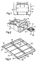
- Fig. 1 shows schematically a vibratory screen apparatus 1 with an outer housing 2 in which is mounted on springs 3 a basket unit 4.
- Each basket 5 of the basket unit 4 (see also Fig. 2 ) is generally box shaped with a pair of circumferentially extending inwardly projecting flanges 6 at an intermediate height on the basket walls 7, for supporting a screen system of the invention 8 as typically found in existing pretension screen vibratory machinery.
- a vibrator unit 9 is secured to the top 10 of the basket unit 4.
- Fig. 4 shows a screen system 8 comprising a screen element 11 clamped to a support frame 12 (also shown in Fig. 3 ) between the basket flanges 6.
- the support frame 12 comprises first and second elongate frame elements 13, 14 at opposite end portions 15, 16 and further elongate, third and fourth, frame elements 17, 18 interconnecting them.
- the screen element 11 comprises a mesh panel 19 having cranked opposite end portions 20, 21 anchored in first and second elongate screen support members 22, 23.
- the screen support members 22, 23 are of generally wedge shaped section with an upper generally horizontally extending clamping force receiving face 24 and a first or second frame element engaging face 25 inclined downwardly at an angle of about 45° thereto (and thus inclined to the generally horizontally extending principal plane of the screen element), for engagement with a correspondingly inclined support face 26 of the first or second frame element 13, 14.
- the support frame 12 with the screen element 11 positioned thereon, is supported at each end portion 15, 16 on a lower one 6a of the respective flanges 6.
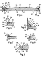
- a clamping device in the form of an inflatable tube 27 is secured 28 to the upper one 6b of the respective flanges 6 so that it extends between the upper flange 6b and the clamping force receiving face 24, so that when the tube 27 is filled with pressurised fluid, it presses down onto said face 24 so as to exert a clamping force C onto the screen element support member 22 and through it onto the respective first or second frame element 13, 14 (see Fig. 5 ).
- the screen element 11 is clamped to the support frame 12, and the screen system 8 comprised thereby is clamped securely to the basket 5.
- the clamping force C comprises a first component 29 normal to the inclined frame element engaging face 25 of the support member 22 and support face 26 of the first (or second) frame element 13 (14) tending to clamp these together, and a second component 30 parallel to these faces 25, 26 tending to slide the support member 22 down the inclined support face 26 of the first (or second) frame element 13 (14). It will be appreciated that this will result in a horizontal force 31 being extended at each end of the screen mesh panel 19 thereby stretching it across the support frame 12.
- the tension applied to the screen mesh panel 19 will depend not only on the clamping force C exerted by the clamping tube 27, but also on the angle of the inclined faces 25, 26 of the frame element 13 and support member 22 and varied to accomodate different screening conditions maximum G force applied by machine and required mesh tension etc. If a steeper angle is used then the first force component 29 will be reduced whilst the second force component 30 is increased.
- the further frame elements 17,18 of the support frame 12 have convexly arcuate upper edges 31 to form a so-called crown deck across which the screen mesh panel 19 is stretched, so as to increase the rigidity and dimensional stability of the mesh panel 19 in use thereof during the vibratory screening process.
- Additional support to the mesh panel 19 is also provided by a series of spaced apart mesh support elements 32 between and parallel to the first and second frame elements 13, 14 as shown in Fig. 3 .
- the further frame elements 17 and 18 are in the form of angle sections 33 to impart greater rigidity to the support frame 12, which is further enhanced by various additional bracing and support elements 34, 35. Since the mesh support elements 32 are subjected to wear from the screen elements which they support, advantageously there are used sacrificial support elements in the form of rods captively mounted in 'C'-shaped recesses, which can be readily replaced as required.
- each basket 5 is formed and arranged to mount therein a plurality of screen systems 8 (only one shown).
- the clamping tube 27 can be simply deflated and the screen system 8 withdrawn, the screen element 11 removed from the support frame 12, and a new screen element 11 put in its place, whereupon the thus restored screen system 8 can be reinstalled and clamped into place.
- the screen system of the present invention is economically beneficial and convenient.
- less material is required for screen system manufacture; storage space requirements, packaging requirements and transport costs of the screens are reduced; and the reduced volume of discarded screen components for disposal has a reduced impact on the environment.
- Fig. 6 shows a screen system and clamping arrangement beyond the scope of the invention in which like parts corresponding to those in the first embodiment are indicated by like reference numerals.
- the support frame 12 has first and second frame elements 40 with a horizontal support face 41 upon which a wedge-section support member 42 of the screen element 11 is supported.
- the support member 42 has a lower horizontal, frame element engaging, face 43 and an upper clamping force receiving face 44 inclined upwardly outwardly of the screen element 11.
- the screen system 8 is supported on a horizontally projecting lower flange 6a as before, but the clamping tube 27 in this case is mounted in an inclined upper flange 6c extending parallel to the inclined clamping force receiving face 44 of the support member 42 so that the clamping force C can be applied normally thereto.
- the resulting clamping and screen tensioning force components 45, 46 are shown in Fig. 7 .
- This arrangement has the advantage of increasing the tensioning force on the screen element and improving control thereof.
- Fig. 8 shows a further modified embodiment similar to that of Figs. 1 to 5 , in which the cranked end portions 20 of the screen mesh panel 19 instead of being anchored in slots within the support members 22, 23 are hooked over the vertically extending outer face 47 of the wedge-section support member 22 - said end portions 20 being made sufficiently rigid to maintain their configuration when the screen mesh panel 19 is fully tensioned.
- the screen mesh panel 19 may be just lightly bonded e.g. with suitable adhesive to the support member 22, or could just rely entirely on the clamping together of the screen mesh panel 19, support members 22, 23 and support frame 12, components of the screen system, when mounted in a basket 5, to retain the screen mesh panel 19 to the support members 22, 23.
- Fig. 9 illustrates yet another screen system beyond the invention in which there is used a support member 51 having a generally wedge shaped profile with an upper side 52 providing a generally horizontal upper clamping force C receiving face and a convex arcuate side 53 providing a cam surface.
- the support member 51 is supported on a step 54 provided on a respective first or second frame element 55 with said cam portion surface 53 engaging with the platform 56 and riser 57 of said step 54.
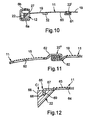
- Fig. 10 shows an embodiment of the present invention where the screen system comprises a plurality of interengaged screen elements at least one of which has a screen support member 22 clamped and secured to an elongated frame element 3 of a support frame 12 between support flanges 6a and 6b of a vibratory screening apparatus basket as described in Fig. 4 .
- the mesh panels 19 of the screen element comprise one or more mesh layers secured to an apertured plate 60 at least two of which have second screen support member 22.
- the second screen support member 22 has an elongated hook for capture engagement in a hook engaging recess 61 of an elongate frame element of said support frame to interengage and secure said screen element to said support frame. Further support for said screen element is provided by additional frame elements 32.
- Fig. 11 is a detail sectional view showing an example of a means for interconnection of two mesh panels 19 of the present invention.
- the other ends of the mesh panels not shown in the figure could be in the form of any of the various support members shown in Figs. 4 to 9 .
- the other end of such a mesh panel 19 could also be in the form of a further mesh panel interconnection means for use in a case where a serial array of 3 or more mesh panels is provided between two support members).
- Fig. 11 shows end portions 62 of two mesh panels 19 having support members hook sections 22.
- the hook sections 22 are formed and arranged so as to maintain the mesh panels 19 in secure interengagement with each other when the screen element 11 is tensioned across the support frame 12.
- Fig. 12 shows part of another embodiment of a screen element 11 in which a mesh panel 19 comprising a wire screen mesh 63 bonded to an apertured support plate 64 is anchored 65 to a clamping force receiving screen support member body 66.
- the end 67 of the apertured plate 64 is cranked downwardly and provided with ratchet tooth formations 68 for push fit locking interengagement in a generally complementary slot 69 in the screen support member body 66, said cranked end 67 effectively constituting a support member anchorage portion, which combines together with the support member body 66 to form together therewith, a support member 22 for the mesh panel 19.
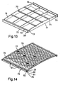
- Fig. 13 shows a support frame generally similar to that of Fig. 3 .
- replacable sacrificial spaced apart mesh support elements 70 mounted in 'C'-section apertures 71 in the third and fourth frame elements 17, 18.
- the first and second frame elements 13, 14 are extended outwardly with an upwardly extending web 72 opposite the inclined face 26, which web 72 is turned back inwardly at its upper edge 73 to form a retaining flange 74.
- Fig. 14 shows a screen element 75 in the form of a mesh panel 76 in which mesh 77 is supported on an apertured support plate 78.
- the support plate 78 is typically of mild steel around 3 mm thick which (in its apertured form) is relatively lightweight and flexible, but nevertheless sufficiently dimensionally stable to support the suitably tensioned mesh 77.
- the latter is secured to the support plate 78 by embedding, in generally known manner, in a polyethylene or polyamide coating which typically has a thickness of the order of 0.5 to 1.2 mm.
- Outer edge portions 79 of the support plate 78 are cranked downwardly and then upwardly to provide an inclined web portion 80 presenting at its underside 81 a first or second frame element engaging face 25, and then an upright web portion 82.
- the upright web portion 82 has secured 83 thereto an 'L'-section angle element 84 which presents a generally horizontally extending clamping force receiving face 24 closely underneath an inflatable clamping tube 27.
- the inclined support face 26 of the first and second frame elements 13, 14, is at a slightly steeper angle than that of the first or second frame element engaging face 25 when the screen element 75 is supported on the third and fourth frame elements 17, 18.
- the outer edge portion 85 of the latter is cutaway slightly to provide a small clearance gap 86 under the support plate 78 thereat.
- the upright web portion 82 of the support plate 78 also has secured 83 thereto low friction guide elements such as small guide discs 87 which are retained captively under the retaining flanges 74 of the support frame 17.
- the guide discs 87 also help to facilitate mounting of the screen element 75 in the support frame 12 and withdrawal therefrom.
- the lower runners 89 could be downwardly inclined towards each other so that when correspondingly inclined engagement surfaces 90 at the underside 91 of the support frame 12 seat thereon, the support frame is automatically centralised in the runner supports of the screening apparatus.
- each basket 5 has a series of screen systems 8 mounted thereover. Normally the support frames 12 remain in position in the apparatus 1 and only the screen elements 11 need to be removed and replaced. In order to facilitate this process, the screen elements 11 are provided at each corner 92 with respective ones of hook 93 and aperture 94 formations so that the screen elements 11 can be releasably interconnected together, as shown in Fig. 16 .
- support members in the form of two or more screen support member components 22a, 22b formed and arranged so as to snap fit together sandwiching the anchor portion edges 95 of the mesh panels 19 therebetween as illustrated in Fig. 17 .
- the anchor portion edges 95 are provided with apertures 96 through which project barbed studs 97 which engage in complementary sockets 98 for secure captive interengagement with each other.
Landscapes
- Chemical & Material Sciences (AREA)
- Chemical Kinetics & Catalysis (AREA)
- Combined Means For Separation Of Solids (AREA)
- Fittings On The Vehicle Exterior For Carrying Loads, And Devices For Holding Or Mounting Articles (AREA)
- Closed-Circuit Television Systems (AREA)
- Liquid Crystal (AREA)
- Eye Examination Apparatus (AREA)
- Transplanting Machines (AREA)
- Preparation Of Compounds By Using Micro-Organisms (AREA)
Claims (17)
- Siebsystem (8) zur Verwendung in einem Korb in einer Vibrationssiebvorrichtung (1), geeignet zur Verwendung bei der Flüssig-Fest-Trennung und Klassierung, wobei der Korb ein Klemmsystem hat, wobei das Siebsystem ein Siebelement (11) auf einem Stützrahmen (12) umfasst,
wobei der Stützrahmen versehen ist mit einem ersten und einem zweiten länglichen Rahmenelement (13, 14), die voneinander entfernt angeordnet sind, und ferner längliche Rahmenelemente (17, 18), die sich zwischen dem ersten und dem zweiten Rahmenelement (13, 14) erstrecken, und zusätzliche längliche Rahmenelemente und/oder weitere Rahmenelemente, die sich in Querrichtung erstrecken (32, 70), einschließt, um eine Kranzplatte zum Stützen der Siebtafel (19) des Siebelements (11) zu bilden,
wobei das Siebelement ein diskretes Bauteil ist, dessen Siebtafel (19) ein vorgespanntes Sieb (77) umfasst, das an einer mit Öffnungen versehenen Stütztafel (78) befestigt ist und mit einem ersten und einem zweiten länglichen Siebstützelement (22, 23) versehen ist, die sich längs gegenüberliegender Endabschnitte der Siebtafel (19) erstrecken, wobei das erste und das zweite Siebstützelement (22, 23) geformt und angeordnet sind für einen sicheren wechselseitigen Eingriff mit dem ersten und dem zweiten Rahmenelement (13, 14) bei Anwendung des Siebelements,
dadurch gekennzeichnet, dass wenigstens das erste und/oder das zweite Siebstützelement (22, 23) eine obere, sich im Allgemeinen in Horizontalrichtung erstreckende Klemmkraftaufnahmefläche (24) und eine Rahmenelementeingriffsfläche (25) einschließt, die dazu nach unten geneigt ist und für einen Eingriff mit einer entsprechend geneigten Stützfläche (26) dient, die an einem jeweiligen von dem ersten und dem zweiten Rahmenelement (13, 14) bereitgestellt wird, so dass, wenn eine Klemmkraft (C) auf die Klemmkraftaufnahmefläche (24) ausgeübt wird, die geneigte Rahmenelementeingriffsfläche (25) des Siebstützelements an die entsprechende geneigte Stützfläche (26) des jeweiligen Rahmenelements geklemmt wird und eine Kraftkomponente ausgeübt wird, die dazu neigt, das Siebstützelement die geneigte Stützfläche (26) des Rahmenelements hinabzuschieben, wodurch die Siebplatte (19) unter Spannung gegen die Kranzplatte gehalten wird, wenn die Stützelemente (22, 23) in wechselseitigem Eingriff mit dem ersten und dem zweiten Rahmenelement (13, 14) befestigt sind. - Siebsystem nach Anspruch 1, wobei die mit Öffnungen versehene Stütztafel (78) Öffnungen in einer Vielzahl von unterschiedlichen Größen und/oder Formen hat.
- Siebsystem nach Anspruch 1 oder Anspruch 2, wobei wenigstens eines der Siebelementstützelemente (22, 23) integral mit der mit Öffnungen versehenen Stütztafel (78) geformt ist.
- Siebsystem nach einem der Ansprüche 1 bis 3, wobei wenigstens eines der Siebelementstützelemente (22, 23) lösbar an der Siebtafel (19) befestigt ist.
- Siebsystem nach einem der Ansprüche 1 bis 4, wobei die Siebtafel (19) mehrere miteinander verbundene Siebtafelsektionen umfasst.
- Siebsystem nach einem der Ansprüche 1 bis 5, wobei jedes der Siebelementstützelemente (22, 23) an wenigstens einem Endabschnitt (92) mit einer lösbaren Eingriffsformation (93, 94) zum Zusammenkoppeln zweier Siebelemente (11) versehen ist, um ein Herausziehen derselben aus einer Vibrationssiebvorrichtung (1) zu erleichtern, die einen Korb (4) hat, der mit einer Reihenanordnung von Siebelementen (11) verwendet wird.
- Siebsystem nach einem der Ansprüche 1 bis 6, wobei sowohl das erste als auch das zweite Siebelementstützelement (22, 23) eine obere, sich im Allgemeinen in Horizontalrichtung erstreckende Klemmkraftaufnahmefläche (24) und eine Rahmenelementeingriffsfläche (25) hat, die dazu nach unten geneigt ist, für einen Eingriff mit entsprechend geneigten Stützflächen (26), die an dem ersten und dem zweiten Rahmenelement (13, 14) bereitgestellt werden, so dass, so dass, wenn eine Klemmkraft (C) auf die Klemmkrafraufnahmefläche (24) ausgeübt wird, eine Kraftkomponente auf jedes Stützelement (22, 23) ausgeübt wird, wodurch sie voneinander weggedrückt werden.
- Siebsystem nach einem der Ansprüche 1 bis 6, wobei das eine von dem ersten und dem zweiten Stützelement (22) und der jeweiligen länglichen Rahmenelemente (13) dafür geformt und angeordnet sind, zusammenzuklemmen, um so eine Spannungskraft auf das Siebelement (11) auszuüben, um die Siebtafel (19) sicher, unter Spannung gegen die Kranzplatte, zu halten, und das andere eine sichere unverlierbare Eingriffseinrichtung umfasst.
- Siebsystem nach einem der Ansprüche 1 bis 6, wobei der Winkel der geneigten Rahnenelementeingriffsfläche (25) der Stützelemente (22, 23), im Verhältnis zu der Hauptebene des Siebelements, von 30° bis 60° beträgt.
- Siebsystem nach einem der Ansprüche 1 bis 9, wobei ein einziger Stützrahmen (12) so geformt und angeordnet ist, dass mehrere Siebelemente (11) stützt, die im Allgemeinen nebeneinander, aneinanderstoßend oder überlappend über den Stützrahmen, angeordnet sind, gestützt durch zusätzliche Zwischenrahmenelemente zwischen dem ersten und dem zweiten länglichen Rahmenelement (13, 14).
- Siebsystem nach einem der Ansprüche 1 bis 10, wobei die Siebtafel (19) mehrere übereinandergelegte Sieblagen umfasst, die auf dem ersten und dem zweiten länglichen Stützelement (22, 23) zusammengehalten werden.
- Siebsystem nach einem der Ansprüche 1 bis 11, wobei das erste und das zweite längliche Rahmenelement (13, 14) im Verhältnis zu dem Stützrahmen (12) unbeweglich sind.
- Siebsystem nach einem der Ansprüche 1 bis 12, wobei die länglichen Stützelemente (22, 23) des Siebelements jeweils einen Verankerungsabschnitt (67) für das Klemmkraftaufhahme-Stützelement haben, der eine längliche Sektionsformation umfasst, mit wenigstens einem Kopfabschnitt mit vergrößerter Dicke und/oder einer Sperrzahnformation (68), für eine Schiebepassung und/oder einen seitlichen wechselseitigen Gleiteingriff mit einer entsprechenden aufnehmenden Formation (69) des Siebplatten-Klemmkraftaufnahmeabschnitts (66) des Stützelements (22, 23).
- Vibrationssiebvorrichtung (1), versehen mit einem Siebsystem nach Anspruch 1, und einem Korb mit einem Klemmsystem, wobei das Klemmsystem dafür verwendet wird, die Siebstützelemente (22, 23) und das erste und das zweite Rahmenelement (13, 14) aneinander zu befestigen und den Stützrahmen (12) des Siebsystems (8) in dem Korb (4) zu befestigen, oder der Stützrahmen (12) gesondert in dem Korb (4) befestigt ist.
- Vibrationssiebvorrichtung (1) nach Anspruch 14, wobei das Klemmsystem eine zusammenlegbare Röhre (27) umfasst, die mit einem unter Druck gesetzten Fluid, wie beispielsweise Druckluft, oder einer Flüssigkeit, wie beispielsweise Wasser oder Hydraulikfluid, gefüllt ist.
- Verfahren zum Anbringen eines Siebsystem (8) nach Anspruch 1 in einer Vibrationssiebvorrichtung (1), die einen Korb (4) hat, der mit Siebsystemstützschienen (6) versehen ist, die für ein gleitendes Einsetzen und Entnehmen eines Siebsystems nach Anspruch 1 geformt und angeordnet sind, umfassend ein Siebelement (11) und einen Stützrahmen (12) für dasselbe, wobei die Stützschienen (6) mit wenigstens einer Klemmeinrichtung (27) versehen sind, wobei das Verfahren die Schritte des Einsetzens eines Siebelements (11) in den Korb (4), so dass es auf einem Stützrahmen (12) in den Stützschienen (6) gestützt wird, und des Aktivierens der wenigstens einen Klemmeinrichtung (27), um so das Siebelement (11) sicher mit dem Stützrahmen (12) zusammen an die Stützschienen (6) zu klemmen, umfasst.
- Verfahren zum Sieben eines in einem flüssigen Medium fluidisierten Feststoffs, dass die Schritte des Bereitstellens einer Vibrationssiebvorrichtung (1) mit einem Siebsystem (8) nach Anspruch 1, des Anbringens des Siebelements (11) und des Siebelement-Stützrahmens (12) in wenigstens einem Korb (4) der Vorrichtung, so dass sie zusammen an den Korb (4) geklemmt werden, des Aktivierens einer Vibrationseinheit (9) der Vibrationssiebvorrichtung und des Zuführens des fluidisierten Feststoffs auf eine obere Fläche des Siebelements (11) umfasst.
Applications Claiming Priority (3)
| Application Number | Priority Date | Filing Date | Title |
|---|---|---|---|
| GB0119523 | 2001-08-10 | ||
| GBGB0119523.9A GB0119523D0 (en) | 2001-08-10 | 2001-08-10 | Screen system |
| PCT/GB2002/003711 WO2003013690A1 (en) | 2001-08-10 | 2002-08-12 | Screen system |
Publications (2)
| Publication Number | Publication Date |
|---|---|
| EP1414541A1 EP1414541A1 (de) | 2004-05-06 |
| EP1414541B1 true EP1414541B1 (de) | 2011-03-30 |
Family
ID=9920169
Family Applications (1)
| Application Number | Title | Priority Date | Filing Date |
|---|---|---|---|
| EP02755150A Expired - Lifetime EP1414541B1 (de) | 2001-08-10 | 2002-08-12 | Siebsystem |
Country Status (11)
| Country | Link |
|---|---|
| US (2) | US7216768B2 (de) |
| EP (1) | EP1414541B1 (de) |
| CN (2) | CN1541131A (de) |
| AT (1) | ATE503542T1 (de) |
| AU (1) | AU2002321447B2 (de) |
| CA (1) | CA2457554C (de) |
| DE (1) | DE60239616D1 (de) |
| EA (1) | EA005486B1 (de) |
| GB (2) | GB0119523D0 (de) |
| NO (1) | NO330613B1 (de) |
| WO (1) | WO2003013690A1 (de) |
Families Citing this family (92)
| Publication number | Priority date | Publication date | Assignee | Title |
|---|---|---|---|---|
| US20040007508A1 (en) | 1999-12-04 | 2004-01-15 | Schulte David L. | Screen assembly for vibratory separator |
| US20050242003A1 (en) | 2004-04-29 | 2005-11-03 | Eric Scott | Automatic vibratory separator |
| GB0301509D0 (en) | 2002-10-17 | 2003-02-19 | Varco Int | Vibratory seperator and screen assembly |
| US8312995B2 (en) | 2002-11-06 | 2012-11-20 | National Oilwell Varco, L.P. | Magnetic vibratory screen clamping |
| US7063214B2 (en) | 2003-02-04 | 2006-06-20 | Varco I/P, Inc. | Interlocking screens for vibratory separators |
| US20060219608A1 (en) * | 2003-02-04 | 2006-10-05 | Eric Scott | Connected screens for vibratory separators |
| GB0302927D0 (en) * | 2003-02-08 | 2003-03-12 | Axiom Process Ltd | Screen mounting system |
| ATE439899T1 (de) | 2003-06-12 | 2009-09-15 | Axiom Process Ltd | Siebvorrichtung |
| US8453844B2 (en) | 2003-06-12 | 2013-06-04 | Axiom Process Ltd. | Screening system |
| US8245850B2 (en) * | 2003-11-13 | 2012-08-21 | Russell Finex Limited | Screen separators |
| US20070267331A1 (en) * | 2004-10-06 | 2007-11-22 | Metso Brasil Ind. E Com. Ltda | Structural Arrangement for Vibrating Equipments |
| AU2005201683B2 (en) * | 2005-04-20 | 2011-02-24 | Flsmidth A/S | A support frame |
| US20070125687A1 (en) * | 2005-12-01 | 2007-06-07 | Kutryk Edward A | Screen assembly for a vibratory separator |
| US20070125688A1 (en) * | 2005-12-06 | 2007-06-07 | Rotex, Inc. | Screening machine, associated screen panel and seal |
| US8261915B2 (en) * | 2005-12-06 | 2012-09-11 | Rotex Global, Llc | Screening machine and associated screen panel |
| US20110036759A1 (en) | 2005-12-06 | 2011-02-17 | Rotex, Inc. | Screening machine and associated screen panel |
| EP1849532B1 (de) * | 2006-04-29 | 2013-08-07 | Dynamic Air Inc. | Vibrationssiebsystem |
| US7891497B2 (en) * | 2006-09-29 | 2011-02-22 | M-I L.L.C. | Peripheral sealing system for pre-tensioned screens |
| US20080083566A1 (en) | 2006-10-04 | 2008-04-10 | George Alexander Burnett | Reclamation of components of wellbore cuttings material |
| US20080223761A1 (en) * | 2007-03-14 | 2008-09-18 | Rotex, Inc. | Sealing Mechanism and Associated Sealing Method for Screening Machines |
| US7578394B2 (en) * | 2007-03-21 | 2009-08-25 | Derrick Corporation | Method and apparatuses for screening |
| US9144825B2 (en) * | 2007-03-21 | 2015-09-29 | Derrick Corporation | Method and apparatuses for screening |
| US9199279B2 (en) * | 2007-03-21 | 2015-12-01 | Derrick Corporation | Method and apparatuses for screening |
| US11338327B2 (en) | 2007-03-21 | 2022-05-24 | Derrick Corporation | Method and apparatuses for screening |
| US8443984B2 (en) * | 2007-03-21 | 2013-05-21 | Derrick Corporation | Method and apparatus for screening |
| US9027760B2 (en) * | 2007-03-21 | 2015-05-12 | Derrick Corporation | Method and apparatuses for screening |
| US9056335B2 (en) * | 2007-03-21 | 2015-06-16 | Derrick Corporation | Method and apparatuses for screening |
| US8622220B2 (en) | 2007-08-31 | 2014-01-07 | Varco I/P | Vibratory separators and screens |
| EA016120B1 (ru) | 2007-10-08 | 2012-02-28 | Эм-Ай ЭлЭлСи | Устройство и способ для распределения жидкости в вибрационном сите |
| US20090179134A1 (en) * | 2008-01-10 | 2009-07-16 | General Kinematics Corporation | Modular deck assembly for a vibratory apparatus |
| CA2807368C (en) | 2008-02-11 | 2016-09-06 | M-I L.L.C. | Preferential bow on composite screens |
| US8270075B2 (en) * | 2008-05-08 | 2012-09-18 | Musion Ip Limited | Projection apparatuses and associated methods |
| GB2461727B (en) * | 2008-07-10 | 2012-06-13 | United Wire Ltd | Improved sifting screen |
| GB0821996D0 (en) | 2008-12-02 | 2009-01-07 | Musion Ip Ltd | Mobile studio |
| GB0910117D0 (en) | 2008-07-14 | 2009-07-29 | Holicom Film Ltd | Method and system for filming |
| US8556083B2 (en) | 2008-10-10 | 2013-10-15 | National Oilwell Varco L.P. | Shale shakers with selective series/parallel flow path conversion |
| US20110000828A1 (en) * | 2008-10-30 | 2011-01-06 | Rotex Global, Llc | Screening machine with segmented screen panels |
| US20100108579A1 (en) * | 2008-10-30 | 2010-05-06 | Rotex Global. Llc | Screening Machine with Segmented Components |
| AU2013205171B2 (en) * | 2009-07-15 | 2017-07-27 | Derrick Corporation | Method and apparatuses for screening |
| US8813970B2 (en) * | 2010-03-19 | 2014-08-26 | M-I L.L.C. | Filter screen with tension element |
| GB2486847B (en) * | 2010-04-29 | 2012-09-26 | Nat Oilwell Varco Lp | Apparatus and method for separating solids from a solids laden drilling fluid |
| GB2479919B (en) | 2010-04-29 | 2012-10-03 | Nat Oilwell Varco Lp | Apparatus and method for separating solids from a solids laden drilling fluid |
| US8869986B2 (en) | 2010-06-25 | 2014-10-28 | Marshall G. Bailey | Screening methods and apparatus |
| GB201010731D0 (en) | 2010-06-25 | 2010-08-11 | Bailey Marshall G | Screening methods and apparatus |
| GB2490647B (en) | 2011-01-27 | 2013-05-22 | Nat Oilwell Varco Lp | Screen assembly and a method for making same |
| GB201106298D0 (en) | 2011-04-13 | 2011-05-25 | Bailey Marshall G | Screen assembly |
| US8800779B2 (en) | 2011-07-05 | 2014-08-12 | Lumsden Corporation | Screen surface forming system |
| WO2013030667A1 (en) | 2011-09-02 | 2013-03-07 | Marshall Graham Bailey | Vibratory screening apparatus |
| MY197347A (en) | 2012-05-25 | 2023-06-14 | Derrick Corp | Injection molded screening apparatuses and methods |
| US10576502B2 (en) | 2012-05-25 | 2020-03-03 | Derrick Corporation | Injection molded screening apparatuses and methods |
| US11161150B2 (en) | 2012-05-25 | 2021-11-02 | Derrick Corporation | Injection molded screening apparatuses and methods |
| US9409209B2 (en) | 2012-05-25 | 2016-08-09 | Derrick Corporation | Injection molded screening apparatuses and methods |
| US9096396B2 (en) * | 2012-06-11 | 2015-08-04 | Babcock Power Services, Inc. | Fluidization and alignment elbow |
| BR112015005591B8 (pt) | 2012-09-12 | 2022-08-02 | Camfil Ab | Tela de suporte, pacote de meio de filtro para um filtro tipo-v e filtro tipo-v possuindo os referidos pacote |
| US9694307B2 (en) | 2012-09-12 | 2017-07-04 | Camfil Ab | Filter assembly and filter assembly manufacturing method |
| EP2897710B1 (de) | 2012-09-21 | 2017-12-06 | Camfil AB | V -typ filter mit unterstützender netzstruktur |
| MX358069B (es) * | 2012-10-16 | 2018-08-03 | Derrick Corp | Metodo y aparatos de filtracion. |
| CN102996836B (zh) * | 2012-10-29 | 2014-12-31 | 南通原亚精密机械有限公司 | 一种震动过滤的腭式闸门 |
| CA2891601A1 (en) | 2012-11-20 | 2014-05-30 | Mpt, Inc. | Advertising media and method and system for applying advertising media |
| US9643111B2 (en) | 2013-03-08 | 2017-05-09 | National Oilwell Varco, L.P. | Vector maximizing screen |
| US9089877B2 (en) * | 2013-03-15 | 2015-07-28 | Michael McGrath, JR. | Backing screen panels for vibrating screen separator |
| US9580175B2 (en) | 2013-04-04 | 2017-02-28 | Franklin Products, Inc. | Aircraft seat back assembly |
| GB2530923B (en) * | 2013-06-14 | 2020-05-20 | Mi Llc | Smart shaker room |
| RU2676103C2 (ru) * | 2013-08-27 | 2018-12-26 | ЭфПи КЭНМИКЭНИКА ИНК. | Двухситная система для соединения с грохотом (варианты) |
| US8978894B1 (en) * | 2013-09-09 | 2015-03-17 | Key Technology, Inc. | Clamp |
| GB201407872D0 (en) | 2014-05-02 | 2014-06-18 | Bailey Marshall G | Screening apparatus and method |
| CN107073523A (zh) * | 2014-09-09 | 2017-08-18 | 基伊埃斯坎维布罗公司 | 筛子设备和为筛子设备的筛网提供卫生支撑的方法 |
| EP3237122A1 (de) | 2014-12-23 | 2017-11-01 | Derrick Corporation | Systeme, vorrichtungen und verfahren zur sicherung von bildschirmanordnungen |
| US20160288171A1 (en) * | 2015-04-02 | 2016-10-06 | Continental Wire Cloth, LLC | Vibratory shaker screen assembly |
| US9764358B2 (en) * | 2015-05-08 | 2017-09-19 | Strox Systems, Llc | Screen assembly for vibratory screening machines |
| CN105413847A (zh) * | 2015-12-09 | 2016-03-23 | 徐妍玲 | 一种粉末涂料粉碎机振动输送的筛料装置 |
| CN105642543A (zh) * | 2015-12-30 | 2016-06-08 | 苏州安特实业有限公司 | 一种振动过滤网架 |
| CN105583964A (zh) * | 2016-02-19 | 2016-05-18 | 德清县联诚氨基塑料制品有限公司 | 一种筛粉机 |
| US11285514B2 (en) * | 2016-05-03 | 2022-03-29 | Schlumberger Technology Corporation | Apparatus, system and method for fastening a screen on a gyratory sifter |
| US20170320096A1 (en) * | 2016-05-03 | 2017-11-09 | M-I Llc | Apparatus, system and method for installing a screen assembly in a gyratory sifter |
| US10391521B2 (en) * | 2016-07-29 | 2019-08-27 | Steve L. Gilbert | Systems and methods for large debris conveyance |
| DE102016011817A1 (de) * | 2016-10-05 | 2018-04-05 | Hein, Lehmann Gmbh | Spannwellensiebmaschine mit optimierter Siebbelagbefestigung |
| US10376924B2 (en) * | 2017-02-23 | 2019-08-13 | Frito-Lay North America, Inc. | Separation apparatus with screen having fixed, non-uniform openings |
| US20180257013A1 (en) * | 2017-03-10 | 2018-09-13 | Grant Young | Shaker screen frame with circular member |
| PE20200680A1 (es) | 2017-04-28 | 2020-06-11 | Derrick Corp | Composiciones termoplasticas, metodos, aparato y usos |
| US11505638B2 (en) | 2017-04-28 | 2022-11-22 | Derrick Corporation | Thermoplastic compositions, methods, apparatus, and uses |
| TR201820225U5 (tr) | 2017-06-06 | 2021-01-21 | Derrick Corp | Eleme usulü ve düzenekleri. |
| US11213857B2 (en) | 2017-06-06 | 2022-01-04 | Derrick Corporation | Method and apparatus for screening |
| CN107433281A (zh) * | 2017-09-09 | 2017-12-05 | 河南地之绿环保科技有限公司 | 一种塑料垃圾处理系统用的分拣设备 |
| US10456810B2 (en) * | 2017-10-27 | 2019-10-29 | M-I L.L.C. | Inflation-activated separator screen |
| GB2570350B (en) * | 2018-01-23 | 2022-11-30 | Terex Gb Ltd | Screening bar assembly for a screen |
| CN108745881A (zh) * | 2018-06-05 | 2018-11-06 | 濉溪博赢橡塑制品有限公司 | 一种煤矿井下用阻燃抗静电耐磨橡胶筛网 |
| CN109351614A (zh) * | 2018-09-03 | 2019-02-19 | 安徽屹翔滤材有限公司 | 一种用于筛板更换的快速替换装置 |
| CN109458145B (zh) * | 2018-12-28 | 2025-01-17 | 默泰克(天津)石油装备有限公司 | 用于开采石油的振动筛网及其制备方法 |
| EP3964302A1 (de) * | 2020-09-02 | 2022-03-09 | Bühler Insect Technology Solutions AG | Spannwellen-siebvorrichtung zur separierung von insekten, insbesondere von insektenlarven, oder von würmern und reststoffen sowie die verwendung einer derartigen spannwellen-siebvorrichtung |
| US11858002B1 (en) * | 2022-06-13 | 2024-01-02 | Continental Wire Cloth, LLC | Shaker screen assembly with molded support rail |
| NL2034261B1 (en) | 2023-03-03 | 2024-09-09 | Rollman Holding B V | A screen assembly for use in a shale shaker |
Citations (8)
| Publication number | Priority date | Publication date | Assignee | Title |
|---|---|---|---|---|
| DE317512C (de) * | ||||
| US1397342A (en) * | 1921-11-15 | Assictob to stubte | ||
| GB368026A (en) * | 1931-02-05 | 1932-03-03 | Salt Union Ltd | Improvements in vibrating sieves |
| US3092573A (en) * | 1961-06-26 | 1963-06-04 | Jordan W Lambert | Vibrating screen clamp mechanism |
| DE1258713B (de) * | 1965-12-14 | 1968-01-11 | Siemag Masch Stahlbau | Schwingsieb mit in einem Siebkasten eingespanntem, zusammen mit diesem in Schwingungen versetztem Siebbelag und mit einer Abklopfvorrichtung |
| US5332101A (en) * | 1992-05-06 | 1994-07-26 | Derrick Manufacturing Corporation | Screen aligning, tensioning and sealing structure for vibratory screening machine |
| US5614094A (en) * | 1994-05-13 | 1997-03-25 | Deister Machine Co., Inc. | Vibrating screen unit |
| US5615776A (en) * | 1992-04-21 | 1997-04-01 | Alfa Laval Separation Ab | Mounting & tensioning arrangements for screens |
Family Cites Families (18)
| Publication number | Priority date | Publication date | Assignee | Title |
|---|---|---|---|---|
| GB554679A (en) | 1942-04-15 | 1943-07-14 | Nordberg Manufacturing Co | Improvements in or relating to screening apparatus |
| US3968053A (en) | 1973-10-12 | 1976-07-06 | Universal Oil Products Company | Catalytic reforming with an activated bimetallic catalytic composite |
| AT329474B (de) * | 1974-02-25 | 1976-05-10 | Oesterr Amerikan Magnesit | Spannvorrichtung fur siebboden |
| DE3517592A1 (de) * | 1984-05-16 | 1985-11-21 | Kanzaki Paper Mfg. Co., Ltd., Tokio/Tokyo | Siebgeraet |
| GB8514983D0 (en) * | 1985-06-13 | 1985-07-17 | Thule United Ltd | Screen clamping |
| GB8514982D0 (en) * | 1985-06-13 | 1985-07-17 | Thule United Ltd | Screen clamping |
| JPH0141510Y2 (de) * | 1986-06-17 | 1989-12-07 | ||
| US5248043A (en) * | 1992-02-28 | 1993-09-28 | Dorn Lloyd A | Modular retro-fit screen system for a screening deck |
| US6371301B1 (en) * | 2000-11-17 | 2002-04-16 | Varco I/P, Inc. | Screen basket for shale shakers |
| US5971159A (en) * | 1993-04-30 | 1999-10-26 | Tuboscope I/P, Inc. | Screen assembly for a vibratory separator |
| CA2201903A1 (en) * | 1994-10-05 | 1996-04-18 | Mats Anders Malmberg | Screen cloth element and screen cloth for making the same |
| DE69415811T2 (de) * | 1994-10-05 | 1999-06-10 | Svedala Trellex Ab, Trelleborg | Siebgeflechtteil |
| AU3100597A (en) | 1996-06-13 | 1998-01-07 | Its Holdings Limited | Apparatus for attaching filter means to a frame |
| DK0963261T3 (da) * | 1997-03-01 | 2003-06-02 | United Wire Ltd | Forbedrert filtersi og støtteramme hertil |
| US20040007508A1 (en) * | 1999-12-04 | 2004-01-15 | Schulte David L. | Screen assembly for vibratory separator |
| US7942272B2 (en) * | 2001-08-10 | 2011-05-17 | Axiom Process Ltd. | Screen system |
| GB0120862D0 (en) * | 2001-08-29 | 2001-10-17 | United Wire Ltd | Method and device for joining screens |
| GB0301509D0 (en) * | 2002-10-17 | 2003-02-19 | Varco Int | Vibratory seperator and screen assembly |
-
2001
- 2001-08-10 GB GBGB0119523.9A patent/GB0119523D0/en not_active Ceased
-
2002
- 2002-08-12 CN CNA028157303A patent/CN1541131A/zh not_active Withdrawn
- 2002-08-12 CN CNB2005100859976A patent/CN100462152C/zh not_active Expired - Lifetime
- 2002-08-12 US US10/486,485 patent/US7216768B2/en not_active Expired - Lifetime
- 2002-08-12 AT AT02755150T patent/ATE503542T1/de not_active IP Right Cessation
- 2002-08-12 WO PCT/GB2002/003711 patent/WO2003013690A1/en not_active Ceased
- 2002-08-12 EA EA200400292A patent/EA005486B1/ru not_active IP Right Cessation
- 2002-08-12 CA CA2457554A patent/CA2457554C/en not_active Expired - Lifetime
- 2002-08-12 DE DE60239616T patent/DE60239616D1/de not_active Expired - Lifetime
- 2002-08-12 AU AU2002321447A patent/AU2002321447B2/en not_active Ceased
- 2002-08-12 EP EP02755150A patent/EP1414541B1/de not_active Expired - Lifetime
- 2002-08-12 GB GB0401552A patent/GB2393137B/en not_active Expired - Lifetime
-
2004
- 2004-03-09 NO NO20041021A patent/NO330613B1/no not_active IP Right Cessation
-
2007
- 2007-03-22 US US11/689,692 patent/US7850011B2/en not_active Expired - Lifetime
Patent Citations (8)
| Publication number | Priority date | Publication date | Assignee | Title |
|---|---|---|---|---|
| DE317512C (de) * | ||||
| US1397342A (en) * | 1921-11-15 | Assictob to stubte | ||
| GB368026A (en) * | 1931-02-05 | 1932-03-03 | Salt Union Ltd | Improvements in vibrating sieves |
| US3092573A (en) * | 1961-06-26 | 1963-06-04 | Jordan W Lambert | Vibrating screen clamp mechanism |
| DE1258713B (de) * | 1965-12-14 | 1968-01-11 | Siemag Masch Stahlbau | Schwingsieb mit in einem Siebkasten eingespanntem, zusammen mit diesem in Schwingungen versetztem Siebbelag und mit einer Abklopfvorrichtung |
| US5615776A (en) * | 1992-04-21 | 1997-04-01 | Alfa Laval Separation Ab | Mounting & tensioning arrangements for screens |
| US5332101A (en) * | 1992-05-06 | 1994-07-26 | Derrick Manufacturing Corporation | Screen aligning, tensioning and sealing structure for vibratory screening machine |
| US5614094A (en) * | 1994-05-13 | 1997-03-25 | Deister Machine Co., Inc. | Vibrating screen unit |
Also Published As
| Publication number | Publication date |
|---|---|
| EA005486B1 (ru) | 2005-02-24 |
| DE60239616D1 (de) | 2011-05-12 |
| US20040238434A1 (en) | 2004-12-02 |
| CA2457554C (en) | 2012-05-29 |
| US7216768B2 (en) | 2007-05-15 |
| ATE503542T1 (de) | 2011-04-15 |
| NO20041021L (no) | 2004-03-09 |
| EA200400292A1 (ru) | 2004-06-24 |
| GB0119523D0 (en) | 2001-10-03 |
| US7850011B2 (en) | 2010-12-14 |
| CA2457554A1 (en) | 2003-02-20 |
| CN100462152C (zh) | 2009-02-18 |
| CN1541131A (zh) | 2004-10-27 |
| GB2393137B (en) | 2004-12-22 |
| CN1736620A (zh) | 2006-02-22 |
| GB0401552D0 (en) | 2004-02-25 |
| NO330613B1 (no) | 2011-05-30 |
| WO2003013690A1 (en) | 2003-02-20 |
| AU2002321447B2 (en) | 2007-10-25 |
| HK1082459A1 (zh) | 2006-06-09 |
| EP1414541A1 (de) | 2004-05-06 |
| US20070187303A1 (en) | 2007-08-16 |
| GB2393137A (en) | 2004-03-24 |
Similar Documents
| Publication | Publication Date | Title |
|---|---|---|
| EP1414541B1 (de) | Siebsystem | |
| US7942272B2 (en) | Screen system | |
| AU2002321447A1 (en) | Screen system | |
| US7478728B2 (en) | Screen system | |
| US6032806A (en) | Screen apparatus for vibratory separator | |
| EP1098688B1 (de) | Flachsiebschirm für kronbodenrüttler | |
| CA2502296C (en) | Vibratory separator and screen assembly | |
| EP1781424B1 (de) | Siebanordnung entworfen um sich dem radius schwingender schüttelsiebe mit gekrümmten tragflächen anzupassen | |
| US12208419B2 (en) | Compression apparatuses, systems and methods for screening materials | |
| CA2576823C (en) | Screen assembly and shale shaker | |
| US6029824A (en) | Screen for vibrating separator | |
| AU2025201813A1 (en) | Compression apparatuses, systems and methods for screening materials | |
| US20170100747A1 (en) | Screen tensioning system and method | |
| CA2240693C (en) | Screen for vibrating separator | |
| US11858002B1 (en) | Shaker screen assembly with molded support rail | |
| HK1082459B (en) | Screen system, screen component and its installation method, vibrating screen device and particle screening method | |
| EP1708826B1 (de) | Verfahren zur Befestigung einer Siebanordnung auf einem Siebrahmen einer Vibrationstrennvorrichtung | |
| CA2513332C (en) | Screen for vibrating separator | |
| TR2025005027T2 (tr) | Malzemelerin elenmesi için sıkıştırma aparatları, sistemleri ve usulleri | |
| TR2025005065A2 (tr) | Malzemelerin elenmesi için sıkıştırma aparatları, sistemleri ve usulleri | |
| MXPA00012123A (en) | Flat screen panel for crowned deck vibrating shaker |
Legal Events
| Date | Code | Title | Description |
|---|---|---|---|
| PUAI | Public reference made under article 153(3) epc to a published international application that has entered the european phase |
Free format text: ORIGINAL CODE: 0009012 |
|
| 17P | Request for examination filed |
Effective date: 20040129 |
|
| AK | Designated contracting states |
Kind code of ref document: A1 Designated state(s): AT BE BG CH CY CZ DE DK EE ES FI FR GB GR IE IT LI LU MC NL PT SE SK TR |
|
| AX | Request for extension of the european patent |
Extension state: AL LT LV MK RO SI |
|
| 17Q | First examination report despatched |
Effective date: 20070111 |
|
| GRAP | Despatch of communication of intention to grant a patent |
Free format text: ORIGINAL CODE: EPIDOSNIGR1 |
|
| GRAS | Grant fee paid |
Free format text: ORIGINAL CODE: EPIDOSNIGR3 |
|
| GRAA | (expected) grant |
Free format text: ORIGINAL CODE: 0009210 |
|
| AK | Designated contracting states |
Kind code of ref document: B1 Designated state(s): AT BE BG CH CY CZ DE DK EE ES FI FR GB GR IE IT LI LU MC NL PT SE SK TR |
|
| REG | Reference to a national code |
Ref country code: GB Ref legal event code: FG4D |
|
| REG | Reference to a national code |
Ref country code: CH Ref legal event code: EP |
|
| REG | Reference to a national code |
Ref country code: IE Ref legal event code: FG4D |
|
| REF | Corresponds to: |
Ref document number: 60239616 Country of ref document: DE Date of ref document: 20110512 Kind code of ref document: P |
|
| REG | Reference to a national code |
Ref country code: DE Ref legal event code: R096 Ref document number: 60239616 Country of ref document: DE Effective date: 20110512 |
|
| REG | Reference to a national code |
Ref country code: NL Ref legal event code: VDEP Effective date: 20110330 |
|
| PG25 | Lapsed in a contracting state [announced via postgrant information from national office to epo] |
Ref country code: GR Free format text: LAPSE BECAUSE OF FAILURE TO SUBMIT A TRANSLATION OF THE DESCRIPTION OR TO PAY THE FEE WITHIN THE PRESCRIBED TIME-LIMIT Effective date: 20110701 Ref country code: SE Free format text: LAPSE BECAUSE OF FAILURE TO SUBMIT A TRANSLATION OF THE DESCRIPTION OR TO PAY THE FEE WITHIN THE PRESCRIBED TIME-LIMIT Effective date: 20110330 |
|
| PG25 | Lapsed in a contracting state [announced via postgrant information from national office to epo] |
Ref country code: AT Free format text: LAPSE BECAUSE OF FAILURE TO SUBMIT A TRANSLATION OF THE DESCRIPTION OR TO PAY THE FEE WITHIN THE PRESCRIBED TIME-LIMIT Effective date: 20110330 Ref country code: CY Free format text: LAPSE BECAUSE OF FAILURE TO SUBMIT A TRANSLATION OF THE DESCRIPTION OR TO PAY THE FEE WITHIN THE PRESCRIBED TIME-LIMIT Effective date: 20110330 Ref country code: FI Free format text: LAPSE BECAUSE OF FAILURE TO SUBMIT A TRANSLATION OF THE DESCRIPTION OR TO PAY THE FEE WITHIN THE PRESCRIBED TIME-LIMIT Effective date: 20110330 |
|
| PG25 | Lapsed in a contracting state [announced via postgrant information from national office to epo] |
Ref country code: BE Free format text: LAPSE BECAUSE OF FAILURE TO SUBMIT A TRANSLATION OF THE DESCRIPTION OR TO PAY THE FEE WITHIN THE PRESCRIBED TIME-LIMIT Effective date: 20110330 |
|
| PG25 | Lapsed in a contracting state [announced via postgrant information from national office to epo] |
Ref country code: EE Free format text: LAPSE BECAUSE OF FAILURE TO SUBMIT A TRANSLATION OF THE DESCRIPTION OR TO PAY THE FEE WITHIN THE PRESCRIBED TIME-LIMIT Effective date: 20110330 Ref country code: PT Free format text: LAPSE BECAUSE OF FAILURE TO SUBMIT A TRANSLATION OF THE DESCRIPTION OR TO PAY THE FEE WITHIN THE PRESCRIBED TIME-LIMIT Effective date: 20110801 |
|
| PG25 | Lapsed in a contracting state [announced via postgrant information from national office to epo] |
Ref country code: CZ Free format text: LAPSE BECAUSE OF FAILURE TO SUBMIT A TRANSLATION OF THE DESCRIPTION OR TO PAY THE FEE WITHIN THE PRESCRIBED TIME-LIMIT Effective date: 20110330 Ref country code: SK Free format text: LAPSE BECAUSE OF FAILURE TO SUBMIT A TRANSLATION OF THE DESCRIPTION OR TO PAY THE FEE WITHIN THE PRESCRIBED TIME-LIMIT Effective date: 20110330 Ref country code: ES Free format text: LAPSE BECAUSE OF FAILURE TO SUBMIT A TRANSLATION OF THE DESCRIPTION OR TO PAY THE FEE WITHIN THE PRESCRIBED TIME-LIMIT Effective date: 20110711 |
|
| PG25 | Lapsed in a contracting state [announced via postgrant information from national office to epo] |
Ref country code: NL Free format text: LAPSE BECAUSE OF FAILURE TO SUBMIT A TRANSLATION OF THE DESCRIPTION OR TO PAY THE FEE WITHIN THE PRESCRIBED TIME-LIMIT Effective date: 20110330 |
|
| PLBE | No opposition filed within time limit |
Free format text: ORIGINAL CODE: 0009261 |
|
| STAA | Information on the status of an ep patent application or granted ep patent |
Free format text: STATUS: NO OPPOSITION FILED WITHIN TIME LIMIT |
|
| PG25 | Lapsed in a contracting state [announced via postgrant information from national office to epo] |
Ref country code: DK Free format text: LAPSE BECAUSE OF FAILURE TO SUBMIT A TRANSLATION OF THE DESCRIPTION OR TO PAY THE FEE WITHIN THE PRESCRIBED TIME-LIMIT Effective date: 20110330 |
|
| 26N | No opposition filed |
Effective date: 20120102 |
|
| PG25 | Lapsed in a contracting state [announced via postgrant information from national office to epo] |
Ref country code: MC Free format text: LAPSE BECAUSE OF NON-PAYMENT OF DUE FEES Effective date: 20110831 |
|
| REG | Reference to a national code |
Ref country code: CH Ref legal event code: PL |
|
| REG | Reference to a national code |
Ref country code: DE Ref legal event code: R097 Ref document number: 60239616 Country of ref document: DE Effective date: 20120102 |
|
| PG25 | Lapsed in a contracting state [announced via postgrant information from national office to epo] |
Ref country code: LI Free format text: LAPSE BECAUSE OF NON-PAYMENT OF DUE FEES Effective date: 20110831 Ref country code: CH Free format text: LAPSE BECAUSE OF NON-PAYMENT OF DUE FEES Effective date: 20110831 |
|
| REG | Reference to a national code |
Ref country code: IE Ref legal event code: MM4A |
|
| PG25 | Lapsed in a contracting state [announced via postgrant information from national office to epo] |
Ref country code: IT Free format text: LAPSE BECAUSE OF FAILURE TO SUBMIT A TRANSLATION OF THE DESCRIPTION OR TO PAY THE FEE WITHIN THE PRESCRIBED TIME-LIMIT Effective date: 20110330 |
|
| PG25 | Lapsed in a contracting state [announced via postgrant information from national office to epo] |
Ref country code: IE Free format text: LAPSE BECAUSE OF NON-PAYMENT OF DUE FEES Effective date: 20110812 |
|
| PG25 | Lapsed in a contracting state [announced via postgrant information from national office to epo] |
Ref country code: LU Free format text: LAPSE BECAUSE OF NON-PAYMENT OF DUE FEES Effective date: 20110812 |
|
| PG25 | Lapsed in a contracting state [announced via postgrant information from national office to epo] |
Ref country code: BG Free format text: LAPSE BECAUSE OF FAILURE TO SUBMIT A TRANSLATION OF THE DESCRIPTION OR TO PAY THE FEE WITHIN THE PRESCRIBED TIME-LIMIT Effective date: 20110630 |
|
| PG25 | Lapsed in a contracting state [announced via postgrant information from national office to epo] |
Ref country code: TR Free format text: LAPSE BECAUSE OF FAILURE TO SUBMIT A TRANSLATION OF THE DESCRIPTION OR TO PAY THE FEE WITHIN THE PRESCRIBED TIME-LIMIT Effective date: 20110330 |
|
| REG | Reference to a national code |
Ref country code: FR Ref legal event code: PLFP Year of fee payment: 15 |
|
| REG | Reference to a national code |
Ref country code: FR Ref legal event code: PLFP Year of fee payment: 16 |
|
| REG | Reference to a national code |
Ref country code: FR Ref legal event code: PLFP Year of fee payment: 17 |
|
| REG | Reference to a national code |
Ref country code: DE Ref legal event code: R082 Ref document number: 60239616 Country of ref document: DE Representative=s name: MARKS & CLERK (LUXEMBOURG) LLP, LU Ref country code: DE Ref legal event code: R081 Ref document number: 60239616 Country of ref document: DE Owner name: NATIONAL OILWELL VARCO UK LIMITED, GB Free format text: FORMER OWNER: AXIOM PROCESS LTD., NEWCASTLE UPON TYNE, GB |
|
| REG | Reference to a national code |
Ref country code: GB Ref legal event code: 732E Free format text: REGISTERED BETWEEN 20210624 AND 20210630 |
|
| PGFP | Annual fee paid to national office [announced via postgrant information from national office to epo] |
Ref country code: FR Payment date: 20210714 Year of fee payment: 20 |
|
| PGFP | Annual fee paid to national office [announced via postgrant information from national office to epo] |
Ref country code: DE Payment date: 20210630 Year of fee payment: 20 Ref country code: GB Payment date: 20210707 Year of fee payment: 20 |
|
| REG | Reference to a national code |
Ref country code: DE Ref legal event code: R071 Ref document number: 60239616 Country of ref document: DE |
|
| REG | Reference to a national code |
Ref country code: GB Ref legal event code: PE20 Expiry date: 20220811 |
|
| PG25 | Lapsed in a contracting state [announced via postgrant information from national office to epo] |
Ref country code: GB Free format text: LAPSE BECAUSE OF EXPIRATION OF PROTECTION Effective date: 20220811 |