EP1414095A2 - Brennstoffzelle mit geteilten Anoden - Google Patents
Brennstoffzelle mit geteilten Anoden Download PDFInfo
- Publication number
- EP1414095A2 EP1414095A2 EP03255963A EP03255963A EP1414095A2 EP 1414095 A2 EP1414095 A2 EP 1414095A2 EP 03255963 A EP03255963 A EP 03255963A EP 03255963 A EP03255963 A EP 03255963A EP 1414095 A2 EP1414095 A2 EP 1414095A2
- Authority
- EP
- European Patent Office
- Prior art keywords
- fuel
- fuel cell
- anode
- exhaust
- segmented
- Prior art date
- Legal status (The legal status is an assumption and is not a legal conclusion. Google has not performed a legal analysis and makes no representation as to the accuracy of the status listed.)
- Withdrawn
Links
Images


Classifications
-
- H—ELECTRICITY
- H01—ELECTRIC ELEMENTS
- H01M—PROCESSES OR MEANS, e.g. BATTERIES, FOR THE DIRECT CONVERSION OF CHEMICAL ENERGY INTO ELECTRICAL ENERGY
- H01M4/00—Electrodes
- H01M4/86—Inert electrodes with catalytic activity, e.g. for fuel cells
-
- H—ELECTRICITY
- H01—ELECTRIC ELEMENTS
- H01M—PROCESSES OR MEANS, e.g. BATTERIES, FOR THE DIRECT CONVERSION OF CHEMICAL ENERGY INTO ELECTRICAL ENERGY
- H01M4/00—Electrodes
- H01M4/86—Inert electrodes with catalytic activity, e.g. for fuel cells
- H01M4/8605—Porous electrodes
-
- H—ELECTRICITY
- H01—ELECTRIC ELEMENTS
- H01M—PROCESSES OR MEANS, e.g. BATTERIES, FOR THE DIRECT CONVERSION OF CHEMICAL ENERGY INTO ELECTRICAL ENERGY
- H01M4/00—Electrodes
- H01M4/86—Inert electrodes with catalytic activity, e.g. for fuel cells
- H01M4/8605—Porous electrodes
- H01M4/8626—Porous electrodes characterised by the form
-
- H—ELECTRICITY
- H01—ELECTRIC ELEMENTS
- H01M—PROCESSES OR MEANS, e.g. BATTERIES, FOR THE DIRECT CONVERSION OF CHEMICAL ENERGY INTO ELECTRICAL ENERGY
- H01M8/00—Fuel cells; Manufacture thereof
- H01M8/002—Shape, form of a fuel cell
-
- H—ELECTRICITY
- H01—ELECTRIC ELEMENTS
- H01M—PROCESSES OR MEANS, e.g. BATTERIES, FOR THE DIRECT CONVERSION OF CHEMICAL ENERGY INTO ELECTRICAL ENERGY
- H01M8/00—Fuel cells; Manufacture thereof
- H01M8/02—Details
- H01M8/0202—Collectors; Separators, e.g. bipolar separators; Interconnectors
- H01M8/0247—Collectors; Separators, e.g. bipolar separators; Interconnectors characterised by the form
-
- H—ELECTRICITY
- H01—ELECTRIC ELEMENTS
- H01M—PROCESSES OR MEANS, e.g. BATTERIES, FOR THE DIRECT CONVERSION OF CHEMICAL ENERGY INTO ELECTRICAL ENERGY
- H01M4/00—Electrodes
- H01M4/86—Inert electrodes with catalytic activity, e.g. for fuel cells
- H01M2004/8678—Inert electrodes with catalytic activity, e.g. for fuel cells characterised by the polarity
- H01M2004/8684—Negative electrodes
-
- H—ELECTRICITY
- H01—ELECTRIC ELEMENTS
- H01M—PROCESSES OR MEANS, e.g. BATTERIES, FOR THE DIRECT CONVERSION OF CHEMICAL ENERGY INTO ELECTRICAL ENERGY
- H01M8/00—Fuel cells; Manufacture thereof
- H01M8/10—Fuel cells with solid electrolytes
- H01M8/12—Fuel cells with solid electrolytes operating at high temperature, e.g. with stabilised ZrO2 electrolyte
- H01M2008/1293—Fuel cells with solid oxide electrolytes
-
- H—ELECTRICITY
- H01—ELECTRIC ELEMENTS
- H01M—PROCESSES OR MEANS, e.g. BATTERIES, FOR THE DIRECT CONVERSION OF CHEMICAL ENERGY INTO ELECTRICAL ENERGY
- H01M8/00—Fuel cells; Manufacture thereof
- H01M8/10—Fuel cells with solid electrolytes
- H01M8/12—Fuel cells with solid electrolytes operating at high temperature, e.g. with stabilised ZrO2 electrolyte
- H01M8/1231—Fuel cells with solid electrolytes operating at high temperature, e.g. with stabilised ZrO2 electrolyte with both reactants being gaseous or vaporised
-
- Y—GENERAL TAGGING OF NEW TECHNOLOGICAL DEVELOPMENTS; GENERAL TAGGING OF CROSS-SECTIONAL TECHNOLOGIES SPANNING OVER SEVERAL SECTIONS OF THE IPC; TECHNICAL SUBJECTS COVERED BY FORMER USPC CROSS-REFERENCE ART COLLECTIONS [XRACs] AND DIGESTS
- Y02—TECHNOLOGIES OR APPLICATIONS FOR MITIGATION OR ADAPTATION AGAINST CLIMATE CHANGE
- Y02E—REDUCTION OF GREENHOUSE GAS [GHG] EMISSIONS, RELATED TO ENERGY GENERATION, TRANSMISSION OR DISTRIBUTION
- Y02E60/00—Enabling technologies; Technologies with a potential or indirect contribution to GHG emissions mitigation
- Y02E60/30—Hydrogen technology
- Y02E60/50—Fuel cells
Definitions
- This invention relates to fuel cells. More particularly, this invention relates a method and apparatus for a fuel cell fuel supply and exhaust manifold.
- Fuel cells conduct an electrochemical energy conversion of hydrogen and oxygen into electricity and heat. Fuel cells are similar to batteries, but they can be “recharged” while providing power.
- Fuel cells provide a DC (direct current) voltage that may be used to power motors, lights, or any number of electrical appliances.
- DC direct current
- Fuel cells are usually classified by the type of electrolyte used.
- the fuel cell types are generally categorized into one of five groups: proton exchange membrane (PEM) fuel cells, alkaline fuel cells (AFC), phosphoric-acid fuel cells (PAFC), solid oxide fuel cells (SOFC), and molten carbonate fuel cells (MCFC).
- PEM proton exchange membrane
- AFC alkaline fuel cells
- PAFC phosphoric-acid fuel cells
- SOFC solid oxide fuel cells
- MCFC molten carbonate fuel cells
- Fuel cells typically include four basic elements: an anode, a cathode, an electrolyte, and a catalyst arranged on each side of the electrolyte.
- the anode is the negative post of the fuel cell and conducts electrons that are freed from hydrogen molecules such that the electrons can be used in an external circuit.
- the anode includes channels to disperse the fuel gas as evenly as possible over the surface of the catalyst.
- the cathode is the positive post of the fuel cell, and typically includes channels etched therein to evenly distribute oxygen (usually air) to the surface of the catalyst.
- the cathode also conducts the electrons back from the external circuit to the catalyst, where they can recombine with the hydrogen ions and oxygen to form water.
- the fuel gas that is directed to the anode utilizes only a small portion of the catalyst area. Accordingly, some of the fuel gas often passes through the fuel cell unconsumed. Further, the exhaust products from the catalytic reaction appear to remain in the catalyst area, requiring the fresh incoming fuel to compete with the exhaust to gain access to the catalyst.
- the present invention provides a fuel cell system including a fuel cell having a plurality of segmented anodes, each segmented anode measuring a minimal length sufficient to substantially consume or catalyze fuel introduced to the anode.
- FIG. 1 is a diagrammatical illustration of a fuel cell system according to one embodiment of the present invention.
- FIG. 2 is a front view of fuel cell structure according to one embodiment of the present invention.
- FIG. 2A is a top view a first layer of a fuel cell manifold according to one embodiment of the present invention.
- FIG. 2B is a top view of a second layer of a fuel cell manifold according to one embodiment of the present invention.
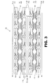
- FIG. 3 is front view of a combination multiple fuel cells according to one embodiment of the present invention.
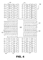
- FIG. 4 is a top view of a fuel cell manifold according to another embodiment of the present invention.
- FIG. 1 an overview of an electronic device (51) using a fuel cell power system is shown according to one embodiment of the present invention.
- a fuel cell (40) in fluid communication with a fuel source, (42).
- the fuel source (42) provides a supply of fuel along a path represented by an arrow (44).
- a supply of oxygen, which may be provided by ambient air, is also in fluid communication with the fuel cell (40) as represented by another arrow (46).
- water (H 2 O) may be produced as a byproduct of the operation of the fuel cell (40).
- the fuel cell (40) may provide power via an external circuit (48) to an electrical load (50).
- the electrical load (50) may include any electrically operated device including, but not limited to, a motor, a light, a digital camera, a laptop computer, and other devices consuming electricity.
- the external circuit (48) may also be connected to an optional voltage regulator/control circuit (51) and an electrical capacitor or battery (52), which are shown in electrical parallel with the fuel cell (40).
- the optional voltage regulator/control circuit (51) may include a feedback loop (53) for providing data to the fuel source (42).
- the electrical capacitor or battery (52) may provide auxiliary power to the electrical load (50).
- the fuel cell (40) may include a structure that enhances the utilization of a fuel cell anode catalyst.
- FIG. 2 the fuel cell (40) structure according to one embodiment of the present invention is shown.
- the fuel cell (40) may be a solid oxide fuel cell. SOFCs advantageously allow for the use of a variety of fuels (e.g., hydrogen, hydrocarbons, alcohols, etc.).
- the fuel cell (40) includes four basic elements: an anode (20), a cathode (22), an electrolyte (24), and a manifold system (26).
- the anode or anode segments (20) and the cathode (22) are arranged on either side of the electrolyte (24).
- the anode (20) is the negative post of the fuel cell (40) and conducts electrons that are freed from the fuel to the external circuit (48, FIG. 1).
- the cathode (22) is the positive post of the fuel cell, and is exposed to an oxygen supply (usually near ambient air pressure).
- the cathode need not be segmented, but it can be if desired.
- the cathode (22) also conducts the electrons back from the external circuit, where they combine with molecular oxygen to form oxygen ions.
- the electrolyte (24) of the present embodiment is a solid oxide membrane (24).
- the membrane (24) is typically a high temperature ceramic material that conducts only oxygen ions. This membrane (24) also prevents the passage of electrons.
- the anode (20) includes a ceramic/metal mixture (cermet) (e.g., yttria stabilized zirconia/nickel; samaria doped ceria/nickel, etc.).
- the anode (20) may also include other or alternative materials based on the particular fuel cell application.
- the anode (20) is porous so as to maximize the three-phase boundary.
- the three-phase boundary defines an edge at which the fuel (e.g. hydrogen), the anode (20), and the electrolyte (24) meet.
- the anode (20) may include the ceramic/metal mixtures mentioned above which act as a catalytic agent to facilitate the oxidation of the fuel.
- the cathode (22) may include a composite mixture of an electrocatalyst and oxygen ion conductor (e.g., lanthanum strontium maganate/yttria stabilized zirconia, samarium strontium cobaltite/samaria doped ceria, etc.).
- the cathode (22) may be porous so as to maximize the three-phase boundary, but this is not necessarily so. Oxygen ions can then combine with the fuel to form a water molecule (in the present embodiment).
- the cathode (22) materials facilitate the reduction of the oxidant.
- the anode (20), cathode (22), and electrolyte (24), as shown in the embodiment of FIG. 2, are arranged in an arch configuration.
- the arch configuration shown includes first and second angled members (25 and 27), and a generally planar member (29).
- Each of the anode (20), cathode (22), and electrolyte (24) include the first and second angled members (25 and 27) and the generally planar member (29).
- the linear dimension of the anode (20) is approximately two to fifteen millimeters in length.
- the linear dimension of the anode (20) is no more than fifteen millimeters, and, in other embodiments, the linear dimension is no more than five millimeters.
- the linear dimension of the anode (20) is not limited to the ranges listed above.
- the linear dimension of the anode (20) is preferably minimally sized such that substantially all the anode (20) is utilized to substantially consume or catalyze all of the fuel introduced to the anode (20) or fuel cell (40).
- minimally sized may also include some additional length as a margin.
- linear dimension indicates the total length of the anode measured along a straight line from a first end (45) to a second end (47).
- the relatively small linear dimensions of the anode (20) facilitate more complete utilization of the anode (20) in catalyzing the fuel.
- first and second angled members (25 and 27) extend from the manifold system (26).
- the manifold system (26) includes first and second layers (31 and 33) as shown in FIG. 2. However, in alternative embodiments, there may be only a first layer (31). Further, in some embodiments there may be three or more layers.
- First and second layers (31 and 33) are patternable substrate materials such as alumina, metal, ceramic, glass, photo-imageable polymer, or other materials. First and second layers (31 and 33) may be made of the same or different materials.
- the anode (20) and the substrate (33) define a volume in which the chemical reaction of the fuel cell takes place.
- the use of patternable substrate materials for the first and second layers (31 and 33) advantageously facilitates the creation of a fluid communication path including a precise fuel flow path (35) and an exhaust flow path (37).
- the first layer (31) may be patterned in a first direction such as a direction substantially normal to the page at element number (35).
- the pattern in the first direction normal to the page may be variable or tapered, (i.e. progressively larger or smaller), to ensure an even distribution of fuel to each of the fuel cells (40).
- a tapered path may be sized such that the fluid pressure along the full distance of the path is substantially equal.
- the fuel flow path may also be patterned with spokes in a horizontal direction indicated by a first arrow (39) leading to the anodes (27).
- the second layer may be patterned in a second direction such as the substantially vertical direction indicated by a second arrow (41).
- the fuel flow pattern in the second direction (41) is in an opposite direction from the exhaust flow path (37) to facilitate fast and efficient removal of produced exhaust from the anode (20) area.
- the fuel flow path (35) may also continue in the direction normal to the page as a fuel header supplying many fuel cells aligned behind the one shown.
- FIGS. 2A and 2B show from a top view perspective the first and second layers (31 and 33) according to one embodiment of the invention.
- the first layer (31) is shown in FIG. 2A and displays a number of fuel flow paths (35) in an array with a number of spokes (43) extending in the direction of the arrow (39) shown in FIG. 2.
- the spokes (43) lead to individual fuel cell anode segments (20, FIG. 2).
- the exhaust flow path (37) is also shown, with one flow path (37) paired with each spoke (43) to remove exhaust from the fuel cell anode (20, FIG. 2) soon after (within a few seconds or less) by-products are created.
- FIG. 2B illustrates the second layer (33) in top view. As shown, the exhaust flow path (37) and the fuel flow path (41) are arrayed in a multi-cell configuration to match the pattern in first layer (31 ).
- the patterns in the first and second layers (31 and 33) may be created in any of a number of ways, depending on the patternable material used.
- the patterns may be created by drilling or etching to form fluid channels.
- some patternable materials may be sacrificial substrates that are photosensitive. Photosensitive materials such as photo-resistant polymers change in chemical composition when exposed to ultraviolet or other light sources. Therefore, such materials may be exposed to a select pattern of ultraviolet light, and then bathed in a solution known to dissolve either the exposed or unexposed pattern material (but not both) to leave the desired channels. Patterns may also be created in other ways known to those of skill in the art having the benefit of this disclosure.
- the exhaust flow path (37) is also created by patterning the first and second layers (31 and 33). However, according to the present embodiment the exhaust flow path (37) is patterned in a single coaxial third direction (in the present embodiment substantially vertical) through both the first and second layers (31 and 33).
- the flow path (37) may be representative of an array of paths (See FIG. 2B) to fluidly communicate with other fuel cells located behind the one shown to form an exhaust header.
- the exhaust flow path (37) may be patterned in other directions in some embodiments as well.
- the exhaust flow path (37) advantageously provides an outlet in the opposite direction of the fuel inlet for quick removal of the exhaust generated in the anode segment (20) area during fuel cell (40) operation.
- the fuel flow path (35), in combination with the exhaust flow path (37), advantageously provides for both the introduction of fresh fuel to the fuel cell (40) and the removal of spent fuel from the anode (20).
- This flow path arrangement of the fuel flow path (35) and the exhaust flow path (37) facilitates enhanced utilization of a catalytic anode surface (49, FIG. 2) by reducing competition between the fresh fuel and the exhaust for access to the catalyst surface (49, FIG. 2).
- the anode (20) is substantially shorter than conventional planar anode lengths to more efficiently use the catalyst surface (49, FIG. 2).
- a fuel cell may include many smaller minimal anode segments (20) that are each more fully utilized to substantially consume all of the fuel as compared to conventional anodes that only utilize a fraction of their surface area to catalyze the fuel. Further, the short fuel path across the anode segments (20) provides for quick removal of any exhaust byproducts that may otherwise compete with the fresh fuel for access to the anode (20).
- the cathode (22) may be segmented in the same manner as the anode segments (20); it may be planar and shared by many anode segments (20).
- FIG. 3 a stack arrangement of many fuel cells (40) is shown according to another embodiment of the present invention.
- four fuel cell rows (100/102/104/106) are arranged in sets of six cells each, for a total of twenty-four individual fuel cells (40).
- the arrangement of FIG. 3 is, however, exemplary in nature and it is not limited to four rows of six cells each. Further, it is not necessary that each row have an equal number of cells. Any other fuel cell arrangement calculated to meet certain power requirements may also be used with the fuel cells (40) structured in the arch configuration shown with the manifold system (26) in place.
- the manifold system (26) is arranged such that the first and second fuel cell rows (100 and 102) are adjacent to a common air header (108) that supplies oxygen to both of the fuel cell rows (100 and 102).
- a similar arrangement between the third and fourth fuel cell rows (104 and 106) allows the use of another common air header (110).
- a common set of fuel headers (111) of the manifold system (26) may supply fuel to the first row (100) of fuel cells (40).
- Similar fuel headers (112 and 114) may supply fuel to each row of fuel cells.
- Each of the fuel cells (40) includes the fuel flow path (35) and exhaust flow path (37), shown in detail with reference to FIG. 2, to facilitate the manifolding of fuel sources and exhaust products.
- rows of fuel cells such as the second and third rows (102 and 104) can be adjacently arranged as shown with a common exhaust header (116) to remove exhaust from the fuel cells (40).
- Each of the fuel cells (40) is fluidly connected to the manifold system (26) to remove exhaust therefrom.
- FIG. 3 suffers from a reduction in anode surface area as compared to conventional fuel cell planar structures.
- conventional planar fuel cell structures experience under-utilization of anode catalytic surface area that results in inefficient operation of the fuel cell (40).
- the structure shown in FIG. 3 more than compensates for any lost anode surface area by gaining full or near-full utilization of the arched anode surface area (49, FIG. 2).
- the enhanced utilization of the arched anode surface area (49, FIG. 2) is facilitated by a short linear dimension and the removal of exhaust from the anode (20) area to the exhaust manifold (116).
- the operation of the fuel cells (40) can be described generaiiy as follows.
- the fuel e.g., hydrocarbon, H 2 , carbon monoxide, etc.
- the fuel travels through the fuel flow paths (35) where it is introduced to the anodes (20).
- the catalytic anode (20) When the fuel comes into contact with the catalytic anode (20), ions, electrons, and by-products (exhaust) are formed.
- the electrons are conducted through the anode (20), where they make their way through an external circuit that may be providing power to do useful work (such as turning a motor or lighting a bulb) and return to the cathode (22) side of the fuel cells (40).
- anode (20) where they make their way through an external circuit that may be providing power to do useful work (such as turning a motor or lighting a bulb) and return to the cathode (22) side of the fuel cells (40).
- the manifold system (26) as fuel is continually supplied to the fuel cell, the by-products exit the fuel cell (40) though the exhaust flow path (37) and to the exhaust header (116). Therefore, the fresh fuel supply is not required to compete with the exhaust for access to the anode (20).
- the cathode (22) may include one or more advanced catalytic materials such as doped cobaltites, manganites, and ferrites to facilitate the dissociation of oxygen molecules.
- O 2 interacts with the catalytic cathode (22), it forms two oxygen ions, each having a strong negative charge. These oxygen ions pass through the solid oxide electrolyte (24) and oxidize the fuel at the anode (20).
- the oxygen ions combine with the hydrocarbon to produce water, carbon dioxide, and electrons for the external circuit.
- H 2 as the fuel
- the oxygen ions combine to form a water molecule and two electrons for the external circuit.
- Solid oxide fuel cells typically operate at fairly high temperatures (above approximately 800° C), which allow them to have high reaction kinetics, and use a variety of fuels depending on the anode composition. Lower temperature operation is desired for applications that require rapid startup, where inexpensive containment structures, and temperature management is of concern.
- the fuel cell (40) structure shown may be used in other fuel cells as well, including, but not limited to PEM, AFC, PAFC, and MCFC.
- FIG. 4 an alternative arrangement for the fuel cell manifolding system is shown.
- a manifold system (126) arranged in a hub-and-spoke configuration.
- a main fuel artery (128) with a plurality of spokes (130) extending therefrom.
- the spokes (130) and fluid paths may be arranged in the same manner as shown with reference to FIGs. 2A and 2B.
- the number of spokes attached to the fuel artery (128) may be any convenient number and is not limited to the configuration shown in FIG. 4.
- the hub-and-spoke manifold system (126) facilitates a single fuel supply line (e.g. the fuel artery (128)) for supplying fuel to an array of fuel cells, as well as providing fast and efficient removal of exhaust from the system (126) via exhaust flow paths (137).
Applications Claiming Priority (2)
| Application Number | Priority Date | Filing Date | Title |
|---|---|---|---|
| US264395 | 1994-06-23 | ||
| US10/264,395 US20040067406A1 (en) | 2002-10-03 | 2002-10-03 | Fuel cell manifold |
Publications (2)
| Publication Number | Publication Date |
|---|---|
| EP1414095A2 true EP1414095A2 (de) | 2004-04-28 |
| EP1414095A3 EP1414095A3 (de) | 2004-11-10 |
Family
ID=32042212
Family Applications (1)
| Application Number | Title | Priority Date | Filing Date |
|---|---|---|---|
| EP03255963A Withdrawn EP1414095A3 (de) | 2002-10-03 | 2003-09-23 | Brennstoffzelle mit geteilten Anoden |
Country Status (6)
| Country | Link |
|---|---|
| US (2) | US20040067406A1 (de) |
| EP (1) | EP1414095A3 (de) |
| JP (1) | JP4391183B2 (de) |
| KR (1) | KR20040031620A (de) |
| CA (1) | CA2439999A1 (de) |
| TW (1) | TW200406078A (de) |
Families Citing this family (3)
| Publication number | Priority date | Publication date | Assignee | Title |
|---|---|---|---|---|
| EP1609199A2 (de) * | 2003-02-24 | 2005-12-28 | Koninklijke Philips Electronics N.V. | Elektrochemische energiequelle und eine solche energiequelle enthaltende elektronische einrichtung |
| US20060246331A1 (en) * | 2005-04-29 | 2006-11-02 | Steinbroner Matthew P | Partitioned fuel cell stacks and fuel cell systems including the same |
| US8304136B2 (en) * | 2009-09-10 | 2012-11-06 | Samsung Electro-Mechanics Co., Ltd. | Solid oxide fuel cell and solid oxide fuel cell bundle |
Citations (2)
| Publication number | Priority date | Publication date | Assignee | Title |
|---|---|---|---|---|
| EP0505186A1 (de) * | 1991-03-20 | 1992-09-23 | Ngk Insulators, Ltd. | Festelektrolytbrennstoffzelle |
| WO1999044254A1 (en) * | 1998-02-27 | 1999-09-02 | Corning Incorporated | Flexible inorganic electrolyte fuel cell design |
Family Cites Families (12)
| Publication number | Priority date | Publication date | Assignee | Title |
|---|---|---|---|---|
| US5635039A (en) * | 1993-07-13 | 1997-06-03 | Lynntech, Inc. | Membrane with internal passages to permit fluid flow and an electrochemical cell containing the same |
| US6149810A (en) * | 1994-11-23 | 2000-11-21 | Lynntech, Inc. | Membrane with supported internal passages |
| US5918505A (en) * | 1994-12-23 | 1999-07-06 | Linak A/S | Linear actuator and method of making a linear actuator |
| US5549983A (en) * | 1996-01-22 | 1996-08-27 | Alliedsignal Inc. | Coflow planar fuel cell stack construction for solid electrolytes |
| US6054228A (en) * | 1996-06-06 | 2000-04-25 | Lynntech, Inc. | Fuel cell system for low pressure operation |
| WO1998035398A1 (de) * | 1997-02-11 | 1998-08-13 | Bossel Ulf G | Brennstoffzellenstapel mit festen elektrolyten und deren anordnung |
| US5770327A (en) * | 1997-08-15 | 1998-06-23 | Northwestern University | Solid oxide fuel cell stack |
| AU1409200A (en) * | 1998-11-26 | 2000-06-13 | Nippon Ferrule Co., Ltd. | Optical fiber connector and ferrule used for it and production method for ferrule |
| US6159629A (en) * | 1998-12-17 | 2000-12-12 | Ballard Power Systems Inc. | Volume effecient layered manifold assembly for electrochemical fuel cell stacks |
| KR100341402B1 (ko) * | 1999-03-09 | 2002-06-21 | 이종훈 | 고체산화물 연료전지의 단전지와 스택구조 |
| JP3427003B2 (ja) * | 1999-03-31 | 2003-07-14 | 株式会社東芝 | 燃料電池 |
| US6403247B1 (en) * | 1999-12-03 | 2002-06-11 | International Fuel Cells, Llc | Fuel cell power plant having an integrated manifold system |
-
2002
- 2002-10-03 US US10/264,395 patent/US20040067406A1/en not_active Abandoned
-
2003
- 2003-09-05 CA CA002439999A patent/CA2439999A1/en not_active Abandoned
- 2003-09-15 TW TW092125358A patent/TW200406078A/zh unknown
- 2003-09-23 EP EP03255963A patent/EP1414095A3/de not_active Withdrawn
- 2003-09-30 JP JP2003340422A patent/JP4391183B2/ja not_active Expired - Fee Related
- 2003-10-02 KR KR1020030068697A patent/KR20040031620A/ko not_active Application Discontinuation
-
2004
- 2004-06-30 US US10/883,331 patent/US20040241527A1/en not_active Abandoned
Patent Citations (2)
| Publication number | Priority date | Publication date | Assignee | Title |
|---|---|---|---|---|
| EP0505186A1 (de) * | 1991-03-20 | 1992-09-23 | Ngk Insulators, Ltd. | Festelektrolytbrennstoffzelle |
| WO1999044254A1 (en) * | 1998-02-27 | 1999-09-02 | Corning Incorporated | Flexible inorganic electrolyte fuel cell design |
Also Published As
| Publication number | Publication date |
|---|---|
| EP1414095A3 (de) | 2004-11-10 |
| KR20040031620A (ko) | 2004-04-13 |
| JP4391183B2 (ja) | 2009-12-24 |
| JP2004127941A (ja) | 2004-04-22 |
| US20040067406A1 (en) | 2004-04-08 |
| TW200406078A (en) | 2004-04-16 |
| US20040241527A1 (en) | 2004-12-02 |
| CA2439999A1 (en) | 2004-04-03 |
Similar Documents
| Publication | Publication Date | Title |
|---|---|---|
| EP1517392B1 (de) | Zellenbaugruppe des fest-hochpolymertyps | |
| US6926985B2 (en) | Fuel cell stack | |
| US6893766B2 (en) | Methodology for supply of reactant fluids to and purging of product and inert fluids from cells of fuel cell stack | |
| EP2643876B1 (de) | Gleichstrom-/gegenstrombrennstoffzelle oder elektrolysezelle | |
| JP5057634B2 (ja) | 燃料電池構体 | |
| EP1995814B1 (de) | Brennstoffzellenstapel | |
| US7014929B2 (en) | Fuel cell | |
| US7122257B2 (en) | Fuel cell reactant supply | |
| EP1414095A2 (de) | Brennstoffzelle mit geteilten Anoden | |
| KR102371397B1 (ko) | 단계식 연료 공급을 갖는 고체 산화물 연료 전지용 시스템 및 방법 | |
| KR101135481B1 (ko) | 연료 전지용 스택과 이를 갖는 연료 전지 시스템 | |
| CN116391280A (zh) | 燃料电池发电系统以及燃料电池发电系统的控制方法 | |
| KR20060034426A (ko) | 연료 전지 시스템 |
Legal Events
| Date | Code | Title | Description |
|---|---|---|---|
| PUAI | Public reference made under article 153(3) epc to a published international application that has entered the european phase |
Free format text: ORIGINAL CODE: 0009012 |
|
| AK | Designated contracting states |
Kind code of ref document: A2 Designated state(s): AT BE BG CH CY CZ DE DK EE ES FI FR GB GR HU IE IT LI LU MC NL PT RO SE SI SK TR |
|
| AX | Request for extension of the european patent |
Extension state: AL LT LV MK |
|
| PUAL | Search report despatched |
Free format text: ORIGINAL CODE: 0009013 |
|
| AK | Designated contracting states |
Kind code of ref document: A3 Designated state(s): AT BE BG CH CY CZ DE DK EE ES FI FR GB GR HU IE IT LI LU MC NL PT RO SE SI SK TR |
|
| AX | Request for extension of the european patent |
Extension state: AL LT LV MK |
|
| RIC1 | Information provided on ipc code assigned before grant |
Ipc: 7H 01M 8/12 B Ipc: 7H 01M 8/24 A |
|
| 17P | Request for examination filed |
Effective date: 20050505 |
|
| AKX | Designation fees paid |
Designated state(s): DE FR GB |
|
| 17Q | First examination report despatched |
Effective date: 20070730 |
|
| GRAP | Despatch of communication of intention to grant a patent |
Free format text: ORIGINAL CODE: EPIDOSNIGR1 |
|
| STAA | Information on the status of an ep patent application or granted ep patent |
Free format text: STATUS: THE APPLICATION IS DEEMED TO BE WITHDRAWN |
|
| 18D | Application deemed to be withdrawn |
Effective date: 20101120 |