EP1413944A2 - Electronic apparatus with liquid cooling of a heat-generating component - Google Patents
Electronic apparatus with liquid cooling of a heat-generating component Download PDFInfo
- Publication number
- EP1413944A2 EP1413944A2 EP03016725A EP03016725A EP1413944A2 EP 1413944 A2 EP1413944 A2 EP 1413944A2 EP 03016725 A EP03016725 A EP 03016725A EP 03016725 A EP03016725 A EP 03016725A EP 1413944 A2 EP1413944 A2 EP 1413944A2
- Authority
- EP
- European Patent Office
- Prior art keywords
- heat
- pump
- housing
- coolant
- inlet port
- Prior art date
- Legal status (The legal status is an assumption and is not a legal conclusion. Google has not performed a legal analysis and makes no representation as to the accuracy of the status listed.)
- Withdrawn
Links
Images




Classifications
-
- G—PHYSICS
- G06—COMPUTING OR CALCULATING; COUNTING
- G06F—ELECTRIC DIGITAL DATA PROCESSING
- G06F1/00—Details not covered by groups G06F3/00 - G06F13/00 and G06F21/00
- G06F1/16—Constructional details or arrangements
- G06F1/20—Cooling means
- G06F1/203—Cooling means for portable computers, e.g. for laptops
-
- G—PHYSICS
- G06—COMPUTING OR CALCULATING; COUNTING
- G06F—ELECTRIC DIGITAL DATA PROCESSING
- G06F2200/00—Indexing scheme relating to G06F1/04 - G06F1/32
- G06F2200/20—Indexing scheme relating to G06F1/20
- G06F2200/201—Cooling arrangements using cooling fluid
-
- G—PHYSICS
- G06—COMPUTING OR CALCULATING; COUNTING
- G06F—ELECTRIC DIGITAL DATA PROCESSING
- G06F2200/00—Indexing scheme relating to G06F1/04 - G06F1/32
- G06F2200/20—Indexing scheme relating to G06F1/20
- G06F2200/203—Heat conductive hinge
Definitions
- the present invention relates to an electronic apparatus of the liquid-cooled type, in which a heat-generating component such as a CPU is cooled with liquid coolant. More particularly, the invention relates to a structure of a circulation path of the liquid coolant.
- a CPU is incorporated in, for example, notebook-type portable computers.
- the heat that the CPU generates while operating is increasing as its data-processing speed rises, and it performs more and more functions.
- cooling systems of the liquid-cooling type have been developed in recent years.
- a liquid-cooling system uses a liquid coolant that has a far higher specific heat than air.
- Japanese Patent Application KOKAI Publication No. 7-142886 discloses a cooling system of the liquid-cooling type, configured for use in portable computers.
- the cooling system comprises a heat-receiving header, a heat-radiating header, and a tube for circulating the coolant.
- the heat-receiving header is provided in the housing of a portable computer and thermally connected to the CPU incorporated in the housing.
- the heat-radiating header is provided in the display unit of the portable computer.
- the tube extends from the housing to the display unit of the portable computer. It connects the heat-receiving header and the heat-radiating header. Liquid coolant is circulated between the heat-receiving header and the heat-radiating header.
- the liquid coolant in the heat-receiving header absorbs the heat generated by the CPU. That is, the coolant is heated in the heat-receiving header. The coolant thus heated is transferred via the tube into the heat-radiating header. The heat-radiating header radiates the heat generated by the CPU, as the coolant flows through it. The coolant is therefore cooled in the heat-radiating header. The coolant thus cooled is transferred via the tube, back into the heat-receiving header through the tube. Back in the heat-receiving header, the coolant again absorbs the heat from the CPU. As the coolant is thus circulated, the heat is transmitted from the CPU to the heat-radiating header with high efficiency and the heat-radiating head radiates the heat. This cooling enhances the efficiency of cooling the CPU.
- the tube through which the liquid coolant flows extends between the housing and display unit of the computer.
- the display unit is coupled to the housing and can rotate.
- the tube is made of synthetic resin having sufficient flexibility. Since the tube is made of synthetic resin, the liquid coolant inevitably leaks, and passes through the tube and eventually evaporates. To reduce the wasting of the coolant due to its evaporation outside the tube, it is desirable to make the tube as short as possible.
- the tube coupled to the heat-receiving header meanders, passing around various functional components provided in the housing of the computer.
- the tube is therefore very long. Consequently, the liquid coolant evaporates from the tube in large quantities.
- the coolant liquid must be replenished or replaced with fresh coolant very frequently.
- the maintenance of the cooling system requires much labor and time. If the coolant is not replenished, the efficiency of cooling the CPU will decrease to impair the reliability of the cooling system.
- An object of the present invention is to provide an electronic apparatus in which any heat-generating component can be cooled with high efficiency.
- an electronic apparatus includes a first housing incorporating a heat-generating component.
- a second housing is coupled to the first housing.
- a pump is incorporated into the first housing.
- the pump has a heat-receiving portion thermally connected to the heat-generating component.
- a heat-radiating portion is incorporated into the second housing.
- the heat-radiating portion radiates heat generated by the heat-generating component and has a coolant inlet port and a coolant outlet port.
- a circulation path circulates a liquid coolant between the pump and the heat-radiating portion.
- the circulation path has a first pipe connecting the pump to the coolant inlet port of the heat-radiating portion and a second pipe connecting the pump to the coolant outlet port of the heat-radiating portion.
- the first pipe and the second pipe extend from two adjacent points on the pump, toward a midpoint between the coolant inlet port and the coolant outlet port.
- FIGS. 1 to 4 show a portable computer 1, or an electronic apparatus according to this invention.
- the portable computer 1 comprises a computer main unit 2 and a display unit 3.
- the computer main unit 2 has a housing 4 that is shaped like a flat box.
- the housing 4 comprises a bottom wall 4a, a top wall 4b, a front wall 4c, left and right sidewalls 4d, and a back wall 4e.
- the top wall 4b supports a keyboard 5.
- the top wall 4b has a pair of projections 6a and 6b. The projections 6a and 6b lie behind the keyboard 5 and are spaced apart in the width direction of the housing 4.
- the display unit 3 comprises a display housing 8 and a liquid crystal display panel 9 incorporated in the display housing 8.
- the display housing 8 is shaped like a flat box and has a rectangular opening 10 in the front.
- the liquid crystal display panel 9 has a screen 9a that can display images. The screen 9a is exposed outside the housing 8 through the opening 10.
- the display housing 8 has a hollow leg 11. As FIG. 4 shows, the leg 11 is continuous to the interior of the display housing 8. The leg 11 protrudes from the lower edge of the display housing 8 and lies between the projections 6a and 6b of the housing 4. The leg 11 has two end portions 11a and 11b. The first end portion 11a and the second end portion 11b lie adjacent to the projections 6a and 6b of the housing 4, respectively.
- a pair of hinges 12a and 12b couples the leg 11 to the rear edge of the housing 4.
- the first hinge 12a connects the first projection 6a of the housing 4 and the first end portion 11a of the leg 11.
- the second hinge 12b connects the second projection 6b of the housing 4 and the second end portion 11b of the leg 11.
- the display unit 3 is coupled to the housing 4 and can be rotated between a closed position and an opened position. At the closed position, the display unit 3 lies over the housing 4, covering the keyboard 5. At the opened position, the display unit 3 stands up at the rear edge of the housing 4, exposing the keyboard 5 and the liquid crystal display panel 9.
- the housing 4 contains a printed circuit board 13, a hard disk drive 14, and a CD-ROM drive 15.
- the board 13, hard disk drive 14 and CD-ROM drive 15 are secured on the bottom wall 4a of the housing 4.
- a CPU 16 as a heat-generating component is mounted on the printed circuit board 13.
- the CPU 16 is, for example, a semiconductor package of the ball grid array (BGA) type.
- the CPU 16 is located closer to the left side of the housing 4 than to the middle part thereof. It has a base 17 and an IC chip 18 mounted on the center part of the base 17.
- the IC chip 18 generates much heat as it operates, processing data at high speeds and performing many functions.
- the IC chip 18 needs to be cooled to keep operating in stable conditions.
- the portable computer 1 further comprises a cooling unit 20 of the liquid-cooling type.
- the cooling unit 20 comprises a heat-receiving portion 21 (see FIG. 5), a pump 22, a heat-radiating portion 23, and a circulation path 24.
- the heat-receiving portion 21 is a metal plate larger than the base 17 of the CPU 16 as illustrated in FIG. 5. It covers the IC chip 18 from above. Heat-conductive grease fills the gap between the heat-receiving portion 21 and the IC chip 18, thermally connecting the IC chip 18 to the lower surface of the heat-receiving portion 21.
- the pump 22 is formed integral with the heat-receiving portion 21.
- the pump 22 comprises an impeller 25 and a pump housing 26.
- the impeller 25 is connected to a flat motor 27, which is supported on the pump housing 26.
- the axis R1 of the impeller 25 extends in the direction of thickness of the housing 4.
- the flat motor 27 starts rotating the impeller 25 when the power switch to the portable computer 1 is closed (i.e., when the power is "on") or when the temperature of the CPU 16 rises to a preset value.
- the pump housing 26 is shaped like a flat box. It is made of heat-conductive metal such as aluminum alloy. It has a bottom wall 28, a top wall 29, and eight sidewalls 30a to 30h. The walls 28, 29 and 30a to 30h constitute a pump chamber 31.
- the pump chamber 31 contains the impeller 25.
- the bottom wall 28 of the pump housing 26 is laid on the upper surface of the heat-receiving portion 21.
- the bottom wall 28 is therefore thermally connected to the heat-receiving portion 21.
- the first to eighth sidewalls 30a to 30h are arranged, surrounding the impeller 25 and connecting the edges of the bottom wall 28 to the edges of the top wall 29.
- the sidewalls 30a to 30h extend in lines tangential to the circumference of the impeller 25.
- the pump housing 26 looks like a regular octagon as viewed from the axis R1 of the impeller 25, as is illustrated in FIG. 6.
- the pump housing 26 has a coolant inlet port 32 and a coolant outlet port 33.
- the ports 32 and 33 horizontally extend from the first sidewall 30a of the pump housing 26. They extend parallel to each other and are spaced apart from each other.
- a support member 35 fastens the pump 22 to the upper surface of the printed circuit board 13.
- the support member 35 is a leaf spring and can elastically deform. It opposes the top wall 29 and extends in the diameter of the pump housing 26.
- the support member 35 has a pair of legs 36a and 36b and a pushing projection 37.
- the first leg 36a has been formed by bending one end portion of the member 35 downwards.
- the second leg 36b has been formed by bending the other end portion of the member 35 downwards.
- Both legs 36a and 36b are bent, having an L-shaped cross section.
- the pushing projection 37 lies at the center of the support member 35 and protrudes downwards.
- Screws 39 fasten the legs 36a and 36b of the support member 35 to a pair of stud pins 38 that are secured to the printed circuit board 13. Since the legs 36a and 36b are so fastened to the board 13, the pushing projection 37 abuts on the top wall 29 of the pump housing 26. The projection 37 pushes the heat-receiving portion 21 onto the CPU 16. This is because the portion 21 is formed integral with the pump housing 26. As a result, both the heat-receiving portion 21. and the pump 22 are held on the printed circuit board 13.
- the first leg 36a of the support member 35 is interposed between the coolant inlet port 32 and coolant outlet port 33 of the pump 22. Thanks to this arrangement, the coolant inlet port 32 or the coolant outlet port 33 abuts on the first leg 36a of the support member 35 when the pump 22 moves in the circumferential direction of the pump housing 26. Thus, the second leg 36a serves as a stopper to restrict the motion of the pump 22.
- the pump 22 is offset leftwards from the axis O1 of depth of the housing 4, or a line that passes the midpoint in the width of the housing 4.
- the axis 01 goes across the center of the leg 11 of the display housing 8, which is coupled to the housing 4.
- the coolant inlet port 32 and coolant outlet port 33 of the pump 22 extend backward and slantwise from the first sidewall 30a of the pump housing 26. Thus, they are directed toward the middle part of the junction between the display housing 8 and the housing 4.
- the ports 32 and 33 incline to the axis O1 of depth of the housing 4.
- the heat-radiating portion 23 of the cooling unit 20 lies between the back of the display housing 8 and the liquid crystal display panel 9.
- the heat-radiating portion 23 is a rectangular plate that has almost the same size as the liquid display panel 9.
- the heat-radiating portion 23 comprises two heat-radiating plates 41 and 42. Both heat-radiating plates 41 and 42 are made of metal that excels in heat conductivity. They are laid, one upon the other.
- the first heat-radiating plate 41 has a recess 43.
- the recess 43 opens to the second heat-radiating plate 42. It meanders, covering almost the entire first heat-radiating plate 41.
- the second heat-radiating plate 42 closes the recess 43.
- the recess 43 serves as a coolant path 44, which is defined by the first heat-radiating plate 41 and the second heat-radiating plate 42.
- the heat-radiating portion 23 has a coolant inlet port 46 and a coolant outlet port 47.
- the ports 46 and 47 oppose the leg 11 of the display housing 8. They are arranged symmetrical with respect to the axis O1 of depth of the housing 4, located on the left and right sides of the axis O1, respectively. More specifically, the coolant inlet port 46 is located at the left edge of the heat-radiating portion 23 and is connected to the upstream end of the coolant path 44.
- the coolant outlet port 47 is located at the right edge of the heat-radiating portion 23 and is connected to the downstream end of the coolant path 44.
- the coolant inlet port 32 and coolant outlet port 33 of the pump 22 protrude backwards from the first sidewall 30a of the pump housing 26 and incline to the axis O1. Therefore, the ports 32 and 33 extend toward the midpoint between the coolant inlet port 46 and coolant outlet port 47 of the heat-radiating portion 23.
- the circulation path 24 that is provided in the cooling unit 20 comprises two pipes 50 and 51.
- the first pipe 50 connects the coolant outlet port 33 of the pump 22 to the coolant inlet port 46 of the heat-radiating portion 23.
- the first pipe 50 first extends in the direction the coolant outlet port 33 protrudes, thus reaching the rear edge of the housing 4, then passes ;through the first end portion 11a of the leg 11, and finally reaches the left side of the display housing 8.
- the second pipe 51 of the circulation path 24 connects the coolant output port 47 of the heat-radiating portion 23 to the coolant inlet port 32 of the pump 22.
- the pipe 51 first extends in the direction the coolant inlet port 32 protrudes, thus reaching the rear edge of the housing 4, then passes through the second end portion 11b of the leg 11, and finally reaches the right side of the display housing 8.
- first pipe 50 and second pipe 51 that constitute the coolant path 24 extend from the pump 22, neither parallel to the axis O1 nor perpendicular thereto, as is clearly seen from FIG. 4.
- the first pipe 50 and second pipe 51 are tubes that are made of rubber or synthetic resin, either being flexible material. Made of flexible material, the pipes 50 and 51 deform when the pump 22 and the heat-radiating portion 23 move relative to each other as the display unit 3 is rotated. Thus, the pipes 50 and 51 can absorb the twisting of the circulation path 24 that occurs every time the display unit 3 is rotated.
- the pump chamber 31 of the pump 22, the coolant path 44 of the heat-radiating portion 23, and the circulation path 24 are filled with liquid coolant (or cooling medium).
- the liquid coolant is, for example, an antifreeze prepared by an ethylene glycol solution and, if necessary, a corrosion inhibitor, to water.
- the IC chip 18 of the CPU 16 generates heat while the portable computer 1 is being used.
- the heat that the IC chip 18 generates is transferred via the heat-receiving portion 21 to the bottom wall 28 of the pump housing 26.
- the pump chamber 31 of the pump housing 26 is filled with the liquid coolant. Therefore, the liquid coolant absorbs a greater part of the heat that has been transferred to the pump housing 26.
- the liquid coolant is forced to the heat-radiating portion 23 through the first pipe 50.
- the liquid coolant is made to circulate between the pump 31 and the heat-radiating portion 23. More precisely, the liquid coolant heated in the pump chamber 31 is guided to the heat-radiating portion 23 through the first pipe 50 and then flows through the meandering coolant path 44. While flowing through the coolant path 44, the liquid coolant releases the heat.
- the heat diffuses in the first heat-radiating plate 41 and second heat-radiating plate 42. The plates 41 and 42 radiate the heat from their surfaces.
- the liquid coolant is cooled as it passes through the liquid path 44 and supplied back into the pump chamber 31 of the pump 22.
- This cooling cycle is repeated.
- the heat is transferred from the IC chip 18 to the heat-radiating portion 23 provided in the display housing 8 and is released from the portable computer 1 via the heat-radiating portion 23.
- the first and second pipes 50 and 51 both connected to the pump 22, extend from the first side wall 30a of the pump housing 26, backwards and slantwise with respect to the pump 22.
- the pipes 50 and 51 are oriented toward the midpoint of the function between the housing 4 and the display housing 8. Therefore, they only need to run a shortest possible distance to be connected to the coolant inlet port 46 and the coolant outlet port 47, respectively, though the pump 22 is offset to the left from the axis O1 of depth of the housing 4.
- the pipes 50 and 51 are shorter than otherwise.
- the evaporation of the liquid coolant from the pipes 50 and 51 can be minimized, in spite of the fact that the pipes 50 and 51 are made of rubber or synthetic resin. This renders it unnecessary for a long time to replenish the liquid coolant or replaced the same with fresh liquid coolant. That is, the cooling unit 20 need not be inspected so frequently to maintain it in good condition.
- the coolant unit 20 can cool the CPU 16 with high reliability.
- FIGS. 8 to 10 illustrate the second embodiment of the invention.
- the second embodiment differs from the first embodiment in that a heat-receiving portion 60 that receives the heat from the CPU 16 is spaced away from the pump 22.
- the second embodiment is identical to the first embodiment in terms of basic structure. The components similar or identical to those of the first embodiment are designated with the same reference numerals and will not be described again in detail.
- the heat-receiving portion 60 has a housing 61 that is shaped like a flat box.
- the housing 61 is made of heat-conductive metal such as aluminum alloy. It has a bottom wall 62, a top wall 63, and eight sidewalls 64a to 64h.
- the bottom wall 62 has a flat lower surface, which serves as a heat-receiving surface 65.
- Heat-conductive grease (not shown) fills the gap between the heat-receiving surface 65 and the IC chip 18 of the CPU 16, thermally connecting the heat-receiving portion 60 to the IC chip 18.
- the first to eight sidewalls 64a to 64h connect the edges of the bottom wall 62 to those of the top wall 63.
- the walls 62, 63 and 64a to 64h constitute a coolant path 66 within the housing 61. Coolant liquid can flow through the coolant path 66.
- the coolant path 66 is thermally connected to the IC chip 18 by the bottom wall 62.
- the first to eighth sidewalls 64a to 64h are arranged, surrounding the coolant path 66.
- the housing 61 looks like a regular octagon as viewed from above.
- the housing 61 has a coolant inlet port 67 and a coolant outlet port 68.
- the coolant inlet port 67 is made in the second sidewall 64b and protrudes from the second side all 64b toward the left side of the housing 4.
- the coolant outlet port 68 is made in the first sidewall 64a. This port 68 protrudes from the first sidewall 64a, backwards and slantwise toward a midpoint between the coolant inlet port 46 and coolant outlet port 47 of the heat-radiating portion 23.
- the coolant outlet port 68 of the heat-receiving portion 60 is connected to the coolant inlet port 46 of the heat-radiating portion 23 by the first pipe 50 of the circulation path 24.
- the first pipe 50 first extends in the direction the coolant outlet port 68 protrudes, thus reaching the rear edge of the housing 4, then passes through the first end portion 11a of the leg 11, and finally reaches the left side of the display housing 8.
- the housing 61 of the heat-receiving portion 60 is secured on the upper surface of the printed circuit board 13 by a support member 70.
- the support member 70 is a leaf spring and can elastically deform. It opposes the top wall 63 of the housing 61 and extends in the diameter of the housing 61.
- the support member 70 has a pair of legs 71a and 71b and a pushing part 72.
- the first leg 71a has been formed by bending one end portion of the member 70 downwards.
- the second leg 71b has been formed by bending the other end portion of the member 70 downwards.
- Both legs 71a and 71b have an L-shaped cross section.
- the pushing part 72 lies at the center of the support member 70 and protrudes downwards.
- Screws 74 fasten the legs 71a and 71b of the support member 70 to a pair of stud pins 73 that are secured to the printed circuit board 13. Since the legs 71a and 71b are so fastened to the board 13, the pushing part 72 abuts on the center part of the top wall 63 of the housing 61. The part 72 pushes the heat-receiving surface 65 of the housing 61 onto the CPU 16. As a result, the heat-receiving portion 60 is held on the printed circuit board 13, covering the CPU 16 from above.
- the pump 22 is offset leftwards from the axis O1 of depth of the housing 4 and located adjacent to the heat-receiving portion 60.
- the pump 22 and the heat-receiving portion 60 lie side by side.
- the pump housing 26 of the pump 22 has a shape of a regular octagon as in the first embodiment.
- the coolant inlet port 32 of the pump 22 is made in the first sidewall 30a of the pump housing 26. It projects backward and slantwise from the first sidewall 30a of the pump housing 26. Thus, it extends toward a midpoint between the coolant inlet port 46 and coolant outlet port 47 of the heat-radiating portion 23.
- the coolant inlet port 32 extends in the same direction as the coolant outlet port 68 of the heat-receiving portion 60 does.
- the coolant inlet port 32 of the pump 22 is connected to the coolant outlet port 47 of the heat-radiating portion 23 by the second pipe 51 of the circulation path 24.
- the second pipe 51 first extends in the direction the coolant inlet port 32 protrudes, thus reaching the rear edge of the housing 4, then passes through the second end portion 11b of the leg 11, and finally reaches the right side of the display housing 8.
- the coolant outlet port 33 of the pump 22 is made in the sixth sidewall 30f of the pump housing 26.
- the port 33 extends from the sixth sidewall 30f toward the left side of the housing 4.
- a relay pipe 75 connects the coolant outlet port 33 to the coolant inlet port 67 of the heat-receiving portion 60.
- the pump 22 is secured on the upper surface of the printed circuit board 13 by a support member 76, in a region outside the CPU 16.
- the support member 76 is a leaf spring and can elastically deform. It opposes the top wall 29 of the pump housing 26 and extends in the diameter of the pump housing 26.
- the support member 76 has a pair of legs 77a and 77b and a pushing part 78.
- the first leg 77a has been formed by bending one end portion of the member 76 downwards.
- the second leg 77b has been formed by bending the other end portion of the member 76 downwards.
- Both legs 77a and 77b have an L-shaped cross section.
- the pushing part 78 lies at the center of the support member 76 and protrudes downwards.
- Screws 80 fasten the legs 77a and 77b of the support member 76 to a pair of stud pins 79 that are secured to the printed circuit board 13. Since the legs 77a and 77b are so fastened to the board 13, the pushing part 78 abuts on the center part of the top wall 29 of the pump housing 26. The part 78 pushes the bottom wall 28 of the pump housing 26 onto the upper surface of the printed circuit board 13. As a result, the pump 22 is held on the printed circuit board 13.
- the heat that the IC chip 18 generates is transferred via the heat-receiving surface 65 of the housing 61.
- the housing 61 has the coolant path 66 in which liquid coolant flows. The liquid coolant therefore absorbs a greater part of the heat that has been transferred to the heat-receiving surface 65.
- the liquid coolant When the impeller 25 of the pump 22 rotates, the liquid coolant is forced from the pump chamber 31 into the coolant path 66 of the heat-receiving portion 60 via the relay pipe 75.
- the liquid coolant is made to flow through the meandering coolant path 44. While flowing through the coolant path 44, the liquid coolant releases the heat generated by the IC chip 18.
- the heat diffuses in the first heat-radiating plate 41 and second heat-radiating plate 42.
- the plates 41 and 42 radiate the heat from their surfaces.
- the liquid coolant is cooled as it passes through the liquid path 44.
- the coolant thus cooled is supplied back into the pump chamber 31 of the pump 22 via the second pipe 51.
- the liquid coolant then flows through the coolant path 66 of the heat-receiving portion 60 via the relay pipe 75. It absorbs the heat of the IC chip 18 again.
- This cooling cycle is repeated.
- the heat is transferred from the IC chip 18 to the heat-radiating portion 23 provided in the display housing 8 and is released from the portable computer 1 via the heat-radiating portion 23.
- the first pipe 50 which is connected to the coolant outlet port 68 of the heat-receiving portion 60, extends from the first side wall 64a of the housing 61, backwards and slantwise with respect to the heat-receiving portion 60.
- the first pipe 50 is oriented toward the middle part of the junction between the housing 4 and the display housing 8.
- the second pipe 51 which is connected to the coolant inlet port 32 of the pump 22, extends from the first wide wall 30a of the pump housing 26, backwards and slantwise, and is oriented toward the middle part of the junction between the housing 4 and the display housing 8.
- both pipes 50 and 51 are shorter than otherwise.
- the second embodiment can achieve the same advantage as the first embodiment.
- the liquid coolant cooled in the heat-radiating portion is guided to the heat-receiving portion by a pump.
- the heat-receiving portion and the pump may be switched in position.
- the liquid coolant cooled in the heat-radiating portion is guided to the heat-receiving portion, heated in the heat-receiving portion and forced back into the heat-radiating portion by the pump.
- the shapes of the pump housing and heat-receiving portion are not limited to an octagonal one. Instead, the pump housing and the heat-receiving portion may be, for example, square, pentagonal shape or circular.
- the pump may be offset from a midpoint in a width of the pump housing, or set along any suitable area within the electronic apparatus.
- the electronic apparatuses according to this invention are not limited to portable computers. Rather, they may be data-processing apparatuses of any other types.
Landscapes
- Engineering & Computer Science (AREA)
- Theoretical Computer Science (AREA)
- Computer Hardware Design (AREA)
- Human Computer Interaction (AREA)
- Physics & Mathematics (AREA)
- General Engineering & Computer Science (AREA)
- General Physics & Mathematics (AREA)
- Cooling Or The Like Of Electrical Apparatus (AREA)
- Cooling Or The Like Of Semiconductors Or Solid State Devices (AREA)
Abstract
An electronic apparatus includes a first housing (4) and a second housing (5). The first housing (4) incorporates a pump (22). The second housing (8) incorporates a heat-radiating portion (23). The pump (22) has a heat-receiving portion (21). A circulation path (24) for circulating liquid coolant connects the pump (22) and the heat-radiating portion (23). The circulation path (24) has two pipes (50, 51). The first pipe (50) connects the pump (22) to the coolant inlet port (46) of the heat-radiating portion (23).
The second pipe (51) connects the pump (22) to the coolant outlet port (47) of the heat-radiating portion (23). The first and second pipes (50, 51) extend from two adjacent points on the pump (22), toward a midpoint between the coolant inlet port (46) and coolant outlet port (47).
The second pipe (51) connects the pump (22) to the coolant outlet port (47) of the heat-radiating portion (23). The first and second pipes (50, 51) extend from two adjacent points on the pump (22), toward a midpoint between the coolant inlet port (46) and coolant outlet port (47).
Description
- The present invention relates to an electronic apparatus of the liquid-cooled type, in which a heat-generating component such as a CPU is cooled with liquid coolant. More particularly, the invention relates to a structure of a circulation path of the liquid coolant.
- A CPU is incorporated in, for example, notebook-type portable computers. The heat that the CPU generates while operating is increasing as its data-processing speed rises, and it performs more and more functions. The higher the temperature of the CPU, the less efficiently it operates. To cool the CPU, so-called cooling systems of the liquid-cooling type have been developed in recent years. A liquid-cooling system uses a liquid coolant that has a far higher specific heat than air.
- Japanese Patent Application KOKAI Publication No. 7-142886 discloses a cooling system of the liquid-cooling type, configured for use in portable computers. The cooling system comprises a heat-receiving header, a heat-radiating header, and a tube for circulating the coolant. The heat-receiving header is provided in the housing of a portable computer and thermally connected to the CPU incorporated in the housing. The heat-radiating header is provided in the display unit of the portable computer. The tube extends from the housing to the display unit of the portable computer. It connects the heat-receiving header and the heat-radiating header. Liquid coolant is circulated between the heat-receiving header and the heat-radiating header.
- In this cooling system, the liquid coolant in the heat-receiving header absorbs the heat generated by the CPU. That is, the coolant is heated in the heat-receiving header. The coolant thus heated is transferred via the tube into the heat-radiating header. The heat-radiating header radiates the heat generated by the CPU, as the coolant flows through it. The coolant is therefore cooled in the heat-radiating header. The coolant thus cooled is transferred via the tube, back into the heat-receiving header through the tube. Back in the heat-receiving header, the coolant again absorbs the heat from the CPU. As the coolant is thus circulated, the heat is transmitted from the CPU to the heat-radiating header with high efficiency and the heat-radiating head radiates the heat. This cooling enhances the efficiency of cooling the CPU.
- In the conventional cooling system, the tube through which the liquid coolant flows extends between the housing and display unit of the computer. The display unit is coupled to the housing and can rotate. To allow the display unit to rotate smoothly, the tube is made of synthetic resin having sufficient flexibility. Since the tube is made of synthetic resin, the liquid coolant inevitably leaks, and passes through the tube and eventually evaporates. To reduce the wasting of the coolant due to its evaporation outside the tube, it is desirable to make the tube as short as possible.
- In the conventional cooling system, however, the tube coupled to the heat-receiving header meanders, passing around various functional components provided in the housing of the computer. The tube is therefore very long. Consequently, the liquid coolant evaporates from the tube in large quantities. The coolant liquid must be replenished or replaced with fresh coolant very frequently. The maintenance of the cooling system requires much labor and time. If the coolant is not replenished, the efficiency of cooling the CPU will decrease to impair the reliability of the cooling system.
- An object of the present invention is to provide an electronic apparatus in which any heat-generating component can be cooled with high efficiency.
- According to an embodiment of the present invention, an electronic apparatus includes a first housing incorporating a heat-generating component. A second housing is coupled to the first housing. A pump is incorporated into the first housing. The pump has a heat-receiving portion thermally connected to the heat-generating component. A heat-radiating portion is incorporated into the second housing. The heat-radiating portion radiates heat generated by the heat-generating component and has a coolant inlet port and a coolant outlet port. A circulation path circulates a liquid coolant between the pump and the heat-radiating portion. The circulation path has a first pipe connecting the pump to the coolant inlet port of the heat-radiating portion and a second pipe connecting the pump to the coolant outlet port of the heat-radiating portion. The first pipe and the second pipe extend from two adjacent points on the pump, toward a midpoint between the coolant inlet port and the coolant outlet port.
- With this structure it is possible to shorten the first and second pipes that extend from the pump to the heat-radiating portion. This minimizes the evaporation of the liquid coolant from the first and second pipes and therefore helps to cool the heat-generating component at high efficiency.
- This summary of the invention does not necessarily describe all necessary features so that the invention may also be a sub-combination of these described features.
- The invention can be more fully understood from the following detailed description when taken in conjunction with the accompanying drawings, in which:
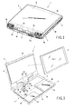
- FIG. 1 is a perspective view of a portable computer according to the first embodiment of the present invention;
- FIG. 2 is a perspective view of the portable computer according to the first embodiment, illustrating the positional relation of the heat-radiating portion and the display housing;
- FIG. 3 is a perspective view of the portable computer according to the first embodiment, schematically showing the first and second tubes that connect the pump and the heat-radiating portion;
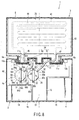
- FIG. 4 is a cross-sectional view of the portable computer according to the first embodiment, also showing the first and second tubes that connect the pump and the heat-radiating portion;
- FIG. 5 is a cross-sectional view, depicting the pump having a heat-receiving portion, which is supported by a support member and fixed on the printed circuit board;
- FIG. 6 is a plan view of the pump incorporated in the first embodiment of the present invention;
- FIG. 7 is a cross-sectional view of the heat-radiating portion provided in the first embodiment of the invention;
- FIG. 8 is a cross-sectional view of a portable computer according to the second embodiment of the present invention, illustrating the positional relation between the heat-receiving portion, pump, heat-radiating portion and circulation path;
- FIG. 9 is a cross-sectional view of the second embodiment, showing the heat-radiating portion that is supported by a support member and fixed on the printed circuit board; and
- FIG. 10 is a cross-sectional view of the second embodiment, depicting the pump that is supported by a support member and fixed on the printed circuit board.
- The first embodiment of this invention will be described, with reference to FIGS. 1 to 7.
- FIGS. 1 to 4 show a
portable computer 1, or an electronic apparatus according to this invention. Theportable computer 1 comprises a computermain unit 2 and adisplay unit 3. The computermain unit 2 has ahousing 4 that is shaped like a flat box. Thehousing 4 comprises abottom wall 4a, atop wall 4b, afront wall 4c, left andright sidewalls 4d, and a back wall 4e. Thetop wall 4b supports akeyboard 5. Thetop wall 4b has a pair ofprojections projections keyboard 5 and are spaced apart in the width direction of thehousing 4. - The
display unit 3 comprises adisplay housing 8 and a liquidcrystal display panel 9 incorporated in thedisplay housing 8. Thedisplay housing 8 is shaped like a flat box and has arectangular opening 10 in the front. The liquidcrystal display panel 9 has ascreen 9a that can display images. Thescreen 9a is exposed outside thehousing 8 through theopening 10. - The
display housing 8 has ahollow leg 11. As FIG. 4 shows, theleg 11 is continuous to the interior of thedisplay housing 8. Theleg 11 protrudes from the lower edge of thedisplay housing 8 and lies between theprojections housing 4. Theleg 11 has twoend portions first end portion 11a and thesecond end portion 11b lie adjacent to theprojections housing 4, respectively. - A pair of
hinges leg 11 to the rear edge of thehousing 4. Thefirst hinge 12a connects thefirst projection 6a of thehousing 4 and thefirst end portion 11a of theleg 11. Thesecond hinge 12b connects thesecond projection 6b of thehousing 4 and thesecond end portion 11b of theleg 11. Thus, thedisplay unit 3 is coupled to thehousing 4 and can be rotated between a closed position and an opened position. At the closed position, thedisplay unit 3 lies over thehousing 4, covering thekeyboard 5. At the opened position, thedisplay unit 3 stands up at the rear edge of thehousing 4, exposing thekeyboard 5 and the liquidcrystal display panel 9. - The
housing 4 contains a printedcircuit board 13, ahard disk drive 14, and a CD-ROM drive 15. Theboard 13,hard disk drive 14 and CD-ROM drive 15 are secured on thebottom wall 4a of thehousing 4. - As FIG. 5 shows, a
CPU 16 as a heat-generating component is mounted on the printedcircuit board 13. TheCPU 16 is, for example, a semiconductor package of the ball grid array (BGA) type. TheCPU 16 is located closer to the left side of thehousing 4 than to the middle part thereof. It has abase 17 and anIC chip 18 mounted on the center part of thebase 17. TheIC chip 18 generates much heat as it operates, processing data at high speeds and performing many functions. TheIC chip 18 needs to be cooled to keep operating in stable conditions. - As shown in FIGS. 3 and 4, the
portable computer 1 further comprises acooling unit 20 of the liquid-cooling type. The coolingunit 20 comprises a heat-receiving portion 21 (see FIG. 5), apump 22, a heat-radiatingportion 23, and acirculation path 24. - The heat-receiving
portion 21 is a metal plate larger than thebase 17 of theCPU 16 as illustrated in FIG. 5. It covers theIC chip 18 from above. Heat-conductive grease fills the gap between the heat-receivingportion 21 and theIC chip 18, thermally connecting theIC chip 18 to the lower surface of the heat-receivingportion 21. - The
pump 22 is formed integral with the heat-receivingportion 21. Thepump 22 comprises animpeller 25 and apump housing 26. Theimpeller 25 is connected to aflat motor 27, which is supported on thepump housing 26. The axis R1 of theimpeller 25 extends in the direction of thickness of thehousing 4. Theflat motor 27 starts rotating theimpeller 25 when the power switch to theportable computer 1 is closed (i.e., when the power is "on") or when the temperature of theCPU 16 rises to a preset value. - The
pump housing 26 is shaped like a flat box. It is made of heat-conductive metal such as aluminum alloy. It has abottom wall 28, atop wall 29, and eightsidewalls 30a to 30h. Thewalls pump chamber 31. Thepump chamber 31 contains theimpeller 25. - The
bottom wall 28 of thepump housing 26 is laid on the upper surface of the heat-receivingportion 21. Thebottom wall 28 is therefore thermally connected to the heat-receivingportion 21. The first toeighth sidewalls 30a to 30h are arranged, surrounding theimpeller 25 and connecting the edges of thebottom wall 28 to the edges of thetop wall 29. Thesidewalls 30a to 30h extend in lines tangential to the circumference of theimpeller 25. Thus, thepump housing 26 looks like a regular octagon as viewed from the axis R1 of theimpeller 25, as is illustrated in FIG. 6. - The
pump housing 26 has acoolant inlet port 32 and acoolant outlet port 33. Theports first sidewall 30a of thepump housing 26. They extend parallel to each other and are spaced apart from each other. - A
support member 35 fastens thepump 22 to the upper surface of the printedcircuit board 13. Thesupport member 35 is a leaf spring and can elastically deform. It opposes thetop wall 29 and extends in the diameter of thepump housing 26. - The
support member 35 has a pair oflegs projection 37. Thefirst leg 36a has been formed by bending one end portion of themember 35 downwards. Thesecond leg 36b has been formed by bending the other end portion of themember 35 downwards. Bothlegs projection 37 lies at the center of thesupport member 35 and protrudes downwards. -
Screws 39 fasten thelegs support member 35 to a pair of stud pins 38 that are secured to the printedcircuit board 13. Since thelegs board 13, the pushingprojection 37 abuts on thetop wall 29 of thepump housing 26. Theprojection 37 pushes the heat-receivingportion 21 onto theCPU 16. This is because theportion 21 is formed integral with thepump housing 26. As a result, both the heat-receivingportion 21. and thepump 22 are held on the printedcircuit board 13. - As FIG. 6 shows, the
first leg 36a of thesupport member 35 is interposed between thecoolant inlet port 32 andcoolant outlet port 33 of thepump 22. Thanks to this arrangement, thecoolant inlet port 32 or thecoolant outlet port 33 abuts on thefirst leg 36a of thesupport member 35 when thepump 22 moves in the circumferential direction of thepump housing 26. Thus, thesecond leg 36a serves as a stopper to restrict the motion of thepump 22. - As FIG. 4 depicts, the
pump 22 is offset leftwards from the axis O1 of depth of thehousing 4, or a line that passes the midpoint in the width of thehousing 4. Theaxis 01 goes across the center of theleg 11 of thedisplay housing 8, which is coupled to thehousing 4. - The
coolant inlet port 32 andcoolant outlet port 33 of thepump 22 extend backward and slantwise from thefirst sidewall 30a of thepump housing 26. Thus, they are directed toward the middle part of the junction between thedisplay housing 8 and thehousing 4. Theports housing 4. - As shown in FIGS. 3 and 4, the heat-radiating
portion 23 of the coolingunit 20 lies between the back of thedisplay housing 8 and the liquidcrystal display panel 9. The heat-radiatingportion 23 is a rectangular plate that has almost the same size as theliquid display panel 9. As FIG. 7 shows, the heat-radiatingportion 23 comprises two heat-radiatingplates plates - The first heat-radiating
plate 41 has arecess 43. Therecess 43 opens to the second heat-radiatingplate 42. It meanders, covering almost the entire first heat-radiatingplate 41. The second heat-radiatingplate 42 closes therecess 43. Hence, therecess 43 serves as acoolant path 44, which is defined by the first heat-radiatingplate 41 and the second heat-radiatingplate 42. - The heat-radiating
portion 23 has acoolant inlet port 46 and acoolant outlet port 47. Theports leg 11 of thedisplay housing 8. They are arranged symmetrical with respect to the axis O1 of depth of thehousing 4, located on the left and right sides of the axis O1, respectively. More specifically, thecoolant inlet port 46 is located at the left edge of the heat-radiatingportion 23 and is connected to the upstream end of thecoolant path 44. Thecoolant outlet port 47 is located at the right edge of the heat-radiatingportion 23 and is connected to the downstream end of thecoolant path 44. - As FIG. 4 illustrates, the
coolant inlet port 32 andcoolant outlet port 33 of thepump 22 protrude backwards from thefirst sidewall 30a of thepump housing 26 and incline to the axis O1. Therefore, theports coolant inlet port 46 andcoolant outlet port 47 of the heat-radiatingportion 23. - The
circulation path 24 that is provided in thecooling unit 20 comprises twopipes first pipe 50 connects thecoolant outlet port 33 of thepump 22 to thecoolant inlet port 46 of the heat-radiatingportion 23. Thefirst pipe 50 first extends in the direction thecoolant outlet port 33 protrudes, thus reaching the rear edge of thehousing 4, then passes ;through thefirst end portion 11a of theleg 11, and finally reaches the left side of thedisplay housing 8. - The
second pipe 51 of thecirculation path 24 connects thecoolant output port 47 of the heat-radiatingportion 23 to thecoolant inlet port 32 of thepump 22. Thepipe 51 first extends in the direction thecoolant inlet port 32 protrudes, thus reaching the rear edge of thehousing 4, then passes through thesecond end portion 11b of theleg 11, and finally reaches the right side of thedisplay housing 8. - Hence, the
first pipe 50 andsecond pipe 51 that constitute thecoolant path 24 extend from thepump 22, neither parallel to the axis O1 nor perpendicular thereto, as is clearly seen from FIG. 4. - The
first pipe 50 andsecond pipe 51 are tubes that are made of rubber or synthetic resin, either being flexible material. Made of flexible material, thepipes pump 22 and the heat-radiatingportion 23 move relative to each other as thedisplay unit 3 is rotated. Thus, thepipes circulation path 24 that occurs every time thedisplay unit 3 is rotated. - The
pump chamber 31 of thepump 22, thecoolant path 44 of the heat-radiatingportion 23, and thecirculation path 24 are filled with liquid coolant (or cooling medium). The liquid coolant is, for example, an antifreeze prepared by an ethylene glycol solution and, if necessary, a corrosion inhibitor, to water. - In the first embodiment described above, the
IC chip 18 of theCPU 16 generates heat while theportable computer 1 is being used. The heat that theIC chip 18 generates is transferred via the heat-receivingportion 21 to thebottom wall 28 of thepump housing 26. As indicated earlier, thepump chamber 31 of thepump housing 26 is filled with the liquid coolant. Therefore, the liquid coolant absorbs a greater part of the heat that has been transferred to thepump housing 26. - When the
impeller 25 of thepump 22 rotates, the liquid coolant is forced to the heat-radiatingportion 23 through thefirst pipe 50. The liquid coolant is made to circulate between thepump 31 and the heat-radiatingportion 23. More precisely, the liquid coolant heated in thepump chamber 31 is guided to the heat-radiatingportion 23 through thefirst pipe 50 and then flows through the meanderingcoolant path 44. While flowing through thecoolant path 44, the liquid coolant releases the heat. The heat diffuses in the first heat-radiatingplate 41 and second heat-radiatingplate 42. Theplates - Therefore, the liquid coolant is cooled as it passes through the
liquid path 44 and supplied back into thepump chamber 31 of thepump 22. This cooling cycle is repeated. As a result, the heat is transferred from theIC chip 18 to the heat-radiatingportion 23 provided in thedisplay housing 8 and is released from theportable computer 1 via the heat-radiatingportion 23. - In the
cooling unit 20, the first andsecond pipes pump 22, extend from thefirst side wall 30a of thepump housing 26, backwards and slantwise with respect to thepump 22. Thus, thepipes housing 4 and thedisplay housing 8. Therefore, they only need to run a shortest possible distance to be connected to thecoolant inlet port 46 and thecoolant outlet port 47, respectively, though thepump 22 is offset to the left from the axis O1 of depth of thehousing 4. Hence, thepipes - As a result, the evaporation of the liquid coolant from the
pipes pipes unit 20 need not be inspected so frequently to maintain it in good condition. - The more the evaporation of the liquid coolant is controlled, the more effectively the heat can be transferred from the
CPU 16 to the heat-radiatingportion 23, for a long period of time. The efficiency of cooling of theCPU 16 can therefore remain high for a long time. Thus, thecoolant unit 20 can cool theCPU 16 with high reliability. - The present invention is not limited to the first embodiment described above. FIGS. 8 to 10 illustrate the second embodiment of the invention.
- The second embodiment differs from the first embodiment in that a heat-receiving
portion 60 that receives the heat from theCPU 16 is spaced away from thepump 22. In any other respect, the second embodiment is identical to the first embodiment in terms of basic structure. The components similar or identical to those of the first embodiment are designated with the same reference numerals and will not be described again in detail. - As FIGS. 8 and 9 show, the heat-receiving
portion 60 has ahousing 61 that is shaped like a flat box. Thehousing 61 is made of heat-conductive metal such as aluminum alloy. It has abottom wall 62, atop wall 63, and eightsidewalls 64a to 64h. Thebottom wall 62 has a flat lower surface, which serves as a heat-receivingsurface 65. Heat-conductive grease (not shown) fills the gap between the heat-receivingsurface 65 and theIC chip 18 of theCPU 16, thermally connecting the heat-receivingportion 60 to theIC chip 18. The first to eightsidewalls 64a to 64h connect the edges of thebottom wall 62 to those of thetop wall 63. Thewalls coolant path 66 within thehousing 61. Coolant liquid can flow through thecoolant path 66. Thecoolant path 66 is thermally connected to theIC chip 18 by thebottom wall 62. - The first to
eighth sidewalls 64a to 64h are arranged, surrounding thecoolant path 66. Thus, thehousing 61 looks like a regular octagon as viewed from above. - The
housing 61 has acoolant inlet port 67 and acoolant outlet port 68. Thecoolant inlet port 67 is made in thesecond sidewall 64b and protrudes from the second side all 64b toward the left side of thehousing 4. Thecoolant outlet port 68 is made in thefirst sidewall 64a. Thisport 68 protrudes from thefirst sidewall 64a, backwards and slantwise toward a midpoint between thecoolant inlet port 46 andcoolant outlet port 47 of the heat-radiatingportion 23. - The
coolant outlet port 68 of the heat-receivingportion 60 is connected to thecoolant inlet port 46 of the heat-radiatingportion 23 by thefirst pipe 50 of thecirculation path 24. Thefirst pipe 50 first extends in the direction thecoolant outlet port 68 protrudes, thus reaching the rear edge of thehousing 4, then passes through thefirst end portion 11a of theleg 11, and finally reaches the left side of thedisplay housing 8. - As seen from FIG. 9, the
housing 61 of the heat-receivingportion 60 is secured on the upper surface of the printedcircuit board 13 by asupport member 70. Thesupport member 70 is a leaf spring and can elastically deform. It opposes thetop wall 63 of thehousing 61 and extends in the diameter of thehousing 61. - The
support member 70 has a pair oflegs part 72. Thefirst leg 71a has been formed by bending one end portion of themember 70 downwards. Thesecond leg 71b has been formed by bending the other end portion of themember 70 downwards. Bothlegs part 72 lies at the center of thesupport member 70 and protrudes downwards. -
Screws 74 fasten thelegs support member 70 to a pair of stud pins 73 that are secured to the printedcircuit board 13. Since thelegs board 13, the pushingpart 72 abuts on the center part of thetop wall 63 of thehousing 61. Thepart 72 pushes the heat-receivingsurface 65 of thehousing 61 onto theCPU 16. As a result, the heat-receivingportion 60 is held on the printedcircuit board 13, covering theCPU 16 from above. - As FIG. 8 depicts, the
pump 22 is offset leftwards from the axis O1 of depth of thehousing 4 and located adjacent to the heat-receivingportion 60. Thepump 22 and the heat-receivingportion 60 lie side by side. Thepump housing 26 of thepump 22 has a shape of a regular octagon as in the first embodiment. Thecoolant inlet port 32 of thepump 22 is made in thefirst sidewall 30a of thepump housing 26. It projects backward and slantwise from thefirst sidewall 30a of thepump housing 26. Thus, it extends toward a midpoint between thecoolant inlet port 46 andcoolant outlet port 47 of the heat-radiatingportion 23. Thecoolant inlet port 32 extends in the same direction as thecoolant outlet port 68 of the heat-receivingportion 60 does. - The
coolant inlet port 32 of thepump 22 is connected to thecoolant outlet port 47 of the heat-radiatingportion 23 by thesecond pipe 51 of thecirculation path 24. Thesecond pipe 51 first extends in the direction thecoolant inlet port 32 protrudes, thus reaching the rear edge of thehousing 4, then passes through thesecond end portion 11b of theleg 11, and finally reaches the right side of thedisplay housing 8. - The
coolant outlet port 33 of thepump 22 is made in thesixth sidewall 30f of thepump housing 26. Theport 33 extends from thesixth sidewall 30f toward the left side of thehousing 4. Arelay pipe 75 connects thecoolant outlet port 33 to thecoolant inlet port 67 of the heat-receivingportion 60. - As FIG. 10 shows, the
pump 22 is secured on the upper surface of the printedcircuit board 13 by asupport member 76, in a region outside theCPU 16. Thesupport member 76 is a leaf spring and can elastically deform. It opposes thetop wall 29 of thepump housing 26 and extends in the diameter of thepump housing 26. - The
support member 76 has a pair oflegs 77a and 77b and a pushingpart 78. Thefirst leg 77a has been formed by bending one end portion of themember 76 downwards. The second leg 77b has been formed by bending the other end portion of themember 76 downwards. Bothlegs 77a and 77b have an L-shaped cross section. The pushingpart 78 lies at the center of thesupport member 76 and protrudes downwards. -
Screws 80 fasten thelegs 77a and 77b of thesupport member 76 to a pair of stud pins 79 that are secured to the printedcircuit board 13. Since thelegs 77a and 77b are so fastened to theboard 13, the pushingpart 78 abuts on the center part of thetop wall 29 of thepump housing 26. Thepart 78 pushes thebottom wall 28 of thepump housing 26 onto the upper surface of the printedcircuit board 13. As a result, thepump 22 is held on the printedcircuit board 13. - In the second embodiment described above, the heat that the
IC chip 18 generates is transferred via the heat-receivingsurface 65 of thehousing 61. As mentioned earlier, thehousing 61 has thecoolant path 66 in which liquid coolant flows. The liquid coolant therefore absorbs a greater part of the heat that has been transferred to the heat-receivingsurface 65. - When the
impeller 25 of thepump 22 rotates, the liquid coolant is forced from thepump chamber 31 into thecoolant path 66 of the heat-receivingportion 60 via therelay pipe 75. The liquid coolant is made to flow through the meanderingcoolant path 44. While flowing through thecoolant path 44, the liquid coolant releases the heat generated by theIC chip 18. The heat diffuses in the first heat-radiatingplate 41 and second heat-radiatingplate 42. Theplates - Therefore, the liquid coolant is cooled as it passes through the
liquid path 44. The coolant thus cooled is supplied back into thepump chamber 31 of thepump 22 via thesecond pipe 51. The liquid coolant then flows through thecoolant path 66 of the heat-receivingportion 60 via therelay pipe 75. It absorbs the heat of theIC chip 18 again. This cooling cycle is repeated. As a result, the heat is transferred from theIC chip 18 to the heat-radiatingportion 23 provided in thedisplay housing 8 and is released from theportable computer 1 via the heat-radiatingportion 23. - In the second embodiment, the
first pipe 50, which is connected to thecoolant outlet port 68 of the heat-receivingportion 60, extends from thefirst side wall 64a of thehousing 61, backwards and slantwise with respect to the heat-receivingportion 60. Thus, thefirst pipe 50 is oriented toward the middle part of the junction between thehousing 4 and thedisplay housing 8. Similarly, thesecond pipe 51, which is connected to thecoolant inlet port 32 of thepump 22, extends from the firstwide wall 30a of thepump housing 26, backwards and slantwise, and is oriented toward the middle part of the junction between thehousing 4 and thedisplay housing 8. - Therefore, the
pipes coolant inlet port 46 and thecoolant outlet port 47, respectively, though thepump 22 is offset to the left from the axis O1 of depth of thehousing 4. Hence, bothpipes - This configuration can minimize the evaporation of the liquid coolant from the
pipes - In the second embodiment, the liquid coolant cooled in the heat-radiating portion is guided to the heat-receiving portion by a pump. Nonetheless, the present invention is not limited to this technical point. For example, the heat-receiving portion and the pump may be switched in position. In this case, the liquid coolant cooled in the heat-radiating portion is guided to the heat-receiving portion, heated in the heat-receiving portion and forced back into the heat-radiating portion by the pump.
- Moreover, the shapes of the pump housing and heat-receiving portion are not limited to an octagonal one. Instead, the pump housing and the heat-receiving portion may be, for example, square, pentagonal shape or circular.
- The pump may be offset from a midpoint in a width of the pump housing, or set along any suitable area within the electronic apparatus.
- Further, the electronic apparatuses according to this invention are not limited to portable computers. Rather, they may be data-processing apparatuses of any other types.
Claims (6)
- An electronic apparatus, comprising:a first housing (4) having a heat-generating component (16);a second housing (8) coupled to the first housing (4) ;a pump (22) incorporated into the first housing (4) having a heat-receiving portion (21) thermally connected to the heat-generating component (16) and offset toward one side of the first housing (4) from a midpoint in a width of the first housing (4);a heat-radiating portion (23) incorporated into the second housing (8) to radiate heat generated by the heat-generating component (16) and having a coolant inlet port (46) and a coolant outlet port (47); anda circulation path (24) to circulate a liquid coolant between the pump (22) and the heat-radiating portion (23),characterized in that the circulation path (24) having a first pipe (50) connecting the pump (22) to the coolant inlet port (46) of the heat-radiating portion (23) and a second pipe (51) connecting the pump (22) to the coolant outlet port (47) of the heat-radiating portion (23), the first pipe (50) and the second pipe (51) extending from two adjacent points on the pump (22), toward a midpoint between the coolant inlet port (46) and the coolant outlet port (47).
- The electronic apparatus according to claim 1, characterized in that the pump (22) has a coolant outlet port (33) and a coolant inlet port (32) to which the first pipe (50) and the second pipe (51) are connected, respectively, which are located adjacent to each other and protrude from the pump (22) toward the coolant inlet port (46) and coolant output port (47) of the heat-radiating portion (23), respectively.
- The electronic apparatus according to claim 2, characterized in that the coolant outlet port (33) and the coolant inlet port (32) of the pump (22) extend parallel to each other and are spaced apart from each other.
- The electronic apparatus according to claim 2 or 3, characterized in that the pump (22) has a polygonal pump housing (26) including a plurality of sidewalls (30a, 30b, 30c, 30d, 30e, 30f, 30g, 30h), and the coolant inlet port (32) and the coolant outlet port (33) of the pump (22) protrude from one sidewall (30a) of the pump housing (26) and extend parallel to each other.
- The electronic apparatus according to claim 2, characterized in that the pump (22) is secured to the first housing (4) by a support member (35), the support member (35) having a stopper (36a) interposed between the coolant outlet port (33) and the coolant inlet port (32) of the pump (22).
- The electronic apparatus according to claim 5, characterized in that the support member (35) resiliently pushes the heat-receiving portion (21) of the pump (22) onto the heat-generating component (16).
Applications Claiming Priority (2)
| Application Number | Priority Date | Filing Date | Title |
|---|---|---|---|
| JP2002300929A JP2004139187A (en) | 2002-10-15 | 2002-10-15 | Electronics |
| JP2002300929 | 2002-10-15 |
Publications (1)
| Publication Number | Publication Date |
|---|---|
| EP1413944A2 true EP1413944A2 (en) | 2004-04-28 |
Family
ID=32064253
Family Applications (1)
| Application Number | Title | Priority Date | Filing Date |
|---|---|---|---|
| EP03016725A Withdrawn EP1413944A2 (en) | 2002-10-15 | 2003-07-22 | Electronic apparatus with liquid cooling of a heat-generating component |
Country Status (4)
| Country | Link |
|---|---|
| US (1) | US6845011B2 (en) |
| EP (1) | EP1413944A2 (en) |
| JP (1) | JP2004139187A (en) |
| CN (1) | CN1490696A (en) |
Cited By (1)
| Publication number | Priority date | Publication date | Assignee | Title |
|---|---|---|---|---|
| EP1621970A3 (en) * | 2004-07-30 | 2007-02-21 | Kabushiki Kaisha Toshiba | Electronic apparatus with cooling device |
Families Citing this family (33)
| Publication number | Priority date | Publication date | Assignee | Title |
|---|---|---|---|---|
| JP2004139185A (en) * | 2002-10-15 | 2004-05-13 | Toshiba Corp | Electronics |
| KR100468783B1 (en) * | 2003-02-11 | 2005-01-29 | 삼성전자주식회사 | Clothespin typed apparatus for dissipating heat generated from semiconductor module |
| JP2004348650A (en) * | 2003-05-26 | 2004-12-09 | Toshiba Corp | Electronics |
| JP2005294519A (en) * | 2004-03-31 | 2005-10-20 | Toshiba Corp | Pump, cooling device, electrical equipment and personal computer |
| JP2005315157A (en) * | 2004-04-28 | 2005-11-10 | Toshiba Corp | Pump, cooling device and electronic equipment |
| JP2005315159A (en) * | 2004-04-28 | 2005-11-10 | Toshiba Corp | Pumps and electronic equipment |
| JP2005315156A (en) | 2004-04-28 | 2005-11-10 | Toshiba Corp | Pump and electronic device equipped with pump |
| JP2005315158A (en) * | 2004-04-28 | 2005-11-10 | Toshiba Corp | Pumps, cooling devices, and electronics |
| JP4377742B2 (en) * | 2004-04-30 | 2009-12-02 | 株式会社東芝 | Electronic device having a radiator, a cooling device, and a cooling device |
| US7458413B2 (en) * | 2004-11-12 | 2008-12-02 | International Business Machines Corporation | Semiconductor chip heat transfer device |
| JP2006261457A (en) * | 2005-03-17 | 2006-09-28 | Fujitsu Ltd | Heat receiving body, heat receiving apparatus and electronic device |
| JP2007095902A (en) * | 2005-09-28 | 2007-04-12 | Toshiba Corp | Cooling device and electronic device having cooling device |
| JP4843419B2 (en) * | 2005-10-13 | 2011-12-21 | ポリマテック株式会社 | Key sheet |
| US20070109746A1 (en) * | 2005-11-15 | 2007-05-17 | Klein David A | Liquid cooling of electronic system and method |
| US8240359B2 (en) * | 2006-04-17 | 2012-08-14 | Gerald Garrett | Liquid storage and cooling computer case |
| CN101802748B (en) | 2007-09-13 | 2014-07-16 | 富士通株式会社 | Liquid cooling unit and electronic device |
| US7791876B2 (en) * | 2008-05-12 | 2010-09-07 | Hewlett-Packard Development Company, L.P. | Hinge connector with liquid coolant path |
| JP5241414B2 (en) * | 2008-09-30 | 2013-07-17 | 三洋電機株式会社 | Image display device |
| JP5412815B2 (en) * | 2008-12-04 | 2014-02-12 | 富士通株式会社 | Cooling jacket, cooling unit, cooling system and electronic equipment |
| JP5445507B2 (en) * | 2010-06-03 | 2014-03-19 | 株式会社デンソー | Power converter |
| JP5609442B2 (en) * | 2010-09-02 | 2014-10-22 | 富士通株式会社 | Radiators and electronic devices |
| US8699216B2 (en) | 2010-10-22 | 2014-04-15 | Xplore Technologies Corp. | Computer with door-mounted electronics |
| US20140000854A1 (en) * | 2012-06-29 | 2014-01-02 | Fu-Jung Wu | Heat-dissipation base structure |
| KR20150111422A (en) * | 2014-03-21 | 2015-10-06 | 엘에스산전 주식회사 | Electronic component case for a vehicle |
| CN106304757B (en) * | 2015-05-27 | 2019-07-30 | 奇鋐科技股份有限公司 | Bendable water cooling device |
| US20160377356A1 (en) * | 2015-06-25 | 2016-12-29 | Asia Vital Components Co., Ltd. | Flexible and transformable water-cooling device |
| TWI602994B (en) * | 2016-01-27 | 2017-10-21 | 訊凱國際股份有限公司 | Heat exchange module and serial pump thereof |
| USD898021S1 (en) * | 2018-05-14 | 2020-10-06 | Compal Electronics, Inc. | Notebook computer with air tunnel cover |
| US11112839B2 (en) * | 2018-10-01 | 2021-09-07 | General Electric Company | Additively manufactured cooling assemblies for thermal and/or mechanical systems, and methods for manufacturing the assemblies |
| US10840167B2 (en) | 2018-11-19 | 2020-11-17 | Advanced Micro Devices, Inc. | Integrated heat spreader with configurable heat fins |
| CN110418549B (en) * | 2019-06-18 | 2021-01-29 | 华为技术有限公司 | A heat dissipation component, electronic equipment |
| US12100541B2 (en) * | 2020-09-14 | 2024-09-24 | Intel Corporation | Embedded cooling channel in magnetics |
| US12342508B2 (en) * | 2022-10-17 | 2025-06-24 | Google Llc | Continuous feed liquid coolant replacement |
Family Cites Families (17)
| Publication number | Priority date | Publication date | Assignee | Title |
|---|---|---|---|---|
| US5323847A (en) * | 1990-08-01 | 1994-06-28 | Hitachi, Ltd. | Electronic apparatus and method of cooling the same |
| JPH06266474A (en) * | 1993-03-17 | 1994-09-22 | Hitachi Ltd | Electronic apparatus equipment and lap top electronic apparatus equipment |
| JP3385482B2 (en) | 1993-11-15 | 2003-03-10 | 株式会社日立製作所 | Electronics |
| US5383340A (en) * | 1994-03-24 | 1995-01-24 | Aavid Laboratories, Inc. | Two-phase cooling system for laptop computers |
| US5606341A (en) * | 1995-10-02 | 1997-02-25 | Ncr Corporation | Passive CPU cooling and LCD heating for a laptop computer |
| US5731954A (en) * | 1996-08-22 | 1998-03-24 | Cheon; Kioan | Cooling system for computer |
| US5847925A (en) * | 1997-08-12 | 1998-12-08 | Compaq Computer Corporation | System and method for transferring heat between movable portions of a computer |
| US6250378B1 (en) * | 1998-05-29 | 2001-06-26 | Mitsubishi Denki Kabushiki Kaisha | Information processing apparatus and its heat spreading method |
| US6166907A (en) * | 1999-11-26 | 2000-12-26 | Chien; Chuan-Fu | CPU cooling system |
| JP3556578B2 (en) | 2000-06-29 | 2004-08-18 | 株式会社東芝 | Portable electronic device and cooling device used for this electronic device |
| JP2002099356A (en) | 2000-09-21 | 2002-04-05 | Toshiba Corp | Electronic equipment cooling device and electronic equipment |
| JP2002151638A (en) | 2000-11-08 | 2002-05-24 | Hitachi Ltd | Electronic equipment cooling device |
| JP3607608B2 (en) * | 2000-12-19 | 2005-01-05 | 株式会社日立製作所 | Liquid cooling system for notebook computers |
| JP2002188876A (en) * | 2000-12-20 | 2002-07-05 | Hitachi Ltd | Liquid cooling system and personal computer using the same |
| CA2352997A1 (en) * | 2001-07-13 | 2003-01-13 | Coolit Systems Inc. | Computer cooling apparatus |
| JP2003303034A (en) * | 2002-04-11 | 2003-10-24 | Toshiba Corp | Electronics |
| US6771498B2 (en) * | 2002-10-25 | 2004-08-03 | Thermal Corp. | Cooling system for hinged portable computing device |
-
2002
- 2002-10-15 JP JP2002300929A patent/JP2004139187A/en active Pending
-
2003
- 2003-07-22 EP EP03016725A patent/EP1413944A2/en not_active Withdrawn
- 2003-08-20 CN CNA03154827XA patent/CN1490696A/en active Pending
- 2003-08-29 US US10/651,788 patent/US6845011B2/en not_active Expired - Fee Related
Cited By (1)
| Publication number | Priority date | Publication date | Assignee | Title |
|---|---|---|---|---|
| EP1621970A3 (en) * | 2004-07-30 | 2007-02-21 | Kabushiki Kaisha Toshiba | Electronic apparatus with cooling device |
Also Published As
| Publication number | Publication date |
|---|---|
| US6845011B2 (en) | 2005-01-18 |
| US20040070940A1 (en) | 2004-04-15 |
| CN1490696A (en) | 2004-04-21 |
| JP2004139187A (en) | 2004-05-13 |
Similar Documents
| Publication | Publication Date | Title |
|---|---|---|
| US6845011B2 (en) | Electronic apparatus having a circulation path of liquid coolant to cool a heat-generating component | |
| US7273089B2 (en) | Electronic apparatus having a heat-radiating unit for radiating heat of heat-generating components | |
| US6833992B2 (en) | Electronic apparatus having a plurality of radiators in which liquid coolant flows | |
| US6900990B2 (en) | Electronic apparatus provided with liquid cooling type cooling unit cooling heat generating component | |
| US8289701B2 (en) | Liquid cooling unit and heat receiver therefor | |
| US7652884B2 (en) | Electronic apparatus including liquid cooling unit | |
| US7114551B2 (en) | Liquid cooling module | |
| KR100899368B1 (en) | Heat receiver for liquid cooling unit, liquid cooling unit and electronic apparatus | |
| US7672125B2 (en) | Electronic apparatus | |
| KR100902323B1 (en) | Electronic apparatus | |
| US20040070942A1 (en) | Electronic apparatus | |
| US6988537B2 (en) | Cooling unit having a plurality of heat-radiating fins, and electronic apparatus with the cooling unit | |
| KR100890971B1 (en) | Heat exchanger for liquid cooling unit, liquid cooling unit and electronic apparatus | |
| EP1411417A2 (en) | Electronic apparatus having a heat-radiating portion at the back of the display panel | |
| JP2004071882A (en) | Electronics | |
| US20040070935A1 (en) | Electronic apparatus having a liquid-coolant circulation path and an electric-signal cable | |
| JPH10107469A (en) | Heating component cooling device and electronic equipment |
Legal Events
| Date | Code | Title | Description |
|---|---|---|---|
| PUAI | Public reference made under article 153(3) epc to a published international application that has entered the european phase |
Free format text: ORIGINAL CODE: 0009012 |
|
| 17P | Request for examination filed |
Effective date: 20030722 |
|
| AK | Designated contracting states |
Kind code of ref document: A2 Designated state(s): AT BE BG CH CY CZ DE DK EE ES FI FR GB GR HU IE IT LI LU MC NL PT RO SE SI SK TR |
|
| AX | Request for extension of the european patent |
Extension state: AL LT LV MK |
|
| STAA | Information on the status of an ep patent application or granted ep patent |
Free format text: STATUS: THE APPLICATION HAS BEEN WITHDRAWN |
|
| 18W | Application withdrawn |
Effective date: 20041125 |