EP1413773A2 - Dispositif de contrôle proportionel électro-hydraulique à commande informatisée - Google Patents
Dispositif de contrôle proportionel électro-hydraulique à commande informatisée Download PDFInfo
- Publication number
- EP1413773A2 EP1413773A2 EP03017275A EP03017275A EP1413773A2 EP 1413773 A2 EP1413773 A2 EP 1413773A2 EP 03017275 A EP03017275 A EP 03017275A EP 03017275 A EP03017275 A EP 03017275A EP 1413773 A2 EP1413773 A2 EP 1413773A2
- Authority
- EP
- European Patent Office
- Prior art keywords
- control
- proportional
- pressure
- inlet
- control device
- Prior art date
- Legal status (The legal status is an assumption and is not a legal conclusion. Google has not performed a legal analysis and makes no representation as to the accuracy of the status listed.)
- Granted
Links
Images
Classifications
-
- F—MECHANICAL ENGINEERING; LIGHTING; HEATING; WEAPONS; BLASTING
- F15—FLUID-PRESSURE ACTUATORS; HYDRAULICS OR PNEUMATICS IN GENERAL
- F15B—SYSTEMS ACTING BY MEANS OF FLUIDS IN GENERAL; FLUID-PRESSURE ACTUATORS, e.g. SERVOMOTORS; DETAILS OF FLUID-PRESSURE SYSTEMS, NOT OTHERWISE PROVIDED FOR
- F15B11/00—Servomotor systems without provision for follow-up action; Circuits therefor
- F15B11/006—Hydraulic "Wheatstone bridge" circuits, i.e. with four nodes, P-A-T-B, and on-off or proportional valves in each link
-
- F—MECHANICAL ENGINEERING; LIGHTING; HEATING; WEAPONS; BLASTING
- F15—FLUID-PRESSURE ACTUATORS; HYDRAULICS OR PNEUMATICS IN GENERAL
- F15B—SYSTEMS ACTING BY MEANS OF FLUIDS IN GENERAL; FLUID-PRESSURE ACTUATORS, e.g. SERVOMOTORS; DETAILS OF FLUID-PRESSURE SYSTEMS, NOT OTHERWISE PROVIDED FOR
- F15B11/00—Servomotor systems without provision for follow-up action; Circuits therefor
- F15B11/003—Systems with load-holding valves
-
- F—MECHANICAL ENGINEERING; LIGHTING; HEATING; WEAPONS; BLASTING
- F15—FLUID-PRESSURE ACTUATORS; HYDRAULICS OR PNEUMATICS IN GENERAL
- F15B—SYSTEMS ACTING BY MEANS OF FLUIDS IN GENERAL; FLUID-PRESSURE ACTUATORS, e.g. SERVOMOTORS; DETAILS OF FLUID-PRESSURE SYSTEMS, NOT OTHERWISE PROVIDED FOR
- F15B11/00—Servomotor systems without provision for follow-up action; Circuits therefor
- F15B11/02—Systems essentially incorporating special features for controlling the speed or actuating force of an output member
- F15B11/04—Systems essentially incorporating special features for controlling the speed or actuating force of an output member for controlling the speed
- F15B11/042—Systems essentially incorporating special features for controlling the speed or actuating force of an output member for controlling the speed by means in the feed line, i.e. "meter in"
-
- F—MECHANICAL ENGINEERING; LIGHTING; HEATING; WEAPONS; BLASTING
- F15—FLUID-PRESSURE ACTUATORS; HYDRAULICS OR PNEUMATICS IN GENERAL
- F15B—SYSTEMS ACTING BY MEANS OF FLUIDS IN GENERAL; FLUID-PRESSURE ACTUATORS, e.g. SERVOMOTORS; DETAILS OF FLUID-PRESSURE SYSTEMS, NOT OTHERWISE PROVIDED FOR
- F15B11/00—Servomotor systems without provision for follow-up action; Circuits therefor
- F15B11/02—Systems essentially incorporating special features for controlling the speed or actuating force of an output member
- F15B11/04—Systems essentially incorporating special features for controlling the speed or actuating force of an output member for controlling the speed
- F15B11/044—Systems essentially incorporating special features for controlling the speed or actuating force of an output member for controlling the speed by means in the return line, i.e. "meter out"
Definitions
- the invention relates to a computerized electrohydraulic proportional control device of the type specified in the preamble of claim 1.
- Pressure sensors are included in the working lines. Furthermore, adjustment path sensors connected to the computer control are assigned to the main directional control valves. As a special feature, mechanical decoupling of the inlet and outlet control edges is provided, so that the inlet and outlet could each be controlled extremely sensitively and individually.
- the two proportional pilot valves each of which adjusts a main directional control valve, operate with the same pilot pressure, so that they influence one another and the mechanical decoupling of the control edges is at least partially nullified hydraulically.
- controlled braking of the discharge flow is necessary in particular if a pulling or pushing load acts on a mast section which cannot be controlled with sufficient certainty by a current regulator in the inlet, since the pulling one or pushing load temporarily reverses the kinematic relationships.
- a pulling or pushing load acts on a mast section which cannot be controlled with sufficient certainty by a current regulator in the inlet, since the pulling one or pushing load temporarily reverses the kinematic relationships.
- Such a situation can e.g. occur if a mast section touches an obstacle when lowering or an extreme mast position causes a reversal of the direction of force.
- the proportional pressure control valves In a control device known from US-B1-6 199 378, the proportional pressure control valves must each keep the working pressure or return pressure via slide pistons which are not leak-free in the shut-off positions. Therefore, the hydraulic consumer cannot be reliably blocked hydraulically.
- the proportional pressure control valves provided on the outlet side contain preloaded non-return valves that limit the maximum pressure and have priority over excessive pressure increases in the event of excessive pressure increases. This means that if the load in the hydraulic motor is reversed unintentionally, pressure medium can flow to the tank, although this is not controlled by the electronic control device. This leads to movements or changes in movement on the hydraulic motor, which cannot be controlled by the electronic control device. All proportional pressure regulating valves contain spools which are acted upon directly by the proportional solenoid without pressure pre-control. This requires large, expensive and strong proportional magnets, which makes it difficult to achieve sensitive control behavior.
- a control device known from US-A-5 875 701
- the moving components of an earth-moving machine are actuated via hydraulic consumers, which are controlled in direction and speed by means of a joystick control with a microprocessor and unspecified valve devices.
- the microprocessor is fed with information on the relative angular positions of the components of the machine and the joysticks.
- the invention has for its object to provide a control device of the type mentioned, especially for a mast that is leak-tight in all shut-off positions, and in which to take into account difficult load conditions that may have a reversing effect on the hydraulic motor, the inlet and the outlet can be controlled independently of one another and individually, the performance of modern computer controls being used to adjust the control device to changing load cases.
- the two proportional control seat valves offer the possibility of a floating position by setting the two drain proportional control seat valves to a selective passage position via the computer control. The information from the actual pressure sensors in the working lines of the hydraulic motor is processed via the computer control so that the appropriate setting is made for each control seat valve.
- the control is able to adapt to changes in the load conditions (e.g. changes between pulling and pushing load) and to maintain the set speed of the hydraulic motor despite a simple construction of the valve assembly.
- a pressure pilot control that can be activated against spring force via the proportional magnet in each control seat valve.
- an individual pilot pressure of the pressure control can be set, which cannot be influenced by the pilot pressure in another proportional control valve.
- the pressure pilot control performs the actual control adjustment of the control seat valve depending on the energization of the proportional solenoid, which therefore requires less primary force.
- the two inlet-side control seat valves and the two outlet-side control seat valves are in each case structurally identical, preferably even identical. If necessary, even all four control seat valves are identical to one another, preferably even identical. Both options also reduce the control effort (e.g. as control signals transmitting messages) for the computer control.
- the computer control operates with a CAN node in a CAN bus system to which the four proportional magnets are connected in parallel via a data bus.
- the data bus preferably has a daisy chain configuration for the four proportional magnets, for which fewer or no high-quality processors are required.
- a joint angle sensor in particular for angle detection for a superordinate mast tip position, should also be expediently provided and connected to the computer control.
- the adjustment of the respective Proportional control poppet valves via the computer control can then take place additionally or dominantly with regard to the mast tip position or the angle between mast sections.
- a pressure sensor for the inlet pressure to the inlet proportional control seat valves is also expediently connected to the computer control.
- the computer control then knows the pressure difference between the supply line and the working lines. With this information, the size of the valve passage (in the outlet and / or in the inlet) can be set even more precisely in order to achieve an ideal load-independent flow distribution (LUDV), i.e. a stepless and load-independent setting of the speed of the hydraulic motor, or just throttling precisely.
- LUDV load-independent flow distribution
- control routines of modern processors of a computer control can continue to be used profitably, even if an electric pump drive, and possibly a pressure sensor for the pump delivery pressure, are connected to a further CAN node of the bus system, so that the drive control or regulation of the pump via the Bus system is feasible.
- the pump can be a constant feed pump with an electrical bypass valve that is controlled from the bus system.
- the pump can be a pressure-constant control pump that can be switched electrically from the bus system to unpressurized.
- the pump can be a control pump with an electrical flow rate and / or delivery pressure setting controlled from the bus system.
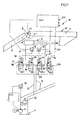
- a computerized, electro-hydraulic proportional control device S is used for speed and / or direction control of a hydraulic motor H, here an articulated cylinder of a mast M.
- the hydraulic motor H is arranged between two sections 1, 3 of the mast M.
- the two sections 1, 3 are at least pivotally connected to one another in a joint 2, so that an angle ⁇ between the sections 1, 3 can be adjusted by means of the hydraulic motor H.
- the hydraulic motor H is fed from a pump 4, which is driven by an electric drive M, for example.
- a pressure line 5 leads from the pump 4 to two 2/2-way proportional control seat valves VZ1, VZ2.
- the pressure line 5 may continue to other consumers or control devices, not shown.
- a return line 6 leads to a tank T, which comes from two outflow-side 2/2-way proportional control seat valves VA1, VA2.
- Two working lines 7, 8 each lead to the hydraulic motor H, each with a pressure sensor 9, 10 connected to a computer control CU (a converter which converts hydraulic pressure P into an electrical signal E).
- the pressure sensors 9, 10 are connected, for example, to a CAN node CK1 of a CAN bus system. If necessary, an angle sensor 11 is provided for the joint 2, which is also connected to the CAN node CK1 and serves to provide a higher mast tip position determined by angle detection.
- Another pressure sensor 11 is connected to the pressure line 5 and is electrically connected to a further CAN node CK2 of the bus system, wherein the electric pump drive M can also be connected to the CAN node CK2.
- the working line 7 branches off to the outlet-side proportional control valve VA1 and the inlet-side proportional control valve VZ1, with a branch in the branching branch to the inlet-side proportional control valve VZ1 in the direction of flow to the proportional control seat valve VZ1 non-leakage check valve 19 is arranged.
- a check valve 19 ' is also provided for the working line 8, which branches off to the proportional control seat valves VA2, VZ2.
- Each proportional control valve VA1, VA2, VZ1, VZ2 has its own proportional magnet 13, 14, 15, 16.
- the proportional magnets 13 to 16 are connected in parallel to a data bus 20 to the CAN node CK1. If necessary, the data bus 20 is designed as a daisy chain.
- a pressure pilot control 17 can be activated against the force of a valve spring 18, so that the proportional magnet adjusts the pilot pressure by adjusting the proportional control seat valve (servo effect).
- the proportional control seat valves are structurally separate from one another, the inlet and outlet control edges are also mechanically decoupled, and an individual pilot control pressure of the pressure pilot control 17 can also be set in each proportional control seat valve, which cannot be influenced by the pilot control pressure in another proportional control seat valve is.
- the proportional magnet 13 and the proportional magnet 16 are energized, possibly different from one another and as in the computer control Cu calculated or saved. If the angle ⁇ is to be reduced, the proportional magnet 14 and the proportional magnet 15 are energized. To brake an adjustment movement between the mast sections 1, 3, the current supply to the respective proportional magnet 15 or 16 is changed individually, for example in accordance with the information from the respective pressure sensor 9 or 10.
Landscapes
- Engineering & Computer Science (AREA)
- Physics & Mathematics (AREA)
- Fluid Mechanics (AREA)
- Mechanical Engineering (AREA)
- General Engineering & Computer Science (AREA)
- Fluid-Pressure Circuits (AREA)
Applications Claiming Priority (2)
| Application Number | Priority Date | Filing Date | Title |
|---|---|---|---|
| DE20215838U DE20215838U1 (de) | 2002-10-15 | 2002-10-15 | Computerisierte elektrohydraulische Proportional-Steuervorrichtung |
| DE20215838U | 2002-10-15 |
Publications (3)
| Publication Number | Publication Date |
|---|---|
| EP1413773A2 true EP1413773A2 (fr) | 2004-04-28 |
| EP1413773A3 EP1413773A3 (fr) | 2004-05-12 |
| EP1413773B1 EP1413773B1 (fr) | 2006-03-08 |
Family
ID=31969835
Family Applications (1)
| Application Number | Title | Priority Date | Filing Date |
|---|---|---|---|
| EP20030017275 Expired - Fee Related EP1413773B1 (fr) | 2002-10-15 | 2003-07-30 | Dispositif de contrôle proportionnel électro-hydraulique à commande informatisée |
Country Status (2)
| Country | Link |
|---|---|
| EP (1) | EP1413773B1 (fr) |
| DE (2) | DE20215838U1 (fr) |
Cited By (8)
| Publication number | Priority date | Publication date | Assignee | Title |
|---|---|---|---|---|
| EP1533520A1 (fr) * | 2003-11-18 | 2005-05-25 | HAWE Hydraulik GmbH & Co. KG | Système de réglage électrohydraulique régénérative de l'incidence des pales de turbine éolienne |
| WO2006094970A2 (fr) * | 2005-03-08 | 2006-09-14 | Robert Bosch Gmbh | Procede pour proteger contre les coincements, et dispositif anticoincement |
| WO2008000707A1 (fr) * | 2006-06-26 | 2008-01-03 | Robert Bosch Gmbh | Procédé pour actionner une capote de cabriolet électrohydraulique et système pour l'exécution de ce procédé |
| US7444809B2 (en) | 2006-01-30 | 2008-11-04 | Caterpillar Inc. | Hydraulic regeneration system |
| EP2199186A1 (fr) | 2008-12-17 | 2010-06-23 | HAWE Hydraulik SE | Dispositif de commande de direction hydraulique |
| EP2392819A1 (fr) * | 2010-05-31 | 2011-12-07 | HAWE Hydraulik SE | Dispositif de réglage rotatif hydroélectrique des pales de rotor sur le rotor d'une éolienne |
| CN102339026A (zh) * | 2011-05-26 | 2012-02-01 | 陈海波 | 一种基于重力调节的作业平台水平控制系统 |
| US8726645B2 (en) | 2010-12-15 | 2014-05-20 | Caterpillar Inc. | Hydraulic control system having energy recovery |
Families Citing this family (7)
| Publication number | Priority date | Publication date | Assignee | Title |
|---|---|---|---|---|
| DE102005010638A1 (de) * | 2005-03-08 | 2006-09-28 | Bosch Rexroth Aktiengesellschaft | Hydraulische Betätigungsvorrichtung, insbesondere für ein Cabriolet |
| DE102006012008A1 (de) * | 2006-03-14 | 2007-09-20 | Robert Bosch Gmbh | Steuervorrichtung zur Rotorblattverstellung |
| US7634911B2 (en) | 2007-06-29 | 2009-12-22 | Caterpillar Inc. | Energy recovery system |
| DE102009025827A1 (de) * | 2009-05-18 | 2010-11-25 | Bucyrus Dbt Europe Gmbh | Hydraulikschaltvorrichtung für die Mobilhydraulik, mobile Hydraulikmaschine und Ventileinheit |
| DE102012203390A1 (de) * | 2012-03-05 | 2013-09-05 | Robert Bosch Gmbh | Hydraulisches Antriebsystem mit gesonderten Zu- und Ablaufventilen und einer Regenerationsleitung |
| DE102012203387A1 (de) * | 2012-03-05 | 2013-09-05 | Robert Bosch Gmbh | Ventilbaugruppe mit Neutralumlauf und gesonderten Zu- und Ablaufventilen |
| AT514115B1 (de) | 2013-04-09 | 2015-05-15 | Ttcontrol Gmbh | Elektrohydraulischer Steuerkreis |
Citations (4)
| Publication number | Priority date | Publication date | Assignee | Title |
|---|---|---|---|---|
| US5875701A (en) | 1997-06-09 | 1999-03-02 | Caterpillar Inc. | Method and apparatus for controlling an implement of a work machine using linkage angles |
| EP0900888A1 (fr) | 1996-12-03 | 1999-03-10 | Shin Caterpillar Mitsubishi Ltd. | Dispositif de commande destine a un engin de construction |
| US6199378B1 (en) | 1999-09-21 | 2001-03-13 | Caterpillar Inc. | Off-setting rate of pressure rise in a fluid system |
| US6467264B1 (en) | 2001-05-02 | 2002-10-22 | Husco International, Inc. | Hydraulic circuit with a return line metering valve and method of operation |
Family Cites Families (1)
| Publication number | Priority date | Publication date | Assignee | Title |
|---|---|---|---|---|
| DE20114538U1 (de) * | 2001-09-03 | 2001-10-31 | Kuepper Weisser Gmbh | Hydrauliksystem für die Eigengewichtsentlastung von Anbaugeräten |
-
2002
- 2002-10-15 DE DE20215838U patent/DE20215838U1/de not_active Expired - Lifetime
-
2003
- 2003-07-30 DE DE50302571T patent/DE50302571D1/de not_active Expired - Lifetime
- 2003-07-30 EP EP20030017275 patent/EP1413773B1/fr not_active Expired - Fee Related
Patent Citations (4)
| Publication number | Priority date | Publication date | Assignee | Title |
|---|---|---|---|---|
| EP0900888A1 (fr) | 1996-12-03 | 1999-03-10 | Shin Caterpillar Mitsubishi Ltd. | Dispositif de commande destine a un engin de construction |
| US5875701A (en) | 1997-06-09 | 1999-03-02 | Caterpillar Inc. | Method and apparatus for controlling an implement of a work machine using linkage angles |
| US6199378B1 (en) | 1999-09-21 | 2001-03-13 | Caterpillar Inc. | Off-setting rate of pressure rise in a fluid system |
| US6467264B1 (en) | 2001-05-02 | 2002-10-22 | Husco International, Inc. | Hydraulic circuit with a return line metering valve and method of operation |
Non-Patent Citations (2)
| Title |
|---|
| "Klassiker kontra Neuentwicklung?", FLIUD, 1 January 2002 (2002-01-01) - 1 February 2002 (2002-02-01), pages 26 - 28,29 |
| Elektronic-Hydraulic CAN-Bus Control Systems" der Firma Ultronics Limited, GL 526 RT, Englang, mit der Registiernummer UL/1/1/500/CP/1/99 |
Cited By (10)
| Publication number | Priority date | Publication date | Assignee | Title |
|---|---|---|---|---|
| EP1533520A1 (fr) * | 2003-11-18 | 2005-05-25 | HAWE Hydraulik GmbH & Co. KG | Système de réglage électrohydraulique régénérative de l'incidence des pales de turbine éolienne |
| WO2006094970A2 (fr) * | 2005-03-08 | 2006-09-14 | Robert Bosch Gmbh | Procede pour proteger contre les coincements, et dispositif anticoincement |
| WO2006094970A3 (fr) * | 2005-03-08 | 2006-12-14 | Bosch Gmbh Robert | Procede pour proteger contre les coincements, et dispositif anticoincement |
| US7444809B2 (en) | 2006-01-30 | 2008-11-04 | Caterpillar Inc. | Hydraulic regeneration system |
| WO2008000707A1 (fr) * | 2006-06-26 | 2008-01-03 | Robert Bosch Gmbh | Procédé pour actionner une capote de cabriolet électrohydraulique et système pour l'exécution de ce procédé |
| EP2199186A1 (fr) | 2008-12-17 | 2010-06-23 | HAWE Hydraulik SE | Dispositif de commande de direction hydraulique |
| EP2392819A1 (fr) * | 2010-05-31 | 2011-12-07 | HAWE Hydraulik SE | Dispositif de réglage rotatif hydroélectrique des pales de rotor sur le rotor d'une éolienne |
| US8726645B2 (en) | 2010-12-15 | 2014-05-20 | Caterpillar Inc. | Hydraulic control system having energy recovery |
| CN102339026A (zh) * | 2011-05-26 | 2012-02-01 | 陈海波 | 一种基于重力调节的作业平台水平控制系统 |
| CN102339026B (zh) * | 2011-05-26 | 2014-05-28 | 昆山航天智能技术有限公司 | 一种基于重力调节的作业平台水平控制系统 |
Also Published As
| Publication number | Publication date |
|---|---|
| DE50302571D1 (de) | 2006-05-04 |
| EP1413773A3 (fr) | 2004-05-12 |
| EP1413773B1 (fr) | 2006-03-08 |
| DE20215838U1 (de) | 2004-02-26 |
Similar Documents
| Publication | Publication Date | Title |
|---|---|---|
| EP1588057B1 (fr) | Systeme hydraulique pour entrainements lineaires commandes par des elements deplaceurs | |
| DE69602923T3 (de) | Elektrohydraulische proportionale steuerventilvorrichtung | |
| EP1413773A2 (fr) | Dispositif de contrôle proportionel électro-hydraulique à commande informatisée | |
| EP0275968B1 (fr) | Dispositif de commande pour une transmission hydrostatique pour au moins deux utilisateurs | |
| DE102006003414B3 (de) | Hydraulische Schaltungsanordnung | |
| EP2628862B1 (fr) | Machine de travail mobile avec production d'énergie pour l'entraînement du refroidissement du moteur | |
| DE4100988C2 (de) | Hydraulisches Antriebssystem | |
| EP1635070B1 (fr) | Dispositif de contrôle électro-hydraulique | |
| DE10340504B4 (de) | Ventilanordnung zur Steuerung eines Hydraulikantriebs | |
| EP2136086B1 (fr) | Entraînement hydraulique | |
| DE19834955B4 (de) | Hydrostatisches Antriebssystem | |
| DE3729495C2 (fr) | ||
| DE102012203386A1 (de) | Steueranordnung | |
| DE102012007108A1 (de) | Valvistoranordnung | |
| DE10219717B3 (de) | Hydraulische Ventilanordnung | |
| EP1635072B1 (fr) | Dispositif de contrôle électro-hydraulique | |
| EP2171289A1 (fr) | Dispositif de commande pour au moins deux commandes hydrauliques | |
| DE10340505B4 (de) | Ventilanordnung zur Steuerung eines Hydraulikantriebs | |
| DE3901207C2 (de) | Ventilanordnung für mehrere hydraulische Antriebe, insbesondere für die Antriebe eines Krans | |
| DE102009047035A1 (de) | Steuerungssystem mit aufgelösten Steuerkanten | |
| EP2333351B1 (fr) | Module de levage hydroélectrique | |
| EP1831573B1 (fr) | Dispositif de commande hydraulique | |
| EP2062848B1 (fr) | Module de levage hydroélectrique | |
| EP2597209B1 (fr) | Système de réglage d'un dispositif de levage hydro-électronique | |
| DE102009054217B4 (de) | Hydraulikanordnung |
Legal Events
| Date | Code | Title | Description |
|---|---|---|---|
| PUAI | Public reference made under article 153(3) epc to a published international application that has entered the european phase |
Free format text: ORIGINAL CODE: 0009012 |
|
| PUAL | Search report despatched |
Free format text: ORIGINAL CODE: 0009013 |
|
| AK | Designated contracting states |
Kind code of ref document: A2 Designated state(s): AT BE BG CH CY CZ DE DK EE ES FI FR GB GR HU IE IT LI LU MC NL PT RO SE SI SK TR |
|
| AX | Request for extension of the european patent |
Extension state: AL LT LV MK |
|
| AK | Designated contracting states |
Kind code of ref document: A3 Designated state(s): AT BE BG CH CY CZ DE DK EE ES FI FR GB GR HU IE IT LI LU MC NL PT RO SE SI SK TR |
|
| AX | Request for extension of the european patent |
Extension state: AL LT LV MK |
|
| 17P | Request for examination filed |
Effective date: 20040707 |
|
| 17Q | First examination report despatched |
Effective date: 20040809 |
|
| AKX | Designation fees paid |
Designated state(s): DE FI FR IT SE |
|
| GRAP | Despatch of communication of intention to grant a patent |
Free format text: ORIGINAL CODE: EPIDOSNIGR1 |
|
| GRAS | Grant fee paid |
Free format text: ORIGINAL CODE: EPIDOSNIGR3 |
|
| GRAA | (expected) grant |
Free format text: ORIGINAL CODE: 0009210 |
|
| AK | Designated contracting states |
Kind code of ref document: B1 Designated state(s): DE FI FR IT SE |
|
| REF | Corresponds to: |
Ref document number: 50302571 Country of ref document: DE Date of ref document: 20060504 Kind code of ref document: P |
|
| REG | Reference to a national code |
Ref country code: SE Ref legal event code: TRGR |
|
| ET | Fr: translation filed | ||
| PLBE | No opposition filed within time limit |
Free format text: ORIGINAL CODE: 0009261 |
|
| STAA | Information on the status of an ep patent application or granted ep patent |
Free format text: STATUS: NO OPPOSITION FILED WITHIN TIME LIMIT |
|
| 26N | No opposition filed |
Effective date: 20061211 |
|
| PGFP | Annual fee paid to national office [announced via postgrant information from national office to epo] |
Ref country code: FI Payment date: 20070730 Year of fee payment: 5 |
|
| PGFP | Annual fee paid to national office [announced via postgrant information from national office to epo] |
Ref country code: IT Payment date: 20070723 Year of fee payment: 5 Ref country code: SE Payment date: 20070718 Year of fee payment: 5 |
|
| PGFP | Annual fee paid to national office [announced via postgrant information from national office to epo] |
Ref country code: FR Payment date: 20070718 Year of fee payment: 5 |
|
| EUG | Se: european patent has lapsed | ||
| REG | Reference to a national code |
Ref country code: FR Ref legal event code: ST Effective date: 20090331 |
|
| PG25 | Lapsed in a contracting state [announced via postgrant information from national office to epo] |
Ref country code: FI Free format text: LAPSE BECAUSE OF NON-PAYMENT OF DUE FEES Effective date: 20080730 |
|
| PG25 | Lapsed in a contracting state [announced via postgrant information from national office to epo] |
Ref country code: FR Free format text: LAPSE BECAUSE OF NON-PAYMENT OF DUE FEES Effective date: 20080731 Ref country code: IT Free format text: LAPSE BECAUSE OF NON-PAYMENT OF DUE FEES Effective date: 20080730 |
|
| PG25 | Lapsed in a contracting state [announced via postgrant information from national office to epo] |
Ref country code: SE Free format text: LAPSE BECAUSE OF NON-PAYMENT OF DUE FEES Effective date: 20080731 |
|
| PGFP | Annual fee paid to national office [announced via postgrant information from national office to epo] |
Ref country code: DE Payment date: 20100827 Year of fee payment: 8 |
|
| PG25 | Lapsed in a contracting state [announced via postgrant information from national office to epo] |
Ref country code: DE Free format text: LAPSE BECAUSE OF NON-PAYMENT OF DUE FEES Effective date: 20120201 |
|
| REG | Reference to a national code |
Ref country code: DE Ref legal event code: R119 Ref document number: 50302571 Country of ref document: DE Effective date: 20120201 |