EP1413754B1 - Closed compressor - Google Patents
Closed compressor Download PDFInfo
- Publication number
- EP1413754B1 EP1413754B1 EP02793344A EP02793344A EP1413754B1 EP 1413754 B1 EP1413754 B1 EP 1413754B1 EP 02793344 A EP02793344 A EP 02793344A EP 02793344 A EP02793344 A EP 02793344A EP 1413754 B1 EP1413754 B1 EP 1413754B1
- Authority
- EP
- European Patent Office
- Prior art keywords
- communication passage
- resonance frequency
- space
- hermetic compressor
- enclosed container
- Prior art date
- Legal status (The legal status is an assumption and is not a legal conclusion. Google has not performed a legal analysis and makes no representation as to the accuracy of the status listed.)
- Expired - Lifetime
Links
- 230000006835 compression Effects 0.000 claims description 37
- 238000007906 compression Methods 0.000 claims description 37
- 238000005461 lubrication Methods 0.000 claims description 2
- 239000003507 refrigerant Substances 0.000 description 31
- 230000010349 pulsation Effects 0.000 description 14
- 230000000694 effects Effects 0.000 description 3
- 238000004804 winding Methods 0.000 description 3
- XEEYBQQBJWHFJM-UHFFFAOYSA-N Iron Chemical compound [Fe] XEEYBQQBJWHFJM-UHFFFAOYSA-N 0.000 description 2
- 230000001902 propagating effect Effects 0.000 description 2
- 230000003321 amplification Effects 0.000 description 1
- 230000008602 contraction Effects 0.000 description 1
- 238000001816 cooling Methods 0.000 description 1
- 230000007423 decrease Effects 0.000 description 1
- 229910052742 iron Inorganic materials 0.000 description 1
- 239000000463 material Substances 0.000 description 1
- 238000003199 nucleic acid amplification method Methods 0.000 description 1
- 230000010355 oscillation Effects 0.000 description 1
- 229920003002 synthetic resin Polymers 0.000 description 1
- 239000000057 synthetic resin Substances 0.000 description 1
Images



Classifications
-
- F—MECHANICAL ENGINEERING; LIGHTING; HEATING; WEAPONS; BLASTING
- F04—POSITIVE - DISPLACEMENT MACHINES FOR LIQUIDS; PUMPS FOR LIQUIDS OR ELASTIC FLUIDS
- F04B—POSITIVE-DISPLACEMENT MACHINES FOR LIQUIDS; PUMPS
- F04B39/00—Component parts, details, or accessories, of pumps or pumping systems specially adapted for elastic fluids, not otherwise provided for in, or of interest apart from, groups F04B25/00 - F04B37/00
-
- F—MECHANICAL ENGINEERING; LIGHTING; HEATING; WEAPONS; BLASTING
- F04—POSITIVE - DISPLACEMENT MACHINES FOR LIQUIDS; PUMPS FOR LIQUIDS OR ELASTIC FLUIDS
- F04B—POSITIVE-DISPLACEMENT MACHINES FOR LIQUIDS; PUMPS
- F04B39/00—Component parts, details, or accessories, of pumps or pumping systems specially adapted for elastic fluids, not otherwise provided for in, or of interest apart from, groups F04B25/00 - F04B37/00
- F04B39/0027—Pulsation and noise damping means
- F04B39/0055—Pulsation and noise damping means with a special shape of fluid passage, e.g. bends, throttles, diameter changes, pipes
- F04B39/0061—Pulsation and noise damping means with a special shape of fluid passage, e.g. bends, throttles, diameter changes, pipes using muffler volumes
-
- Y—GENERAL TAGGING OF NEW TECHNOLOGICAL DEVELOPMENTS; GENERAL TAGGING OF CROSS-SECTIONAL TECHNOLOGIES SPANNING OVER SEVERAL SECTIONS OF THE IPC; TECHNICAL SUBJECTS COVERED BY FORMER USPC CROSS-REFERENCE ART COLLECTIONS [XRACs] AND DIGESTS
- Y10—TECHNICAL SUBJECTS COVERED BY FORMER USPC
- Y10S—TECHNICAL SUBJECTS COVERED BY FORMER USPC CROSS-REFERENCE ART COLLECTIONS [XRACs] AND DIGESTS
- Y10S181/00—Acoustics
- Y10S181/403—Refrigerator compresssor muffler
Definitions
- the present invention relates to a hermetic compressor for use in refrigerator, air-conditioner and refrigerating plant or the like.
- EPO 984162 A1 discloses an enclosed compressor and cooling system, wherein the compressor is provided with one or more small holes 17 formed in the shell of the section muffler formed with the lower thermal conductivity material such as synthetic resin.
- the small holes are positioned at nodes in a vibration mode for the resonance frequency formed in the hermetic shell so that amplification of the resonant sound in the space in the hermetic shell is suppressed.
- FIG. 5 shows a longitudinal sectional view of the conventional hermetic compressor.
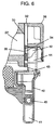
- FIG. 6 shows a partial sectional view of the conventional hermetic compressor.
- enclosed container 10 encloses motor element 50 consisting of stator 3A with winding 3a and rotor 4A, and compressor element 60 driven by motor element 50.
- Oil 80 is stored in the enclosed container 10.
- Crankshaft 10A has main axis 11 pressed to insert securely in rotor 4A and eccentric section 12 disposed in an eccentric position with respect to main axis 11.
- Oil pump 13 provided internal of main axis 11 of the crankshaft has an opening in oil 80.
- Cylinder block 20 having an approximately cylindrical shaped compression chamber 22 and bearing element 23 to hold main axis 11 is disposed above motor element 50.
- Piston 30 is reciprocably inserted into compression chamber 22 and is coupled to eccentric section 12 via coupler 31.
- Suction valve 35 comprises valve plate 32 to close an end face of compression chamber 22, movable valve 33 and suction hole 34 drilled in the valve plate to communicate with compression chamber 22.
- Head 36 forming a high-pressure chamber is fixed opposite to valve plate 32 of compression chamber 22.
- Suction pipe 39 fixed to enclosed container 10 is coupled to a low-pressure side (not shown) of the refrigerating cycle to draw the refrigerant gas (not shown) into enclosed container 10.
- Suction muffler 40 is fixed being held between muffling space 41, valve plate 32 and head 36.
- First end 42 of suction muffler 40 is communicated with suction hole 34 of valve plate 32.
- Second end 43 of suction muffler 40 has communication passage 44 terminating to open to muffling space 41, and opening 45 communicating with internal of muffling space 41 and internal of enclosed container 10 to open adjacent to suction pipe 39.
- the refrigerant gas flowed intermittently into compression chamber 22 via suction valve 35 through passage 44 and suction inlet opening 34 is compressed then discharged to the refrigerating system.
- open/shut movements of movable valve 33 generate pressure pulsations in the refrigerant gas and the pressure pulsations propagate opposite direction to the stream of the above refrigerant gas.
- the pressure pulsations of the refrigerant gas attenuates and muffles in repeated expansion and contraction during the path of refrigerant gas through communication passage 44, muffling space 41 and opening 45 in suction muffler 40 having respective different cross sectional areas.
- the problem is, therefore, that the noises do not attenuate sufficiently for some natural frequencies in the conventional art.
- the refrigerant gas sucked through opening 45 is discharged to muffling space 41 having a large space capacity before sent to communication passage 44.
- the refrigerant gas receives heat energy from inner surfaces of muffling space 41 resulting reduction of refrigerant gas density to cause a reduced refrigerating capacity.
- the resonance frequency of communication passage 44 that is determined by the length of communication passage 44 is difficult to adjust in the conventional art because communication passage 44 can not be extended any more. Consequently, pressure pulsations in communication passage 44 varied by the resonance frequency can not be maximized at the time just before the opening time of movable valve 33.
- the problem is that the volume of refrigerant gas flowing into compression chamber 22 decreases to cause a poor refrigerating capacity and efficiency.
- the present invention aims at to provide a hermetic compressor with a reduced noise emission in the muffling space of the suction muffler and an improved refrigerating capacity and efficiency to solve the aforementioned problems.
- the present invention aims at to provide a hermetic compressor comprising; a compression element; a motor element to drive rotatably the compression element; and a enclosed container that encloses the compression element and the motor element, and stores lubrication oil.
- the compression element includes; a cylinder block with a compression chamber; a valve plate forming a suction valve together with a movable valve to close an opening of the compression chamber of the cylinder block; a head forming a high-pressure chamber fixed to the cylinder block via the valve plate; and a suction muffler having a muffling space.
- the suction muffler includes; two rooms to be positioned with head being centered; a first communication passage, forming the muffling space together with the communication passage communicating the two rooms, to communicate the movable valve with the muffling space and to extend to an opening to the muffling space; and a second communication passage, communicating the enclosed container with the muffling space, to extend to an opening to the muffling space, wherein the openings in the muffling space from the first and the second communication passages are disposed in one of the two rooms, and the other room of the two rooms together with the communication space forms a resonance muffler whose resonance frequency matches with an cavity resonance frequency of the enclosed container.
- Enclosed container 101 contains motor element 105 consisted of stator 103A with winding 103a and rotor 104, and compressor element 106 driven by motor element 105 as shown in FIGS. 1 to 3.
- Oil 108 is stored in enclosed container 101.
- Crankshaft 110 has main axis 111 pressed to insert securely against rotor 104 and eccentric section 112 disposed in an eccentric position with respect to main axis 111.
- Oil pump 113 provided inside of main axis 111 of the crankshaft has an opening in oil 108.
- Cylinder block 120 having a substantially cylindrical shaped compression chamber 122 and bearing portion 123 to hold main axis 111 is disposed above motor element 105.
- Piston 130 is reciprocably inserted into compression chamber 122 and is coupled to eccentric portion 112 via conrod coupler131.
- Suction valve 135 comprises valve plate 132 to close an end face of compression chamber 122, resilient plate shaped movable valve 133 and suction hole 134 drilled in the valve plate to communicate with compression chamber 122.
- Head 136 forming a high-pressure chamber is fixed to cylinder block 120 via valve plate 132.
- Suction pipe 139 fixed to enclosed container 101 is coupled to a low-pressure side (not shown) of the refrigerating system to draw the refrigerant gas R134a (not shown) into enclosed container 101.
- enclosed container formed of iron plate by press working has a primary natural frequency of approximately 2.5 kHz.
- the cavity resonance frequency in enclosed container 101 is approx.
- Movable valve 133 has a primary natural frequency of approx. 250 Hz and a secondary natural frequency of approx. 500 Hz.
- Suction muffler 140 has muffling space 141 internally. Muffling space 141 is formed of two rooms (i.e., room A 140a and room B 140b) and communication space 140c to communicate with these rooms. Room A 140a and room B 140b are parted right and left with head 136 being centered.
- First communication passage 142 communicates movable valve 133 with muffling space 141.
- first communication passage 142 extends into muffling space 141 being inflected with an angle indicated by a of approximately 50 degree to dispose first opening 142a open to room B 140b in muffling space 141.
- Second communication passage 143 communicates enclosed container 101 internal with muffling space 141.
- Second opening 143a extends open to room B 140b in muffling space 141.
- the first opening and the second opening are located to open adjacently in room B 140b.
- Room A 140a together with communication space 140c forms a resonance muffler having a natural frequency of approx. 500 Hz.
- the resonance frequency is adjusted to approx. 750 Hz using the length of first communication passage 142 of approx. 70 mm.
- the frequency corresponds to triple of the primary natural frequency of movable valve 133 of 250 Hz.
- the frequency does not correspond to any one of the frequency group including; the cavity resonance frequency in enclosed container 101 of approx. 500Hz; the primary natural frequency of movable valve 133 of approx. 250 Hz; the secondary natural frequency of the same of approx. 500 Hz; and the natural frequency of enclosed container 101 of approx. 2.5 kHz.
- the resonance frequency is adjusted to approx. 1.2 kHz using the length of second communication passage 143 of 60 mm.
- the frequency does not correspond to any one of the frequency group including; the cavity resonance frequency of enclosed container 101 of approx. 500Hz; the primary natural frequency of movable valve 133 of approx. 250 Hz; the secondary natural frequency of the same of approx. 500 Hz; and the natural frequency of enclosed container 101 of approx. 2.5 kHz.
- both of first opening 142a of first communication passage 142 and second opening 143a of second communication passage 143 are located in room B 140b of muffling space 141.
- the places of the openings are allowed to correspond to a node of natural frequency of 2.5 kHz of enclosed container 101.
- the open/shut movement of movable valve 133 generates pressure pulsations of various frequencies.
- the pressure pulsations propagate opposite direction to stream of the aforementioned refrigerant gas.
- 500 Hz wave that is a natural frequency of cavity resonance acts as an oscillation source when the wave reaches into enclosed container 101.
- 1.2 kHz resonance frequency of second communication passage 143 do not meet the frequency of 2.5 kHz. Namely, 2.5 kHz band noises caused by pressure pulsation attenuate also in both of first communication passage 142 and second communication passage 143. The 2.5 kHz band noises are thus further suppressed to propagate into enclosed container 101..
- the configuration can prevent 2.5 kHz band noises from propagating from suction muffler 140 into enclosed container 101. Noises caused by resonance of 2.5 kHz band in enclosed container can be thus prevented.
- first communication passage 142 has the resonance frequency of approx. 750 Hz and second communication passage 143 has the resonance frequency of approx. 1.2 kHz respectively. Both of these frequencies do not meet any one of the primary natural frequency of movable valve 133 of approx. 250 Hz and the secondary natural frequency of approx. 500 Hz. Therefore, though having a large energy close to fundamental wave energy, the pressure pulsations generated by open/shut movements of movable valve 133 to suck refrigerant gas R134a to compression chamber attenuate in first communication passage 142 and second communication passage 143 resulting the pressure pulsations suppressed in a low level when released in enclosed container 101.
- movable valve 133 opens and shuts suction hole 134 in response to the reciprocating movements of piston 130.
- movable valve 133 performs a plurality times of open/shut movements per one reciprocating motion of piston 130 according to its own natural frequency.
- negative pressure waves are generated in the vicinity of suction hole 134.
- the negative pressure waves propagate along internal of first communication passage 142 and reflect at first opening 142a to return back soon in the vicinity of suction hole 134 being converted to positive pressure waves. Consequently, the pressure adjacent to movable valve 133 increases contrarily.
- integral multiple of the natural frequency of movable valve 133 is adopted for resonance frequency ratio determined by length and diameter of first communication passage 142. Then, open/shut timing of movable valve 133 is tuned in the pressure wave in first communication passage 142. Consequently, the pressure adjacent to movable valve 133 can be increased while movable valve 133 opens. Namely, supercharging effect can be expected.
- FIG. 4 shows a relation between resonance frequency of first communication passage 142 and efficiency increase due to the supercharging effect in a hermetic compressor used in the exemplary embodiment.
- a significant efficiency increase is observed when the ratio for the resonance frequency of first communication passage 142 to the natural frequency of movable valve 133 is an integral multiple of not larger than 4 as shown in the drawing.
- the resonance frequency of first communication passage 142 is set as triple number of 750 Hz against 250 Hz, the natural frequency of movable valve 133.
- first communication passage 142 is inflected with an angle of approx. 50 degrees.
- the structure can reduce the flow resistance of refrigerant gas.
- the angle is preferably be not smaller than 0 deg. and not larger than 60 deg., and the flow resistance runs up rapidly if the angle exceeds 75 degrees.
- first opening 142a of first communication passage 142 and second opening 143a of second communication passage 143 are terminated open adjacently each other in room B 140b.
- the structure contributes for refrigerant gas R134a sucked into room B 140b of suction muffler 140 from second communication passage 143 to be drawn into compression chamber 122 through first communication passage 142 via suction valve 134 with little heat received. Dense refrigerant gas, therefore, can be drawn into compression chamber 122 to provide a highly efficient compression performance.
- the present invention provides a hermetic compressor that can reduce noise emission caused by cavity resonance in the enclosed container and to have a highly efficient compression performance due to reduced heat influence on refrigerant gas.
Landscapes
- Engineering & Computer Science (AREA)
- Mechanical Engineering (AREA)
- General Engineering & Computer Science (AREA)
- Compressor (AREA)
- Applications Or Details Of Rotary Compressors (AREA)
Description
- The present invention relates to a hermetic compressor for use in refrigerator, air-conditioner and refrigerating plant or the like.
- Recently, a highly efficient and down sized hermetic compressor with reduced noise emission is required for refrigerating plant or the like.
- EPO 984162 A1 discloses an enclosed compressor and cooling system, wherein the compressor is provided with one or more small holes 17 formed in the shell of the section muffler formed with the lower thermal conductivity material such as synthetic resin. The small holes are positioned at nodes in a vibration mode for the resonance frequency formed in the hermetic shell so that amplification of the resonant sound in the space in the hermetic shell is suppressed.
- U.S. Patent No. 5,228,843 or Japanese Patent Laid-Open Application No. 2001-503833 discloses conventional arts of hermetic compressor.
- Now, a conventional hermetic compressor is described with reference to the drawings. FIG. 5 shows a longitudinal sectional view of the conventional hermetic compressor. FIG. 6 shows a partial sectional view of the conventional hermetic compressor. In FIGS. 5 and 6, enclosed
container 10 enclosesmotor element 50 consisting of stator 3A with winding 3a and rotor 4A, andcompressor element 60 driven bymotor element 50.Oil 80 is stored in the enclosedcontainer 10. Crankshaft 10A hasmain axis 11 pressed to insert securely in rotor 4A andeccentric section 12 disposed in an eccentric position with respect tomain axis 11.Oil pump 13 provided internal ofmain axis 11 of the crankshaft has an opening inoil 80.Cylinder block 20 having an approximately cylindricalshaped compression chamber 22 and bearingelement 23 to holdmain axis 11 is disposed abovemotor element 50. Piston 30 is reciprocably inserted intocompression chamber 22 and is coupled toeccentric section 12 viacoupler 31.Suction valve 35 comprisesvalve plate 32 to close an end face ofcompression chamber 22,movable valve 33 andsuction hole 34 drilled in the valve plate to communicate withcompression chamber 22.Head 36 forming a high-pressure chamber is fixed opposite tovalve plate 32 ofcompression chamber 22.Suction pipe 39 fixed to enclosedcontainer 10 is coupled to a low-pressure side (not shown) of the refrigerating cycle to draw the refrigerant gas (not shown) into enclosedcontainer 10.Suction muffler 40 is fixed being held betweenmuffling space 41,valve plate 32 andhead 36.First end 42 ofsuction muffler 40 is communicated withsuction hole 34 ofvalve plate 32.Second end 43 ofsuction muffler 40 hascommunication passage 44 terminating to open to mufflingspace 41, and opening 45 communicating with internal of mufflingspace 41 and internal of enclosedcontainer 10 to open adjacent tosuction pipe 39. - An operation of the hermetic compressor with aforementioned configuration is described. Rotor 4A of
motor element 50 rotatescrankshaft 10A, and the rotation movement ofeccentric section 12 travels topiston 30 viacoupler 31. Aspiston 30 reciprocates incompression chamber 22, refrigerant gas flows into enclosedcontainer 10 from the refrigerating system (not shown) throughsuction pipe 39. The flowed in refrigerant gas is sucked into mufflingspace 41 through opening 45 ofsuction muffler 40. - Next, the refrigerant gas flowed intermittently into
compression chamber 22 viasuction valve 35 throughpassage 44 andsuction inlet opening 34 is compressed then discharged to the refrigerating system. Here, at the time when the refrigerant gas is sucked intocompression chamber 22, open/shut movements ofmovable valve 33 generate pressure pulsations in the refrigerant gas and the pressure pulsations propagate opposite direction to the stream of the above refrigerant gas. The pressure pulsations of the refrigerant gas attenuates and muffles in repeated expansion and contraction during the path of refrigerant gas throughcommunication passage 44, mufflingspace 41 and opening 45 insuction muffler 40 having respective different cross sectional areas. - In the aforementioned conventional configuration, however, pressure pulsations generated in the refrigerant gas by open/shut movements of
movable valve 33 do not attenuate sufficiently. In addition, the pressure waves have large values at the passage opening 43 disposed at the end ofmuffling space 41. In mufflingspace 41, sound propagating compressional waves form standing waves for some natural frequencies by reflection. The sound pressure is high in dense portions (hereafter referred to as anti-node) of the standing waves and low in non-dense portions (hereafter referred to as node) of the standing waves. Among a distribution of the standing waves, the node is not produced at the end ofmuffling space 41. The problem is, therefore, that the noises do not attenuate sufficiently for some natural frequencies in the conventional art. Additionally, in the aforementioned conventional art, the refrigerant gas sucked throughopening 45 is discharged to mufflingspace 41 having a large space capacity before sent tocommunication passage 44. Here, the refrigerant gas receives heat energy from inner surfaces ofmuffling space 41 resulting reduction of refrigerant gas density to cause a reduced refrigerating capacity. - Moreover, the resonance frequency of
communication passage 44 that is determined by the length ofcommunication passage 44 is difficult to adjust in the conventional art becausecommunication passage 44 can not be extended any more. Consequently, pressure pulsations incommunication passage 44 varied by the resonance frequency can not be maximized at the time just before the opening time ofmovable valve 33. The problem is that the volume of refrigerant gas flowing intocompression chamber 22 decreases to cause a poor refrigerating capacity and efficiency. - The present invention aims at to provide a hermetic compressor with a reduced noise emission in the muffling space of the suction muffler and an improved refrigerating capacity and efficiency to solve the aforementioned problems.
- The present invention aims at to provide a hermetic compressor comprising; a compression element; a motor element to drive rotatably the compression element; and a enclosed container that encloses the compression element and the motor element, and stores lubrication oil.
- The compression element includes; a cylinder block with a compression chamber; a valve plate forming a suction valve together with a movable valve to close an opening of the compression chamber of the cylinder block; a head forming a high-pressure chamber fixed to the cylinder block via the valve plate; and a suction muffler having a muffling space.
- The suction muffler includes; two rooms to be positioned with head being centered; a first communication passage, forming the muffling space together with the communication passage communicating the two rooms, to communicate the movable valve with the muffling space and to extend to an opening to the muffling space; and a second communication passage, communicating the enclosed container with the muffling space, to extend to an opening to the muffling space, wherein the openings in the muffling space from the first and the second communication passages are disposed in one of the two rooms, and the other room of the two rooms together with the communication space forms a resonance muffler whose resonance frequency matches with an cavity resonance frequency of the enclosed container.
-
- FIG. 1 shows a longitudinal sectional view of the hermetic compressor used in the exemplary embodiment of the present invention.
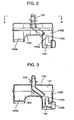
- FIG. 2 shows a front sectional view of the suction muffler used in the exemplary embodiment of the present invention.
- FIG. 3 shows a side sectional view taken along the line A - A' of the suction muffler used in the exemplary embodiment of the present invention.
- FIG. 4 a graph showing a relation between the resonance frequency of the first communication passage and the efficiency of the hermetic compressor used in the exemplary embodiment of the present invention.
- FIG. 5 shows a longitudinal sectional view of a conventional compressor.
- FIG. 6 shows a cross-sectional view of a suction muffler used in a conventional compressor.
- Now, an exemplary embodiment of the hermetic compressor disclosed in the present invention is described with reference to the drawings. The drawings are shown in schematic views and are not dimensioned correctly with regard to respective positioning.
- Enclosed
container 101 containsmotor element 105 consisted of stator 103A with winding 103a androtor 104, andcompressor element 106 driven bymotor element 105 as shown in FIGS. 1 to 3.Oil 108 is stored in enclosedcontainer 101.Crankshaft 110 hasmain axis 111 pressed to insert securely againstrotor 104 andeccentric section 112 disposed in an eccentric position with respect tomain axis 111.Oil pump 113 provided inside ofmain axis 111 of the crankshaft has an opening inoil 108.Cylinder block 120 having a substantially cylindrical shaped compression chamber 122 and bearingportion 123 to holdmain axis 111 is disposed abovemotor element 105. Piston 130 is reciprocably inserted into compression chamber 122 and is coupled toeccentric portion 112 via conrod coupler131.Suction valve 135 comprises valve plate 132 to close an end face of compression chamber 122, resilient plate shapedmovable valve 133 andsuction hole 134 drilled in the valve plate to communicate with compression chamber 122.Head 136 forming a high-pressure chamber is fixed tocylinder block 120 via valve plate 132.Suction pipe 139 fixed to enclosedcontainer 101 is coupled to a low-pressure side (not shown) of the refrigerating system to draw the refrigerant gas R134a (not shown) into enclosedcontainer 101. Here, enclosed container formed of iron plate by press working has a primary natural frequency of approximately 2.5 kHz. In addition, the cavity resonance frequency inenclosed container 101 is approx. 500 Hz with the use of refrigerant gas R134a.Movable valve 133 has a primary natural frequency of approx. 250 Hz and a secondary natural frequency of approx. 500 Hz.Suction muffler 140 has mufflingspace 141 internally.Muffling space 141 is formed of two rooms (i.e.,room A 140a androom B 140b) andcommunication space 140c to communicate with these rooms.Room A 140a androom B 140b are parted right and left withhead 136 being centered.First communication passage 142 communicatesmovable valve 133 with mufflingspace 141. Additionally,first communication passage 142 extends into mufflingspace 141 being inflected with an angle indicated by a of approximately 50 degree to disposefirst opening 142a open toroom B 140b in mufflingspace 141.Second communication passage 143 communicates enclosedcontainer 101 internal with mufflingspace 141.Second opening 143a extends open toroom B 140b in mufflingspace 141. The first opening and the second opening are located to open adjacently inroom B 140b.Room A 140a together withcommunication space 140c forms a resonance muffler having a natural frequency of approx. 500 Hz. - The resonance frequency is adjusted to approx. 750 Hz using the length of
first communication passage 142 of approx. 70 mm. The frequency corresponds to triple of the primary natural frequency ofmovable valve 133 of 250 Hz. - On the other hand, the frequency does not correspond to any one of the frequency group including; the cavity resonance frequency in
enclosed container 101 of approx. 500Hz; the primary natural frequency ofmovable valve 133 of approx. 250 Hz; the secondary natural frequency of the same of approx. 500 Hz; and the natural frequency ofenclosed container 101 of approx. 2.5 kHz. - The resonance frequency is adjusted to approx. 1.2 kHz using the length of
second communication passage 143 of 60 mm. The frequency does not correspond to any one of the frequency group including; the cavity resonance frequency ofenclosed container 101 of approx. 500Hz; the primary natural frequency ofmovable valve 133 of approx. 250 Hz; the secondary natural frequency of the same of approx. 500 Hz; and the natural frequency ofenclosed container 101 of approx. 2.5 kHz. - Moreover, both of
first opening 142a offirst communication passage 142 andsecond opening 143a ofsecond communication passage 143 are located inroom B 140b of mufflingspace 141. The places of the openings are allowed to correspond to a node of natural frequency of 2.5 kHz ofenclosed container 101. - Next, an operation of the hermetic compressor with aforementioned configuration is described.
Rotor 104 ofmotor element 105 rotatescrankshaft 110 accompanying the rotary movement ofeccentric section 112 that is conducted topiston 130 viacoupler 131. Aspiston 130 reciprocates in compression chamber 122, refrigerant gas R134a flows intoenclosed container 101 from the refrigerating system (not shown). The refrigerant gas first flows intoenclosed container 101 throughsuction pipe 139. Then, the refrigerant gas is released toroom B 140b viasecond communication passage 143 ofsuction muffler 140. Next, traveling throughsuction hole 134 viafirst communication passage 142, the refrigerant gas flows into compression chamber 122, whenmovable valve 133 is opened, and is compressed then discharged to the refrigerating system.Movable valve 133 opens and shuts when refrigerant gas R134a is sucked into compression chamber 122. - The open/shut movement of
movable valve 133 generates pressure pulsations of various frequencies. The pressure pulsations propagate opposite direction to stream of the aforementioned refrigerant gas. Among the pressure pulsations, 500 Hz wave that is a natural frequency of cavity resonance acts as an oscillation source when the wave reaches intoenclosed container 101. - Consequently, 500 Hz band noises, corresponding to the natural frequency of cavity resonance of
enclosed container 101, increase inenclosed container 101. However, 500 Hz band noises in the pressure pulsations attenuate greatly inroom B 140b because resonance muffler having the resonance frequency of approx. 500 Hz is produced byroom A 140a together withcommunication space 140c. Additionally, both of the resonance frequency offirst communication passage 142 of approx. 750 Hz and the resonance frequency ofsecond communication passage 143 of approx. 1.2 kHz do not meet the frequency of 500 Hz. Attenuating also in bothfirst communication passage 142 andsecond communication passage 143, the 500 Hz band noises generated by the pressure pulsations are further hard to propagate intoenclosed container 101. As mentioned above, the oscillating power caused by the cavity resonance inenclosed container 101 is reduced with the use of refrigerant gas R134a. Consequently, 500 Hz band noises caused by the cavity resonance inenclosed container 101 can be suppressed in a low level. - Additionally, among pulsation components generated by open/shut movements of
movable valve 133, 2.5 kHz band noises induce a resonance with a natural frequency ofenclosed container 101 when released into the space ofenclosed container 101. Then, the sound phenomenon occurs in enclosed container. On the other hand, both offirst opening 142a offirst communication passage 142 andsecond opening 143a ofsecond communication passage 143 are terminated open to positions corresponding to the nodes of vibration mode of 2.5 kHz band noises in mufflingspace 141. Consequently, 2.5 kHz band noises generated by open/shut movements ofmovable valve 133 attenuate greatly in the muffling space. In addition to this, both of approx. 750 Hz resonance frequency offirst communication passage 142 and approx. 1.2 kHz resonance frequency ofsecond communication passage 143 do not meet the frequency of 2.5 kHz. Namely, 2.5 kHz band noises caused by pressure pulsation attenuate also in both offirst communication passage 142 andsecond communication passage 143. The 2.5 kHz band noises are thus further suppressed to propagate intoenclosed container 101.. The configuration can prevent 2.5 kHz band noises from propagating fromsuction muffler 140 intoenclosed container 101. Noises caused by resonance of 2.5 kHz band in enclosed container can be thus prevented. - Additionally,
first communication passage 142 has the resonance frequency of approx. 750 Hz andsecond communication passage 143 has the resonance frequency of approx. 1.2 kHz respectively. Both of these frequencies do not meet any one of the primary natural frequency ofmovable valve 133 of approx. 250 Hz and the secondary natural frequency of approx. 500 Hz. Therefore, though having a large energy close to fundamental wave energy, the pressure pulsations generated by open/shut movements ofmovable valve 133 to suck refrigerant gas R134a to compression chamber attenuate infirst communication passage 142 andsecond communication passage 143 resulting the pressure pulsations suppressed in a low level when released inenclosed container 101. - On the other hand, upon operation of the compressor,
movable valve 133 opens and shutssuction hole 134 in response to the reciprocating movements ofpiston 130. In this regard,movable valve 133 performs a plurality times of open/shut movements per one reciprocating motion ofpiston 130 according to its own natural frequency. At the instant whenmovable valve 133 opens to suck the refrigerant gas into compression chamber 122, negative pressure waves are generated in the vicinity ofsuction hole 134. The negative pressure waves propagate along internal offirst communication passage 142 and reflect atfirst opening 142a to return back soon in the vicinity ofsuction hole 134 being converted to positive pressure waves. Consequently, the pressure adjacent tomovable valve 133 increases contrarily. - Therefore, integral multiple of the natural frequency of
movable valve 133 is adopted for resonance frequency ratio determined by length and diameter offirst communication passage 142. Then, open/shut timing ofmovable valve 133 is tuned in the pressure wave infirst communication passage 142. Consequently, the pressure adjacent tomovable valve 133 can be increased whilemovable valve 133 opens. Namely, supercharging effect can be expected. - FIG. 4 shows a relation between resonance frequency of
first communication passage 142 and efficiency increase due to the supercharging effect in a hermetic compressor used in the exemplary embodiment. A significant efficiency increase is observed when the ratio for the resonance frequency offirst communication passage 142 to the natural frequency ofmovable valve 133 is an integral multiple of not larger than 4 as shown in the drawing. In the exemplary embodiment, the resonance frequency offirst communication passage 142 is set as triple number of 750 Hz against 250 Hz, the natural frequency ofmovable valve 133. - Consequently, efficiency of the hermetic compressor increases because refrigerant gas volume sucked into compression chamber 122 increases to improve the suction efficiency due to the aforementioned supercharging effect. In addition,
first communication passage 142 is inflected with an angle of approx. 50 degrees. The structure can reduce the flow resistance of refrigerant gas. The angle is preferably be not smaller than 0 deg. and not larger than 60 deg., and the flow resistance runs up rapidly if the angle exceeds 75 degrees. - Moreover,
first opening 142a offirst communication passage 142 andsecond opening 143a ofsecond communication passage 143 are terminated open adjacently each other inroom B 140b. The structure contributes for refrigerant gas R134a sucked intoroom B 140b ofsuction muffler 140 fromsecond communication passage 143 to be drawn into compression chamber 122 throughfirst communication passage 142 viasuction valve 134 with little heat received. Dense refrigerant gas, therefore, can be drawn into compression chamber 122 to provide a highly efficient compression performance. - Needless to say, other refrigerant gas than R134a adopted in the description can perform the same purpose of this invention.
- The present invention provides a hermetic compressor that can reduce noise emission caused by cavity resonance in the enclosed container and to have a highly efficient compression performance due to reduced heat influence on refrigerant gas.
-
- α,
- Angle of bend
- 10, 101
- Enclosed container
- 10A, 110
- Crankshaft
- 13, 113
- Oil pump
- 20, 120
- Cylinder block
- 22, 122
- Compression chamber
- 3A, 103A
- Stator
- 3a, 103a
- Winding
- 30, 130
- Piston
- 32, 132
- Valve plate
- 33, 133
- Movable valve
- 35, 135
- Suction valve
- 36, 136
- Head
- 4A, 104
- Rotor
- 40, 140
- Suction muffler
- 41, 141
- Muffling space
- 50, 105
- Motor element
- 60, 106
- Compression element
- 80, 108
- Oil
- 140a
- Room A
- 140b
- Room B
- 140c
- communication space
- 142
- First communication passage
- 142a
- First opening
- 143
- Second communication passage
- 143a
- Second opening
Claims (7)
- A hermetic compressor comprising;(a) a compression element (106);(b) a motor element (105) to drive rotatably said compression element (106); and(c) an enclosed container (101) that encloses said compression element (106) and said motor element(105), and stores lubrication oil (108), whereinsaid compression element including:(d) a cylinder block (120) including a compression chamber (122);(e) a valve plate (132) forming a suction valve (135) together with a movable valve (133) to close an opening of said compression chamber (122) of said cylinder block (120);(f) a head (136) forming a high-pressure chamber fixed to said cylinder block (120) via said valve plate (132); and(g) a suction muffler(140) including a muffling space (141),characterized in that
said suction muffler(140) includes:(h) said muffling space (141) formed of two rooms (140a, 140b) and a communication space (140c) communicating said two rooms (140a, 140b);(i) a first communication passage (142) communicating said movable valve (133) with said muffling space (141) and extending to form an opening (142a) to said muffling space (141); and(j) a second communications passage (143), communicating said endorsed container (101) with said muffling space (141), extending to form an opening (143a) to said muffling space (141), whereinsaid openings (142a, 143a) in said muffling space (141) from said first and said second communication passages (142, 143) are disposed in one of said two rooms (140a, 140b), and the other room of said two rooms (140a, 140b) together with said communication space (140c) forms a resonance muffler having a resonance frequency matching with a cavity resonance frequency of said enclosed container (101). - The hermetic compressor according to claim 1, wherein an opening of one of said first communication passage (142) and said second communication passage (143) in said muffling space (141) is provided at a position corresponding to a mode of natural frequency of said muffling space (141).
- The hermetic compressor according to one of claims 1 and 2, wherein said first communication passage (142) has a resonance frequency of an integral multiple of not larger than 4 of a natural frequency of said moveable valve (133).
- The hermetic compressor according to one of claims 1 to 3, wherein said first communication passage (142) is inflected with an angle of not larger than 60 degrees.
- The hermetic compressor according to one of claims 1 to 3, wherein said first communication passage (142) and said second communication passage (143) have a resonance frequency different from a cavity resonance frequency in said enclosed container (101) respectfully.
- The hermetic compressor according to one of claims 1 to 3, wherein said first communication passage (142) and said second communication passage (143) have a resonance frequency different from a primary and a secondary resonance frequency of said moveable valve (133) respectively.
- The hermetic compressor according to one of claims 1 to 3, wherein said first communication passage (142) and said second communication passage (143) having a resonance frequency different from a natural frequency of said enclosed container (101) respectively.
Applications Claiming Priority (3)
| Application Number | Priority Date | Filing Date | Title |
|---|---|---|---|
| JP2001371248 | 2001-12-05 | ||
| JP2001371248A JP4101505B2 (en) | 2001-12-05 | 2001-12-05 | Hermetic compressor |
| PCT/JP2002/012637 WO2003048574A1 (en) | 2001-12-05 | 2002-12-03 | Closed compressor |
Publications (3)
| Publication Number | Publication Date |
|---|---|
| EP1413754A1 EP1413754A1 (en) | 2004-04-28 |
| EP1413754A4 EP1413754A4 (en) | 2005-11-16 |
| EP1413754B1 true EP1413754B1 (en) | 2006-08-23 |
Family
ID=19180321
Family Applications (1)
| Application Number | Title | Priority Date | Filing Date |
|---|---|---|---|
| EP02793344A Expired - Lifetime EP1413754B1 (en) | 2001-12-05 | 2002-12-03 | Closed compressor |
Country Status (8)
| Country | Link |
|---|---|
| US (1) | US7052248B2 (en) |
| EP (1) | EP1413754B1 (en) |
| JP (1) | JP4101505B2 (en) |
| KR (1) | KR100538855B1 (en) |
| CN (2) | CN1312400C (en) |
| AU (1) | AU2002359970A1 (en) |
| DE (1) | DE60214196T2 (en) |
| WO (1) | WO2003048574A1 (en) |
Families Citing this family (16)
| Publication number | Priority date | Publication date | Assignee | Title |
|---|---|---|---|---|
| JP4101505B2 (en) * | 2001-12-05 | 2008-06-18 | 松下冷機株式会社 | Hermetic compressor |
| KR100618223B1 (en) * | 2003-08-18 | 2006-09-01 | 엘지전자 주식회사 | Suction silencer of hermetic compressor |
| JP4576944B2 (en) * | 2004-09-13 | 2010-11-10 | パナソニック株式会社 | Refrigerant compressor |
| JP4682596B2 (en) * | 2004-11-24 | 2011-05-11 | パナソニック株式会社 | Hermetic compressor |
| AT8401U1 (en) * | 2005-03-31 | 2006-07-15 | Acc Austria Gmbh | REFRIGERANT COMPRESSOR |
| JP4670529B2 (en) * | 2005-07-29 | 2011-04-13 | ダイキン工業株式会社 | Compressor |
| KR100774483B1 (en) * | 2006-01-05 | 2007-11-08 | 엘지전자 주식회사 | Compressor suction muffler structure |
| AT9232U1 (en) * | 2006-05-22 | 2007-06-15 | Acc Austria Gmbh | REFRIGERANT COMPRESSOR |
| KR100830235B1 (en) | 2007-01-09 | 2008-05-16 | 엘지전자 주식회사 | Suction Muffler of Hermetic Compressor |
| JP4396753B2 (en) * | 2007-10-03 | 2010-01-13 | 株式会社デンソー | Silencer for refrigeration cycle |
| US8222048B2 (en) | 2007-11-05 | 2012-07-17 | Abbott Laboratories | Automated analyzer for clinical laboratory |
| US8235683B2 (en) * | 2007-12-06 | 2012-08-07 | Panasonic Corporation | Hermetic compressor |
| KR101457699B1 (en) * | 2008-06-02 | 2014-11-04 | 엘지전자 주식회사 | Suction muffler of hermetic compressor |
| ITCO20110070A1 (en) * | 2011-12-20 | 2013-06-21 | Nuovo Pignone Spa | METHODS AND DEVICES FOR CONSTRUCTIVE USE OF PRESSURE PULSES IN INSTALLATIONS OF ALTERNATIVE COMPRESSORS |
| BR102016013787B1 (en) * | 2016-06-14 | 2022-05-17 | Embraco Indústria De Compressores E Soluções Em Refrigeração Ltda | Acoustic filter for compressor |
| JP6760148B2 (en) * | 2017-03-10 | 2020-09-23 | 株式会社豊田自動織機 | Electric compressor for vehicles |
Family Cites Families (13)
| Publication number | Priority date | Publication date | Assignee | Title |
|---|---|---|---|---|
| RO100617B1 (en) * | 1989-10-06 | 1993-02-28 | îNTREPRINDEREA DE FRIGIDERE | Compressor for household refrigerators |
| US5496156A (en) * | 1994-09-22 | 1996-03-05 | Tecumseh Products Company | Suction muffler |
| KR0136612Y1 (en) * | 1995-08-17 | 1999-03-20 | 구자홍 | Suction silencer of hermetic electric compressor |
| EP1304481B8 (en) * | 1996-01-23 | 2006-03-08 | Matsushita Refrigeration Company | Compressor discharge muffler |
| IT241575Y1 (en) * | 1996-11-19 | 2001-05-09 | Zanussi Elettromecc | REFRIGERATED COMPRESSOR WITH HEAD AND SILENCER PERFECTED |
| JP3725294B2 (en) * | 1997-05-21 | 2005-12-07 | 松下冷機株式会社 | Hermetic compressor |
| TW366388B (en) * | 1997-08-13 | 1999-08-11 | Honda Motor Co Ltd | Intake silencer system |
| JP4232235B2 (en) * | 1998-10-23 | 2009-03-04 | パナソニック株式会社 | Scarf |
| KR100378803B1 (en) * | 2000-06-12 | 2003-04-07 | 엘지전자 주식회사 | Muffler for compressor |
| KR100390492B1 (en) * | 2000-07-13 | 2003-07-04 | 엘지전자 주식회사 | Apparatus for reducing noise of suction muffler in compressor |
| KR100373455B1 (en) * | 2000-12-21 | 2003-02-25 | 삼성광주전자 주식회사 | Suc-muffler of compressor |
| KR100386269B1 (en) * | 2001-01-11 | 2003-06-02 | 엘지전자 주식회사 | Muffler of compressor |
| JP4101505B2 (en) * | 2001-12-05 | 2008-06-18 | 松下冷機株式会社 | Hermetic compressor |
-
2001
- 2001-12-05 JP JP2001371248A patent/JP4101505B2/en not_active Expired - Lifetime
-
2002
- 2002-12-03 DE DE60214196T patent/DE60214196T2/en not_active Expired - Lifetime
- 2002-12-03 AU AU2002359970A patent/AU2002359970A1/en not_active Abandoned
- 2002-12-03 WO PCT/JP2002/012637 patent/WO2003048574A1/en not_active Ceased
- 2002-12-03 US US10/489,364 patent/US7052248B2/en not_active Expired - Lifetime
- 2002-12-03 CN CNB028171608A patent/CN1312400C/en not_active Expired - Fee Related
- 2002-12-03 EP EP02793344A patent/EP1413754B1/en not_active Expired - Lifetime
- 2002-12-03 KR KR10-2004-7003265A patent/KR100538855B1/en not_active Expired - Fee Related
- 2002-12-05 CN CNU022928642U patent/CN2613619Y/en not_active Expired - Lifetime
Also Published As
| Publication number | Publication date |
|---|---|
| CN1312400C (en) | 2007-04-25 |
| EP1413754A1 (en) | 2004-04-28 |
| DE60214196T2 (en) | 2007-07-19 |
| KR20040049306A (en) | 2004-06-11 |
| AU2002359970A1 (en) | 2003-06-17 |
| JP2003172265A (en) | 2003-06-20 |
| DE60214196D1 (en) | 2006-10-05 |
| JP4101505B2 (en) | 2008-06-18 |
| WO2003048574A1 (en) | 2003-06-12 |
| KR100538855B1 (en) | 2005-12-23 |
| US20040241011A1 (en) | 2004-12-02 |
| CN2613619Y (en) | 2004-04-28 |
| EP1413754A4 (en) | 2005-11-16 |
| CN1549899A (en) | 2004-11-24 |
| US7052248B2 (en) | 2006-05-30 |
Similar Documents
| Publication | Publication Date | Title |
|---|---|---|
| US7052248B2 (en) | Closed compressor | |
| KR200146151Y1 (en) | Noise seminish device of airconditioner | |
| US6129522A (en) | Suction muffler for a compressor | |
| JP4055828B2 (en) | Hermetic compressor | |
| KR20050059494A (en) | Hermetic compressor | |
| JP4792675B2 (en) | Hermetic compressor | |
| JP4581354B2 (en) | Hermetic compressor | |
| JP2009523938A (en) | Refrigerant compressor | |
| US7150605B2 (en) | Reciprocating compressor | |
| US8529224B2 (en) | Hermetic compressor having auxiliary communication tube | |
| JP3115710B2 (en) | Hermetic electric compressor | |
| JP4735084B2 (en) | Hermetic compressor | |
| US20070264137A1 (en) | Hermetic compressor | |
| KR20010084549A (en) | A valve device for compressor form air-tight type retern pose | |
| KR20030059614A (en) | Intake muffler of variable-type of reciprocating compressor | |
| US7588424B2 (en) | Linear compressor unit | |
| CN220705946U (en) | Noise elimination structure and compressor | |
| KR20020027794A (en) | Suction muffler in compressor | |
| KR100341420B1 (en) | Low noise type cylinder | |
| JPH04219488A (en) | Closed rotary compressor | |
| KR0139594B1 (en) | Discharge silencer device of hermetic compressor | |
| KR100330649B1 (en) | Structure of suction muffler in a closed compressor | |
| KR0162439B1 (en) | Suction muffler structure of a hermetic electronical compressor | |
| JP2000087854A (en) | Closed type compressor | |
| JPH10103041A (en) | Suction muffler for hermetic reciprocating compressor |
Legal Events
| Date | Code | Title | Description |
|---|---|---|---|
| PUAI | Public reference made under article 153(3) epc to a published international application that has entered the european phase |
Free format text: ORIGINAL CODE: 0009012 |
|
| 17P | Request for examination filed |
Effective date: 20040302 |
|
| AK | Designated contracting states |
Kind code of ref document: A1 Designated state(s): AT BE BG CH CY CZ DE DK EE ES FI FR GB GR IE IT LI LU MC NL PT SE SI SK TR |
|
| AX | Request for extension of the european patent |
Extension state: AL LT LV MK RO |
|
| A4 | Supplementary search report drawn up and despatched |
Effective date: 20051005 |
|
| RIC1 | Information provided on ipc code assigned before grant |
Ipc: 7F 04B 39/00 A Ipc: 7F 04B 39/02 B |
|
| GRAP | Despatch of communication of intention to grant a patent |
Free format text: ORIGINAL CODE: EPIDOSNIGR1 |
|
| GRAS | Grant fee paid |
Free format text: ORIGINAL CODE: EPIDOSNIGR3 |
|
| RIN1 | Information on inventor provided before grant (corrected) |
Inventor name: MARUYAMA, TOMIO Inventor name: HAYASHI, YASUSHI Inventor name: MATSUMOTO, TSUYOSHI Inventor name: UMEOKA, IKUTOMO Inventor name: YAGI, AKIO |
|
| GRAA | (expected) grant |
Free format text: ORIGINAL CODE: 0009210 |
|
| AK | Designated contracting states |
Kind code of ref document: B1 Designated state(s): DE FR GB IT |
|
| RBV | Designated contracting states (corrected) |
Designated state(s): DE FR GB IT |
|
| REG | Reference to a national code |
Ref country code: GB Ref legal event code: FG4D |
|
| REF | Corresponds to: |
Ref document number: 60214196 Country of ref document: DE Date of ref document: 20061005 Kind code of ref document: P |
|
| EN | Fr: translation not filed | ||
| PLBE | No opposition filed within time limit |
Free format text: ORIGINAL CODE: 0009261 |
|
| STAA | Information on the status of an ep patent application or granted ep patent |
Free format text: STATUS: NO OPPOSITION FILED WITHIN TIME LIMIT |
|
| 26N | No opposition filed |
Effective date: 20070524 |
|
| GBPC | Gb: european patent ceased through non-payment of renewal fee |
Effective date: 20061203 |
|
| PG25 | Lapsed in a contracting state [announced via postgrant information from national office to epo] |
Ref country code: GB Free format text: LAPSE BECAUSE OF NON-PAYMENT OF DUE FEES Effective date: 20061203 |
|
| PG25 | Lapsed in a contracting state [announced via postgrant information from national office to epo] |
Ref country code: FR Free format text: LAPSE BECAUSE OF FAILURE TO SUBMIT A TRANSLATION OF THE DESCRIPTION OR TO PAY THE FEE WITHIN THE PRESCRIBED TIME-LIMIT Effective date: 20070511 |
|
| PG25 | Lapsed in a contracting state [announced via postgrant information from national office to epo] |
Ref country code: FR Free format text: LAPSE BECAUSE OF FAILURE TO SUBMIT A TRANSLATION OF THE DESCRIPTION OR TO PAY THE FEE WITHIN THE PRESCRIBED TIME-LIMIT Effective date: 20060823 |
|
| PGFP | Annual fee paid to national office [announced via postgrant information from national office to epo] |
Ref country code: IT Payment date: 20131210 Year of fee payment: 12 |
|
| PG25 | Lapsed in a contracting state [announced via postgrant information from national office to epo] |
Ref country code: IT Free format text: LAPSE BECAUSE OF NON-PAYMENT OF DUE FEES Effective date: 20141203 |
|
| REG | Reference to a national code |
Ref country code: DE Ref legal event code: R082 Ref document number: 60214196 Country of ref document: DE Representative=s name: GRUENECKER PATENT- UND RECHTSANWAELTE PARTG MB, DE Ref country code: DE Ref legal event code: R081 Ref document number: 60214196 Country of ref document: DE Owner name: PANASONIC APPLIANCES REFRIGERATION DEVICES SIN, SG Free format text: FORMER OWNER: PANASONIC CORPORATION, KADOMA-SHI, OSAKA, JP |
|
| PGFP | Annual fee paid to national office [announced via postgrant information from national office to epo] |
Ref country code: DE Payment date: 20201211 Year of fee payment: 19 |
|
| REG | Reference to a national code |
Ref country code: DE Ref legal event code: R119 Ref document number: 60214196 Country of ref document: DE |
|
| PG25 | Lapsed in a contracting state [announced via postgrant information from national office to epo] |
Ref country code: DE Free format text: LAPSE BECAUSE OF NON-PAYMENT OF DUE FEES Effective date: 20220701 |