EP1413692A1 - Kreuzverbinder - Google Patents
Kreuzverbinder Download PDFInfo
- Publication number
- EP1413692A1 EP1413692A1 EP03024197A EP03024197A EP1413692A1 EP 1413692 A1 EP1413692 A1 EP 1413692A1 EP 03024197 A EP03024197 A EP 03024197A EP 03024197 A EP03024197 A EP 03024197A EP 1413692 A1 EP1413692 A1 EP 1413692A1
- Authority
- EP
- European Patent Office
- Prior art keywords
- web plate
- connector
- cross connector
- spring tongue
- profile
- Prior art date
- Legal status (The legal status is an assumption and is not a legal conclusion. Google has not performed a legal analysis and makes no representation as to the accuracy of the status listed.)
- Granted
Links
- 210000002105 tongue Anatomy 0.000 claims abstract description 42
- 238000005452 bending Methods 0.000 claims abstract description 14
- 239000011324 bead Substances 0.000 claims description 4
- 230000003014 reinforcing effect Effects 0.000 claims description 4
- 229910000831 Steel Inorganic materials 0.000 claims description 3
- 239000002184 metal Substances 0.000 claims description 3
- 239000010959 steel Substances 0.000 claims description 3
- 230000001419 dependent effect Effects 0.000 description 1
- 239000000463 material Substances 0.000 description 1
Images


Classifications
-
- F—MECHANICAL ENGINEERING; LIGHTING; HEATING; WEAPONS; BLASTING
- F16—ENGINEERING ELEMENTS AND UNITS; GENERAL MEASURES FOR PRODUCING AND MAINTAINING EFFECTIVE FUNCTIONING OF MACHINES OR INSTALLATIONS; THERMAL INSULATION IN GENERAL
- F16B—DEVICES FOR FASTENING OR SECURING CONSTRUCTIONAL ELEMENTS OR MACHINE PARTS TOGETHER, e.g. NAILS, BOLTS, CIRCLIPS, CLAMPS, CLIPS OR WEDGES; JOINTS OR JOINTING
- F16B7/00—Connections of rods or tubes, e.g. of non-circular section, mutually, including resilient connections
- F16B7/04—Clamping or clipping connections
- F16B7/044—Clamping or clipping connections for rods or tubes being in angled relationship
- F16B7/048—Clamping or clipping connections for rods or tubes being in angled relationship for rods or for tubes without using the innerside thereof
- F16B7/0493—Clamping or clipping connections for rods or tubes being in angled relationship for rods or for tubes without using the innerside thereof forming a crossed-over connection
-
- E—FIXED CONSTRUCTIONS
- E04—BUILDING
- E04B—GENERAL BUILDING CONSTRUCTIONS; WALLS, e.g. PARTITIONS; ROOFS; FLOORS; CEILINGS; INSULATION OR OTHER PROTECTION OF BUILDINGS
- E04B9/00—Ceilings; Construction of ceilings, e.g. false ceilings; Ceiling construction with regard to insulation
- E04B9/06—Ceilings; Construction of ceilings, e.g. false ceilings; Ceiling construction with regard to insulation characterised by constructional features of the supporting construction, e.g. cross section or material of framework members
- E04B9/12—Connections between non-parallel members of the supporting construction
- E04B9/16—Connections between non-parallel members of the supporting construction the members lying in different planes
-
- F—MECHANICAL ENGINEERING; LIGHTING; HEATING; WEAPONS; BLASTING
- F16—ENGINEERING ELEMENTS AND UNITS; GENERAL MEASURES FOR PRODUCING AND MAINTAINING EFFECTIVE FUNCTIONING OF MACHINES OR INSTALLATIONS; THERMAL INSULATION IN GENERAL
- F16B—DEVICES FOR FASTENING OR SECURING CONSTRUCTIONAL ELEMENTS OR MACHINE PARTS TOGETHER, e.g. NAILS, BOLTS, CIRCLIPS, CLAMPS, CLIPS OR WEDGES; JOINTS OR JOINTING
- F16B7/00—Connections of rods or tubes, e.g. of non-circular section, mutually, including resilient connections
- F16B7/04—Clamping or clipping connections
- F16B7/044—Clamping or clipping connections for rods or tubes being in angled relationship
- F16B7/0446—Clamping or clipping connections for rods or tubes being in angled relationship for tubes using the innerside thereof
- F16B7/0473—Clamping or clipping connections for rods or tubes being in angled relationship for tubes using the innerside thereof with hook-like parts gripping, e.g. by expanding, behind the flanges of a profile
Definitions
- the invention relates to a cross connector for two superimposed, perpendicular intersecting U and / or C profile rails, the cross connector made of sheet steel having an overlying web plate, from which two connector legs are angled downwards at right angles and have lateral hook projections which extend into the lower rail can be hooked, and wherein at least two spring tongues are punched out of the web plate.
- Cross connectors of this type are used to connect profile rails which intersect at right angles and which, for example, form support rails for suspended ceilings.
- a known cross connector of the type mentioned at the beginning (DE 43 35 000 C2) is intended to connect two C-ceiling profiles (so-called CD profiles according to DIN 18 182) with one another.
- the top rail, as well as the bottom rail also has an inwardly directed profile edge. If the upper profile rail is arranged, as usual, so that it is open at the top, its inwardly projecting profile edges form a sufficient contact surface for the two spring tongues, which are punched out of the web plate of the cross connector.
- the two spring tongues are connected to the web plate of the cross connector via bending edges which extend parallel to the connector legs and extend obliquely downward towards the respectively associated connector leg.
- the object of the invention is therefore to design a cross connector of the type mentioned in such a way that even when using profile rails which have only two narrow profile edges lying at the top, in particular U-stiffening profiles, a secure support of the spring tongues of the cross connector is ensured.
- each spring tongue is connected to the web plate at a bending edge running at right angles to the adjacent connector legs and projects laterally beyond the plane of the connector leg.
- Each spring tongue is preferably punched out of an opening which extends from the web plate into the adjacent connector leg.
- the section of the punched opening which extends into the connector limb provides the material for the lateral extension of the spring tongue; on the other hand, this opening from above into the connector leg creates sufficient space for the spring tongue which runs obliquely downwards.
- the cross connector 1 shown in the drawing consists of sheet steel. It has a web plate 2 lying at the top in the usual application, the opposite edges of which each form a bending edge 3, on each of which a connector leg 4 is bent downwards at right angles.
- the cross connector 1 serves to connect two superimposed, essentially U-shaped profile rails 5 and 6, as shown in FIGS. 2 and 3. These rails 5 and 6 form part of a suspended ceiling, for example.
- the web plate 2 rests against the top of the respective upper profile rail 5, while lateral hook projections 7 of the connector legs 4 are hooked into the respective lower profile rail 6.
- This lower profile rail 6 is designed as a CD profile rail and has mutually projecting profile edges 8, under which the lateral hook projections 7 engage, as shown in FIGS. 2 and 3.
- Two spring tongues 9 are punched out of the web plate 2 of the cross connector 1 and are each angled slightly downward on a bending edge 10.
- the two bending edges 10 extend at right angles to the respectively adjacent connector leg 4.
- Each spring tongue 9 is punched out of an opening 11 which extends from the web plate 2 into the respectively adjacent connector leg.
- Each spring tongue 9 projects laterally beyond the level of the connector leg 4.
- each spring tongue 9 which extends over the plane of the connector leg 4 is approximately 10% -25% of the width of the entire spring tongue 9.
- the two openings 11, from which the spring tongues 9 are punched out, are aligned with one another in the exemplary embodiment shown.
- a sheet metal web 2a of the web plate 2 remains between them.
- the two bending edges 10, on which the spring tongues 9 are angled, are offset symmetrically to one another with respect to the center of the web plate 2, so that the spring tongues 9 are also arranged symmetrically to one another.
- the spring forces which act on the cross connector 1 from the spring tongues 9 are symmetrical.
- a plurality of parallel reinforcing beads 12 extend from the web plate 2, preferably at right angles to the bending edge 10 and beyond this into the respective spring tongue 9. A sufficiently high spring force of the spring tongues 9 is achieved even when using relatively thin sheet metal.
- the respective upper profile rail 5 is a UA profile, the two profile flanges of which each have a smooth, straight profile edge 5b. If this upper profile rail 5 - as shown in FIG. 2 - is arranged such that it is open at the top, then the end edges 9b of the spring tongues 9 press on the profile edges 5b. The end edges 9b extend transversely to the profile edges 5b and thus run perpendicular to the connector legs 4. Even in the case of deformations or dimensional deviations of the upper profile rail 5, the spring tongues 9 are securely supported on the profile rail 5.
- Fig. 3 shows that the upper rail 5 can also be arranged in the reverse position, namely opened downwards.
- the two spring tongues 9 press on the edges of the profile web 5c of the profile rail 5.
- lateral notches 13 and 14 protrude from the outer edges 15 of the cross connector 1 and / or the opening 11 on the bending edge 3 connecting the connector leg 4 to the web plate 2 from which the spring tongue 9 is punched out.
Landscapes
- Engineering & Computer Science (AREA)
- General Engineering & Computer Science (AREA)
- Architecture (AREA)
- Mechanical Engineering (AREA)
- Civil Engineering (AREA)
- Electromagnetism (AREA)
- Physics & Mathematics (AREA)
- Structural Engineering (AREA)
- Joining Of Building Structures In Genera (AREA)
- Connector Housings Or Holding Contact Members (AREA)
- Mechanical Coupling Of Light Guides (AREA)
- Preliminary Treatment Of Fibers (AREA)
- Buckles (AREA)
- Coupling Device And Connection With Printed Circuit (AREA)
Abstract
Description
- Die Erfindung betrifft einen Kreuzverbinder für zwei aufeinander liegende, sich rechtwinklig kreuzende U- und/oder C-Profilschienen, wobei der Kreuzverbinder aus Stahlblech eine oben liegende Stegplatte aufweist, von der zwei Verbinderschenkel rechtwinklig nach unten abgewinkelt sind und seitliche Hakenvorsprünge aufweisen, die in die untere Profilschiene einhakbar sind, und wobei aus der Stegplatte mindestens zwei Federzungen ausgestanzt sind.
- Derartige Kreuzverbinder dienen dazu, sich rechtwinklig kreuzende Profilschienen zu verbinden, die beispielsweise Tragschienen für abgehängte Unterdecken bilden. Ein bekannter Kreuzverbinder der eingangs genannten Gattung (DE 43 35 000 C2) ist dazu bestimmt, zwei C-Deckenprofile (sog. CD-Profile nach DIN 18 182) miteinander zu verbinden. Hierbei weist auch die jeweils oben liegende Profilschiene ebenso wie die untere Profilschiene einen nach innen gerichteten Profilrand auf. Wenn die obere Profilschiene wie üblich so angeordnet ist, dass sie nach oben offen ist, bilden deren nach innen vorspringende Profilränder eine ausreichende Auflagefläche für die beiden Federzungen, die aus der Stegplatte des Kreuzverbinders ausgestanzt sind. Die beiden Federzungen sind über Biegekanten, die sich parallel zu den Verbinderschenkeln erstrecken, mit der Stegplatte des Kreuzverbinders verbunden und erstrecken sich schräg nach unten zu dem jeweils zugeordneten Verbinderschenkel hin.
- Wenn als jeweils obere Profilschiene jedoch ein U-Aussteifungsprofil (UA-Profil gemäß DIN 18 182) verwendet wird, das keine nach innen gerichtete Profilränder aufweist, so ist eine sichere Auflage der Federzungen nicht sichergestellt. Insbesondere besteht die Gefahr, dass die Federzungen bei der Montage so verformt werden, dass die Federzungen von den freien Kanten des U-Aussteifungsprofils abrutschen, so dass ihre Funktion verloren geht.
- Aufgabe der Erfindung ist es daher, einen Kreuzverbinder der eingangs genannten Gattung so auszubilden, dass auch bei der Verwendung von Profilschienen, die nur zwei schmale, oben liegende Profilkanten aufweisen, insbesondere U-Aussteifungsprofilen, eine sichere Auflage der Federzungen des Kreuzverbinders gewährleistet ist.
- Diese Aufgabe wird erfindungsgemäß dadurch gelöst, dass jede Federzunge jeweils an einer rechtwinklig zu den benachbarten Verbinderschenkeln verlaufenden Biegekante mit der Stegplatte verbunden ist und seitlich über die Ebene des Verbinderschenkels hinausragt.
- Der Auflagerand, mit dem jede Federzunge auf die darunter liegende Profilschiene drückt, erstreckt sich somit quer zu dieser Profilschiene und quer zu den Verbinderschenkeln, wobei dieser durch die freie Kante der Federzunge gebildete Auflagerand sich seitlich über die Ebene des benachbarten Verbinderschenkels hinaus erstreckt. Damit ist sichergestellt, dass die Federzunge unter allen auch währende der Montage auftretenden Bedingungen sicher auf die Profilschiene drückt. Dies gilt insbesondere auch, wenn es sich dabei um ein U-Aussteifungsprofil (UA-Profil nach DIN 18 182) oder ein ähnliches Profil handelt, dessen beide ohne vorspringende Profilränder ausgeführten Profilflansche sich nach oben erstrecken. Auch bei einer Anordnung der oberen Profilschiene mit oben liegendem Profilsteg und auch bei der Verwendung von anderen Profilschienen, beispielsweise C-Deckenprofilen (CD-Profil nach DIN 18 182) ist unter allen auftretenden Bedingungen eine sichere Auflage der Federzungen an der Profilschiene gewährleistet.
- Vorzugsweise ist jede Federzunge aus einer Öffnung ausgestanzt, die sich aus der Stegplatte bis in den angrenzenden Verbinderschenkel erstreckt. Der sich in den Verbinderschenkel erstreckende Abschnitt der ausgestanzten Öffnung liefert einerseits das Material für die seitliche Verlängerung der Federzunge; andererseits wird durch diese von oben in den Verbinderschenkel hinein verlaufende Öffnung ausreichender Platz für die schräg nach unten verlaufende Federzunge geschaffen.
- Weitere vorteilhafte Ausgestaltungen des Erfindungsgedankens sind Gegenstand weiterer Unteransprüche.
- Die Erfindung wird nachfolgend an einem Ausführungsbeispiel näher erläutert, das in der Zeichnung dargestellt ist.
-
- Fig. 1 in räumlicher Darstellungsweise einen Kreuzverbinder,
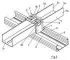
- Fig. 2 in räumlicher Darstellungsweise die Abschnitte zweier Profilschienen, die durch einen Kreuzverbinder gemäß Fig. 1 miteinander verbunden sind, wobei die obere UA-Profilschiene nach oben geöffnet ist, und
- Fig. 3 ebenfalls in räumlicher Darstellungsweise eine Verbindung ähnlich der Fig. 2, wobei jedoch die obere UA-Profilschiene nach unten geöffnet ist.
- Der in der Zeichnung dargestellte Kreuzverbinder 1 besteht aus Stahlblech. Er weist eine im üblichen Einsatzfall oben liegende Stegplatte 2 auf, deren entgegengesetzte Ränder jeweils eine Biegekante 3 bilden, an der jeweils ein Verbinderschenkel 4 rechtwinklig nach unten abgekantet ist.
- Der Kreuzverbinder 1 dient zur Verbindung von zwei aufeinander liegenden, im wesentlichen U-förmigen Profilschienen 5 und 6, wie in den Fig. 2 und 3 dargestellt ist. Diese Profilschienen 5 und 6 bilden beispielsweise einen Teil einer abgehängten Unterdecke. Hierbei liegt die Stegplatte 2 an der Oberseite der jeweils oberen Profilschiene 5 an, während seitliche Hakenvorsprünge 7 der Verbinderschenkel 4 in die jeweils untere Profilschiene 6 eingehakt sind. Diese untere Profilschiene 6 ist als CD-Profilschiene ausgeführt und weist gegeneinander vorspringende Profilränder 8 auf, unter die die seitlichen Hakenvorsprünge 7 greifen, wie in den Fig. 2 und 3 dargestellt ist.
- Aus der Stegplatte 2 des Kreuzverbinders 1 sind zwei Federzungen 9 ausgestanzt und jeweils an einer Biegekante 10 leicht nach unten abgewinkelt.
- Die beiden Biegekanten 10 erstrecken sich rechtwinklig zu dem jeweils benachbarten Verbinderschenkel 4. Jede Federzunge 9 ist aus einer Öffnung 11 ausgestanzt, die sich aus der Stegplatte 2 bis in den jeweils angrenzenden Verbinderschenkel erstreckt. Jede Federzunge 9 ragt seitlich über die Ebene des Verbinderschenkels 4 hinaus.
- Der sich über die Ebene des Verbinderschenkels 4 erstreckende Abschnitt 9a jeder Federzunge 9 beträgt etwa 10% - 25% der Breite der gesamten Federzunge 9.
- Die beiden Öffnungen 11, aus denen die Federzungen 9 ausgestanzt sind, fluchten beim dargestellten Ausführungsbeispiel miteinander. Zwischen ihnen verbleibt ein Blechsteg 2a der Stegplatte 2.
- Die beiden Biegekanten 10, an denen die Federzungen 9 abgewinkelt sind, sind symmetrisch zueinander gegenüber der Mitte der Stegplatte 2 versetzt, so dass auch die Federzungen 9 symmetrisch zueinander angeordnet sind. Dadurch sind auch die von den Federzungen 9 auf den Kreuzverbinder 1 rückwirkenden Federkräfte symmetrisch.
- Aus der Stegplatte 2 erstrecken sich mindestens eine, beim dargestellten Ausführungsbeispiel mehrere parallele Verstärkungssicken 12, vorzugsweise rechtwinklig zur Biegekante 10 und über diese hinaus in die jeweilige Federzunge 9. Dadurch wird auch bei Verwendung von verhältnismäßig dünnem Blech eine ausreichend hohe Federkraft der Federzungen 9 erreicht.
- Wie in den Fig. 2 und 3 gezeigt, ist die jeweils obere Profilschiene 5 ein UA-Profil, dessen beide Profilflansche jeweils eine glatte, gerade Profilkante 5b aufweisen. Wenn diese obere Profilschiene 5 - wie in Fig. 2 gezeigt - so angeordnet ist, dass sie nach oben offen ist, dann drücken die Endkanten 9b der Federzungen 9 auf die Profilkanten 5b. Die Endkanten 9b erstrecken sich hierbei quer zu den Profilkanten 5b und verlaufen somit senkrecht zu den Verbinderschenkeln 4. Auch bei Verformungen oder Maßabweichungen der oberen Profilschiene 5 ist eine sichere Auflage der Federzungen 9 auf der Profilschiene 5 gewährleistet.
- Fig. 3 zeigt, dass die obere Profilschiene 5 auch in umgekehrter Stellung, nämlich nach unten geöffnet, angeordnet werden kann. Die beiden Federzungen 9 drücken hierbei auf die Ränder des Profilstegs 5c der Profilschiene 5.
- Um das Abkanten der Verbinderschenkel 4 von der Stegplatte 2 zu erleichtern, ist vorgesehen, dass sich an der den Verbinderschenkel 4 mit der Stegplatte 2 verbindenden Biegekante 3 seitliche Kerben 13 bzw. 14 von den Außenrändern 15 des Kreuzverbinders 1 und/oder der Öffnung 11 vorspringen, aus der die Federzunge 9 ausgestanzt ist.
Claims (8)
- Kreuzverbinder (1) für zwei aufeinander liegende, sich rechtwinklig kreuzende U- und/oder C-Profilschienen (5, 6), wobei der Kreuzverbinder (1) aus Stahlblech eine oben liegende Stegplatte (2) aufweist, von der zwei Verbinderschenkel (4) rechtwinklig nach unten abgewinkelt sind und seitliche Hakenvorsprünge (7) aufweisen, die in die untere Profilschiene (6) einhakbar sind, und wobei aus der Stegplatte (2) mindestens zwei Federzungen (9) ausgestanzt sind, dadurch gekennzeichnet, dass jede Federzunge (9) jeweils an einer rechtwinklig zu dem benachbarten Verbinderschenkel (4) verlaufenden Biegekante (10) mit der Stegplatte (2) verbunden ist und seitlich über die Ebene des Verbinderschenkels (4) hinausragt.
- Kreuzverbinder nach Anspruch 1, dadurch gekennzeichnet, dass die Federzunge (9) aus einer Öffnung (11) ausgestanzt ist, die sich aus der Stegplatte (2) bis in den angrenzenden Verbinderschenkel (4) erstreckt.
- Kreuzverbinder nach Anspruch 2, dadurch gekennzeichnet, dass die beiden Öffnungen (11) aus denen die Federzungen (9) ausgestanzt sind, miteinander fluchten und zwischen ihnen ein Blechsteg (2a) verbleibt.
- Kreuzverbinder nach Anspruch 1, dadurch gekennzeichnet, dass sich mindestens eine Verstärkungssicke (12) aus der Stegplatte (2) über die Biegekante (10) bis in die Federzunge (9) erstreckt.
- Kreuzverbinder nach Anspruch 4, dadurch gekennzeichnet, dass die Verstärkungssicke (12) rechtwinklig zur Biegekante (10) verläuft.
- Kreuzverbinder nach Anspruch 4, dadurch gekennzeichnet, dass sich mehrere parallele Verstärkungssicken (12) aus der Stegplatte (2) über die Biegekante (10) in die Federzunge (9) erstrecken.
- Kreuzverbinder nach Anspruch 1, dadurch gekennzeichnet, dass der sich über die Ebene des Verbinderschenkels (4) erstreckende Abschnitt (9a) der Federzunge (9) etwa 10% - 25% der Breite der Federzunge (9) beträgt.
- Kreuzverbinder nach Anspruch 1, dadurch gekennzeichnet, dass sich an der den Verbinderschenkel (4) mit der Stegplatte (2) verbindenden Biegekante (3) seitliche Kerben (13 bzw. 14) von den Außenrändern (15) des Kreuzverbinders (1) und/oder der Öffnung (11) vorspringen, aus der die Federzunge (9) ausgestanzt ist.
Priority Applications (1)
| Application Number | Priority Date | Filing Date | Title |
|---|---|---|---|
| SI200331723T SI1413692T1 (sl) | 2002-10-24 | 2003-10-21 | KriĹľni spojnik |
Applications Claiming Priority (2)
| Application Number | Priority Date | Filing Date | Title |
|---|---|---|---|
| DE10249783A DE10249783B3 (de) | 2002-10-24 | 2002-10-24 | Kreuzverbinder |
| DE10249783 | 2002-10-24 |
Publications (2)
| Publication Number | Publication Date |
|---|---|
| EP1413692A1 true EP1413692A1 (de) | 2004-04-28 |
| EP1413692B1 EP1413692B1 (de) | 2009-12-02 |
Family
ID=29796646
Family Applications (1)
| Application Number | Title | Priority Date | Filing Date |
|---|---|---|---|
| EP03024197A Expired - Lifetime EP1413692B1 (de) | 2002-10-24 | 2003-10-21 | Kreuzverbinder |
Country Status (6)
| Country | Link |
|---|---|
| EP (1) | EP1413692B1 (de) |
| AT (1) | ATE450675T1 (de) |
| DE (2) | DE10249783B3 (de) |
| DK (1) | DK1413692T3 (de) |
| ES (1) | ES2335201T3 (de) |
| SI (1) | SI1413692T1 (de) |
Cited By (3)
| Publication number | Priority date | Publication date | Assignee | Title |
|---|---|---|---|---|
| WO2007147557A1 (de) | 2006-06-20 | 2007-12-27 | Richter System Gmbh & Co. Kg | Verbindungselement für c-profile mit ausgleichsmittel und anordnung |
| DE102010016141A1 (de) | 2010-03-25 | 2011-09-29 | Protektorwerk Florenz Maisch Gmbh & Co. Kg | Verbindungssystem für zwei kreuzende C-Profile |
| US10385896B2 (en) * | 2017-07-05 | 2019-08-20 | Brandon C. Winn | Precursor for a furring channel clip, furring channel clip formed therefrom, method of making a furring channel clip, and method of mounting a furring channel to a load bearing member |
Families Citing this family (3)
| Publication number | Priority date | Publication date | Assignee | Title |
|---|---|---|---|---|
| FR2888623B1 (fr) * | 2005-07-18 | 2007-10-05 | Const Electr De La Seine Ces S | Systeme de fixation d'un profile |
| DE102011015435A1 (de) * | 2011-03-29 | 2012-10-04 | Protektorwerk Florenz Maisch Gmbh & Co. Kg | Verbindungselement und Verfahren zu dessen Herstellung |
| ITAN20120127A1 (it) * | 2012-10-08 | 2014-04-09 | Akifix S P A | Staffa pieghevole per la realizzazione di un cavallotto perfezionato destinato a collegare due profilati. |
Citations (4)
| Publication number | Priority date | Publication date | Assignee | Title |
|---|---|---|---|---|
| DE29612593U1 (de) * | 1996-07-20 | 1996-10-17 | Richter-System GmbH & Co KG, 64347 Griesheim | Kreuzverbinder für CD-Schienen |
| DE29822806U1 (de) * | 1998-12-22 | 1999-03-11 | Geipel Decken- und Profilsysteme GmbH, 07806 Neustadt | Kreuzschnellverbinder für CD-Deckenprofile |
| DE19753711A1 (de) * | 1997-12-04 | 1999-06-10 | Huwer Kg | Kreuzverbinder |
| DE29910957U1 (de) * | 1999-06-23 | 1999-10-14 | Richter-System GmbH & Co KG, 64347 Griesheim | Kreuzverbinder für CD-Schienen |
Family Cites Families (2)
| Publication number | Priority date | Publication date | Assignee | Title |
|---|---|---|---|---|
| DE9304348U1 (de) * | 1992-12-01 | 1993-05-13 | Vogl, Erich R., 8535 Emskirchen | U-förmiges Verbindungselement zur Verbindung von C-Profilschienen aus Metall |
| DE29606746U1 (de) * | 1996-04-13 | 1996-06-27 | Richter-System GmbH & Co KG, 64347 Griesheim | Kreuzverbinder für CD-Schienen |
-
2002
- 2002-10-24 DE DE10249783A patent/DE10249783B3/de not_active Expired - Fee Related
-
2003
- 2003-10-21 EP EP03024197A patent/EP1413692B1/de not_active Expired - Lifetime
- 2003-10-21 AT AT03024197T patent/ATE450675T1/de active
- 2003-10-21 DE DE50312179T patent/DE50312179D1/de not_active Expired - Lifetime
- 2003-10-21 ES ES03024197T patent/ES2335201T3/es not_active Expired - Lifetime
- 2003-10-21 SI SI200331723T patent/SI1413692T1/sl unknown
- 2003-10-21 DK DK03024197.0T patent/DK1413692T3/da active
Patent Citations (4)
| Publication number | Priority date | Publication date | Assignee | Title |
|---|---|---|---|---|
| DE29612593U1 (de) * | 1996-07-20 | 1996-10-17 | Richter-System GmbH & Co KG, 64347 Griesheim | Kreuzverbinder für CD-Schienen |
| DE19753711A1 (de) * | 1997-12-04 | 1999-06-10 | Huwer Kg | Kreuzverbinder |
| DE29822806U1 (de) * | 1998-12-22 | 1999-03-11 | Geipel Decken- und Profilsysteme GmbH, 07806 Neustadt | Kreuzschnellverbinder für CD-Deckenprofile |
| DE29910957U1 (de) * | 1999-06-23 | 1999-10-14 | Richter-System GmbH & Co KG, 64347 Griesheim | Kreuzverbinder für CD-Schienen |
Cited By (3)
| Publication number | Priority date | Publication date | Assignee | Title |
|---|---|---|---|---|
| WO2007147557A1 (de) | 2006-06-20 | 2007-12-27 | Richter System Gmbh & Co. Kg | Verbindungselement für c-profile mit ausgleichsmittel und anordnung |
| DE102010016141A1 (de) | 2010-03-25 | 2011-09-29 | Protektorwerk Florenz Maisch Gmbh & Co. Kg | Verbindungssystem für zwei kreuzende C-Profile |
| US10385896B2 (en) * | 2017-07-05 | 2019-08-20 | Brandon C. Winn | Precursor for a furring channel clip, furring channel clip formed therefrom, method of making a furring channel clip, and method of mounting a furring channel to a load bearing member |
Also Published As
| Publication number | Publication date |
|---|---|
| DE10249783B3 (de) | 2004-01-29 |
| DE50312179D1 (de) | 2010-01-14 |
| EP1413692B1 (de) | 2009-12-02 |
| ES2335201T3 (es) | 2010-03-23 |
| SI1413692T1 (sl) | 2010-02-26 |
| DK1413692T3 (da) | 2010-02-15 |
| ATE450675T1 (de) | 2009-12-15 |
Similar Documents
| Publication | Publication Date | Title |
|---|---|---|
| EP0999321B1 (de) | Fussbodenpaneel | |
| EP3540305B1 (de) | System zur realisierung eines lichtbands | |
| EP1413692B1 (de) | Kreuzverbinder | |
| WO2010037777A1 (de) | Steckverbinder | |
| DE29606746U1 (de) | Kreuzverbinder für CD-Schienen | |
| EP0315936B1 (de) | Klotzteil zum Festsetzen von Glasscheiben od. dgl. | |
| EP1065770B1 (de) | Leitungsführungskanal | |
| EP1411182B1 (de) | Vorrichtung zum Verbinden zweier Schienen einer abgehängten Decke | |
| EP0217268A2 (de) | Rechteckförmiges Deckenelement für eine Unterdecke | |
| DE202016102338U1 (de) | Abhänger für Deckenkonstruktionen | |
| DE10028302B4 (de) | Kreuzverbinder für CD-Schienen | |
| EP0388575A1 (de) | Schneehalter | |
| DE29617249U1 (de) | Abhänger für CD-Schienen | |
| EP0639681A2 (de) | Abhänger für T-Profilschienen | |
| EP0271075B1 (de) | Anschlussprofil für Wand- und Deckenpaneele | |
| EP0223802B1 (de) | Kreuzverbinder für c-profilschienen von unterdecken | |
| DE29612593U1 (de) | Kreuzverbinder für CD-Schienen | |
| WO1998028505A1 (de) | Mehrzweck-abhänger für c-profilschienen | |
| DE3610377C2 (de) | ||
| DE202006004608U1 (de) | Verbindungsanordnung für einen Lamellen aufweisenden Raffstore o.dgl. | |
| DE2334860C3 (de) | Zur Bildung von Regalen dienende Trennwand | |
| DE19817080C2 (de) | Montageschiene | |
| DE2109596C3 (de) | Traggerippe für eine Unterdecke oder dergleichen | |
| DE4021773A1 (de) | Schaltschrank mit einem durch wandelemente und tueren abdeckbaren geruest | |
| WO2003023921B1 (de) | Schaltschrank |
Legal Events
| Date | Code | Title | Description |
|---|---|---|---|
| PUAI | Public reference made under article 153(3) epc to a published international application that has entered the european phase |
Free format text: ORIGINAL CODE: 0009012 |
|
| AK | Designated contracting states |
Kind code of ref document: A1 Designated state(s): AT BE BG CH CY CZ DE DK EE ES FI FR GB GR HU IE IT LI LU MC NL PT RO SE SI SK TR |
|
| AX | Request for extension of the european patent |
Extension state: AL LT LV MK |
|
| 17P | Request for examination filed |
Effective date: 20041025 |
|
| AKX | Designation fees paid |
Designated state(s): AT BE BG CH CY CZ DE DK EE ES FI FR GB GR HU IE IT LI LU MC NL PT RO SE SI SK TR |
|
| AXX | Extension fees paid |
Extension state: MK Payment date: 20041025 Extension state: LV Payment date: 20041025 |
|
| GRAP | Despatch of communication of intention to grant a patent |
Free format text: ORIGINAL CODE: EPIDOSNIGR1 |
|
| GRAS | Grant fee paid |
Free format text: ORIGINAL CODE: EPIDOSNIGR3 |
|
| GRAA | (expected) grant |
Free format text: ORIGINAL CODE: 0009210 |
|
| AK | Designated contracting states |
Kind code of ref document: B1 Designated state(s): AT BE BG CH CY CZ DE DK EE ES FI FR GB GR HU IE IT LI LU MC NL PT RO SE SI SK TR |
|
| AX | Request for extension of the european patent |
Extension state: LV MK |
|
| REG | Reference to a national code |
Ref country code: GB Ref legal event code: FG4D Free format text: NOT ENGLISH |
|
| REG | Reference to a national code |
Ref country code: CH Ref legal event code: EP |
|
| REG | Reference to a national code |
Ref country code: IE Ref legal event code: FG4D |
|
| REG | Reference to a national code |
Ref country code: RO Ref legal event code: EPE |
|
| REF | Corresponds to: |
Ref document number: 50312179 Country of ref document: DE Date of ref document: 20100114 Kind code of ref document: P |
|
| REG | Reference to a national code |
Ref country code: SE Ref legal event code: TRGR |
|
| REG | Reference to a national code |
Ref country code: DK Ref legal event code: T3 |
|
| REG | Reference to a national code |
Ref country code: GR Ref legal event code: EP Ref document number: 20100400087 Country of ref document: GR |
|
| REG | Reference to a national code |
Ref country code: ES Ref legal event code: FG2A Ref document number: 2335201 Country of ref document: ES Kind code of ref document: T3 |
|
| REG | Reference to a national code |
Ref country code: NL Ref legal event code: VDEP Effective date: 20091202 |
|
| PG25 | Lapsed in a contracting state [announced via postgrant information from national office to epo] |
Ref country code: FI Free format text: LAPSE BECAUSE OF FAILURE TO SUBMIT A TRANSLATION OF THE DESCRIPTION OR TO PAY THE FEE WITHIN THE PRESCRIBED TIME-LIMIT Effective date: 20091202 |
|
| REG | Reference to a national code |
Ref country code: SK Ref legal event code: T3 Ref document number: E 6686 Country of ref document: SK |
|
| REG | Reference to a national code |
Ref country code: HU Ref legal event code: AG4A Ref document number: E007173 Country of ref document: HU |
|
| PG25 | Lapsed in a contracting state [announced via postgrant information from national office to epo] |
Ref country code: CY Free format text: LAPSE BECAUSE OF FAILURE TO SUBMIT A TRANSLATION OF THE DESCRIPTION OR TO PAY THE FEE WITHIN THE PRESCRIBED TIME-LIMIT Effective date: 20091202 |
|
| REG | Reference to a national code |
Ref country code: IE Ref legal event code: FD4D |
|
| PG25 | Lapsed in a contracting state [announced via postgrant information from national office to epo] |
Ref country code: NL Free format text: LAPSE BECAUSE OF FAILURE TO SUBMIT A TRANSLATION OF THE DESCRIPTION OR TO PAY THE FEE WITHIN THE PRESCRIBED TIME-LIMIT Effective date: 20091202 Ref country code: IE Free format text: LAPSE BECAUSE OF FAILURE TO SUBMIT A TRANSLATION OF THE DESCRIPTION OR TO PAY THE FEE WITHIN THE PRESCRIBED TIME-LIMIT Effective date: 20091202 |
|
| PLBE | No opposition filed within time limit |
Free format text: ORIGINAL CODE: 0009261 |
|
| STAA | Information on the status of an ep patent application or granted ep patent |
Free format text: STATUS: NO OPPOSITION FILED WITHIN TIME LIMIT |
|
| 26N | No opposition filed |
Effective date: 20100903 |
|
| PGFP | Annual fee paid to national office [announced via postgrant information from national office to epo] |
Ref country code: GB Payment date: 20101021 Year of fee payment: 8 |
|
| PG25 | Lapsed in a contracting state [announced via postgrant information from national office to epo] |
Ref country code: MC Free format text: LAPSE BECAUSE OF NON-PAYMENT OF DUE FEES Effective date: 20101031 |
|
| REG | Reference to a national code |
Ref country code: CH Ref legal event code: PL |
|
| PG25 | Lapsed in a contracting state [announced via postgrant information from national office to epo] |
Ref country code: CH Free format text: LAPSE BECAUSE OF NON-PAYMENT OF DUE FEES Effective date: 20101031 Ref country code: LI Free format text: LAPSE BECAUSE OF NON-PAYMENT OF DUE FEES Effective date: 20101031 |
|
| PGFP | Annual fee paid to national office [announced via postgrant information from national office to epo] |
Ref country code: HU Payment date: 20111018 Year of fee payment: 9 Ref country code: DK Payment date: 20111024 Year of fee payment: 9 Ref country code: EE Payment date: 20111021 Year of fee payment: 9 Ref country code: BG Payment date: 20111024 Year of fee payment: 9 Ref country code: BE Payment date: 20111024 Year of fee payment: 9 |
|
| PG25 | Lapsed in a contracting state [announced via postgrant information from national office to epo] |
Ref country code: LU Free format text: LAPSE BECAUSE OF NON-PAYMENT OF DUE FEES Effective date: 20101021 |
|
| BERE | Be: lapsed |
Owner name: RICHTER-SYSTEM G.M.B.H. & CO. KG Effective date: 20121031 |
|
| REG | Reference to a national code |
Ref country code: DK Ref legal event code: EBP |
|
| REG | Reference to a national code |
Ref country code: EE Ref legal event code: MM4A Ref document number: E004080 Country of ref document: EE Effective date: 20121031 |
|
| GBPC | Gb: european patent ceased through non-payment of renewal fee |
Effective date: 20121021 |
|
| PG25 | Lapsed in a contracting state [announced via postgrant information from national office to epo] |
Ref country code: EE Free format text: LAPSE BECAUSE OF NON-PAYMENT OF DUE FEES Effective date: 20121031 Ref country code: BE Free format text: LAPSE BECAUSE OF NON-PAYMENT OF DUE FEES Effective date: 20121031 Ref country code: GB Free format text: LAPSE BECAUSE OF NON-PAYMENT OF DUE FEES Effective date: 20121021 |
|
| PG25 | Lapsed in a contracting state [announced via postgrant information from national office to epo] |
Ref country code: HU Free format text: LAPSE BECAUSE OF NON-PAYMENT OF DUE FEES Effective date: 20121022 |
|
| PG25 | Lapsed in a contracting state [announced via postgrant information from national office to epo] |
Ref country code: DK Free format text: LAPSE BECAUSE OF NON-PAYMENT OF DUE FEES Effective date: 20121031 |
|
| PG25 | Lapsed in a contracting state [announced via postgrant information from national office to epo] |
Ref country code: BG Free format text: LAPSE BECAUSE OF NON-PAYMENT OF DUE FEES Effective date: 20121031 Ref country code: PT Free format text: LAPSE BECAUSE OF NON-PAYMENT OF DUE FEES Effective date: 20100402 |
|
| PGFP | Annual fee paid to national office [announced via postgrant information from national office to epo] |
Ref country code: ES Payment date: 20141024 Year of fee payment: 12 Ref country code: RO Payment date: 20141016 Year of fee payment: 12 Ref country code: FR Payment date: 20141021 Year of fee payment: 12 Ref country code: CZ Payment date: 20141015 Year of fee payment: 12 Ref country code: SK Payment date: 20141017 Year of fee payment: 12 |
|
| PGFP | Annual fee paid to national office [announced via postgrant information from national office to epo] |
Ref country code: SI Payment date: 20141010 Year of fee payment: 12 Ref country code: AT Payment date: 20141030 Year of fee payment: 12 |
|
| PGFP | Annual fee paid to national office [announced via postgrant information from national office to epo] |
Ref country code: SE Payment date: 20151026 Year of fee payment: 13 |
|
| REG | Reference to a national code |
Ref country code: AT Ref legal event code: MM01 Ref document number: 450675 Country of ref document: AT Kind code of ref document: T Effective date: 20151021 |
|
| REG | Reference to a national code |
Ref country code: SK Ref legal event code: MM4A Ref document number: E 6686 Country of ref document: SK Effective date: 20151021 |
|
| PG25 | Lapsed in a contracting state [announced via postgrant information from national office to epo] |
Ref country code: CZ Free format text: LAPSE BECAUSE OF NON-PAYMENT OF DUE FEES Effective date: 20151021 |
|
| REG | Reference to a national code |
Ref country code: FR Ref legal event code: ST Effective date: 20160630 Ref country code: SI Ref legal event code: KO00 Effective date: 20160630 |
|
| PG25 | Lapsed in a contracting state [announced via postgrant information from national office to epo] |
Ref country code: FR Free format text: LAPSE BECAUSE OF NON-PAYMENT OF DUE FEES Effective date: 20151102 Ref country code: AT Free format text: LAPSE BECAUSE OF NON-PAYMENT OF DUE FEES Effective date: 20151021 Ref country code: SK Free format text: LAPSE BECAUSE OF NON-PAYMENT OF DUE FEES Effective date: 20151021 Ref country code: RO Free format text: LAPSE BECAUSE OF NON-PAYMENT OF DUE FEES Effective date: 20151021 Ref country code: SI Free format text: LAPSE BECAUSE OF NON-PAYMENT OF DUE FEES Effective date: 20151022 |
|
| PG25 | Lapsed in a contracting state [announced via postgrant information from national office to epo] |
Ref country code: ES Free format text: LAPSE BECAUSE OF NON-PAYMENT OF DUE FEES Effective date: 20151022 |
|
| PG25 | Lapsed in a contracting state [announced via postgrant information from national office to epo] |
Ref country code: SE Free format text: LAPSE BECAUSE OF NON-PAYMENT OF DUE FEES Effective date: 20161022 |
|
| REG | Reference to a national code |
Ref country code: DE Ref legal event code: R082 Ref document number: 50312179 Country of ref document: DE |
|
| PGFP | Annual fee paid to national office [announced via postgrant information from national office to epo] |
Ref country code: TR Payment date: 20211012 Year of fee payment: 19 Ref country code: DE Payment date: 20211027 Year of fee payment: 19 |
|
| PGFP | Annual fee paid to national office [announced via postgrant information from national office to epo] |
Ref country code: IT Payment date: 20211021 Year of fee payment: 19 Ref country code: GR Payment date: 20211027 Year of fee payment: 19 |
|
| REG | Reference to a national code |
Ref country code: DE Ref legal event code: R119 Ref document number: 50312179 Country of ref document: DE |
|
| PG25 | Lapsed in a contracting state [announced via postgrant information from national office to epo] |
Ref country code: DE Free format text: LAPSE BECAUSE OF NON-PAYMENT OF DUE FEES Effective date: 20230503 |
|
| PG25 | Lapsed in a contracting state [announced via postgrant information from national office to epo] |
Ref country code: GR Free format text: LAPSE BECAUSE OF NON-PAYMENT OF DUE FEES Effective date: 20230508 |
|
| PG25 | Lapsed in a contracting state [announced via postgrant information from national office to epo] |
Ref country code: IT Free format text: LAPSE BECAUSE OF NON-PAYMENT OF DUE FEES Effective date: 20221021 |
|
| PG25 | Lapsed in a contracting state [announced via postgrant information from national office to epo] |
Ref country code: TR Free format text: LAPSE BECAUSE OF NON-PAYMENT OF DUE FEES Effective date: 20221021 |