EP1412239B1 - Hauptbremszylinder mit gegenüberliegenden kolben - Google Patents
Hauptbremszylinder mit gegenüberliegenden kolben Download PDFInfo
- Publication number
- EP1412239B1 EP1412239B1 EP02742522A EP02742522A EP1412239B1 EP 1412239 B1 EP1412239 B1 EP 1412239B1 EP 02742522 A EP02742522 A EP 02742522A EP 02742522 A EP02742522 A EP 02742522A EP 1412239 B1 EP1412239 B1 EP 1412239B1
- Authority
- EP
- European Patent Office
- Prior art keywords
- pistons
- cylinder
- brake cylinder
- brake
- piston
- Prior art date
- Legal status (The legal status is an assumption and is not a legal conclusion. Google has not performed a legal analysis and makes no representation as to the accuracy of the status listed.)
- Expired - Lifetime
Links
- 238000006243 chemical reaction Methods 0.000 claims abstract description 16
- 239000012530 fluid Substances 0.000 claims abstract description 8
- 230000000712 assembly Effects 0.000 claims abstract description 5
- 238000000429 assembly Methods 0.000 claims abstract description 5
- 230000009977 dual effect Effects 0.000 claims abstract description 4
- 239000007787 solid Substances 0.000 claims abstract description 4
- 238000006073 displacement reaction Methods 0.000 claims abstract description 3
- 238000004891 communication Methods 0.000 claims description 2
- 230000001105 regulatory effect Effects 0.000 claims 1
- 238000007789 sealing Methods 0.000 claims 1
- 238000000034 method Methods 0.000 description 11
- 238000010276 construction Methods 0.000 description 3
- 238000013461 design Methods 0.000 description 3
- 235000014676 Phragmites communis Nutrition 0.000 description 2
- 238000010348 incorporation Methods 0.000 description 2
- 239000000463 material Substances 0.000 description 2
- 238000012986 modification Methods 0.000 description 2
- 230000004048 modification Effects 0.000 description 2
- XAGFODPZIPBFFR-UHFFFAOYSA-N aluminium Chemical compound [Al] XAGFODPZIPBFFR-UHFFFAOYSA-N 0.000 description 1
- 229910052782 aluminium Inorganic materials 0.000 description 1
- 239000004411 aluminium Substances 0.000 description 1
- 238000005266 casting Methods 0.000 description 1
- 230000006835 compression Effects 0.000 description 1
- 238000007906 compression Methods 0.000 description 1
- 230000014759 maintenance of location Effects 0.000 description 1
- 238000004519 manufacturing process Methods 0.000 description 1
- 238000004137 mechanical activation Methods 0.000 description 1
- 238000010137 moulding (plastic) Methods 0.000 description 1
- 230000000717 retained effect Effects 0.000 description 1
Images


Classifications
-
- B—PERFORMING OPERATIONS; TRANSPORTING
- B60—VEHICLES IN GENERAL
- B60T—VEHICLE BRAKE CONTROL SYSTEMS OR PARTS THEREOF; BRAKE CONTROL SYSTEMS OR PARTS THEREOF, IN GENERAL; ARRANGEMENT OF BRAKING ELEMENTS ON VEHICLES IN GENERAL; PORTABLE DEVICES FOR PREVENTING UNWANTED MOVEMENT OF VEHICLES; VEHICLE MODIFICATIONS TO FACILITATE COOLING OF BRAKES
- B60T11/00—Transmitting braking action from initiating means to ultimate brake actuator without power assistance or drive or where such assistance or drive is irrelevant
- B60T11/10—Transmitting braking action from initiating means to ultimate brake actuator without power assistance or drive or where such assistance or drive is irrelevant transmitting by fluid means, e.g. hydraulic
- B60T11/16—Master control, e.g. master cylinders
- B60T11/20—Tandem, side-by-side, or other multiple master cylinder units
-
- B—PERFORMING OPERATIONS; TRANSPORTING
- B60—VEHICLES IN GENERAL
- B60T—VEHICLE BRAKE CONTROL SYSTEMS OR PARTS THEREOF; BRAKE CONTROL SYSTEMS OR PARTS THEREOF, IN GENERAL; ARRANGEMENT OF BRAKING ELEMENTS ON VEHICLES IN GENERAL; PORTABLE DEVICES FOR PREVENTING UNWANTED MOVEMENT OF VEHICLES; VEHICLE MODIFICATIONS TO FACILITATE COOLING OF BRAKES
- B60T17/00—Component parts, details, or accessories of power brake systems not covered by groups B60T8/00, B60T13/00 or B60T15/00, or presenting other characteristic features
- B60T17/18—Safety devices; Monitoring
Definitions
- This invention relates to master cylinders for hydraulic brake systems for vehicles and in particular, to a divided master cylinder constructed with dual opposing pistons whereby if one of the sides of the master cylinder or the hydraulic circuit componentry, seals, or hoses should fail, the other side of the master cylinder and its corresponding hydraulic circuit will maintain the braking operation.
- a major problem with braking systems for motor vehicles and like vehicles is the failure of hydraulic pressure due to seal leaks, hose failure and the like whereby due to the lack of hydraulic pressure the brakes are unable to operate in an effective manner. Such lack of operation can be catastrophic and lead to fatalities.
- a major disadvantage of currently manufactured tandem brake master cylinders is the length of cylinder body housing. This is both costly to manufacture as well as encroaching on limited engine compartment space. Current designs also use a single sliding elastomeric rubber seal to divide the primary and secondary sections. The use of such a seal results in increased pedal travel due to seal compression and deflection and reduced secondary section output pressure due to frictional losses.
- One further possible drawback is that in the unlikely event of two problems arising simultaneously, such as a hose failure and the dividing seal failure, total loss of brake fluid could occur with corresponding total loss of vehicle braking.
- GB635901 discloses a brake cylinder with opposing pistons to provide a dual or tandem system with the features of the preamble of claim 1.
- a brake cylinder apparatus for vehicles, said brake apparatus having a cylinder with at least two sections with at least two separate delivery connections, at least two pistons being displaced by the action of an operational means, whereby if there is a failure in one of the cylinders and/or delivery connections or braking components, the action of the remaining pistons in communication with the remaining delivery connections maintains hydraulic pressure to the brakes of the vehicle.
- the two sections of the cylinder are separated by a solid dividing wall whereby the two pistons are each located in a separate section with each section having a delivery connection associated therewith.
- the pistons are operated by the action of a brake pedal which transmits mechanical force, often with the assistance of a brake booster, so the piston's whole force creates hydraulic pressure which communicates with disc brake calipers and/or drum brakes associated with the vehicle wheels such that each delivery connection is connected via a divided system applicable to the particular vehicle type.
- the master brake cylinder with opposing pistons includes a main body portion being generally slidingly received and supported and being able to float longitudinally.
- the main body portion of the cylinder includes the two sections of the tandem cylinder divided by the dividing wall. These two sections are commonly known as the primary and secondary sections, within which there is a primary and secondary piston associated.
- the main body support system can also include a reaction beam, which forms the reaction point for the secondary piston.
- a reaction beam which forms the reaction point for the secondary piston.
- it may be an adjustable or fixed stop, depending on the preferred method of construction.
- a first one of the pistons received in a first one of the sections is operated by a first push rod associated with the brake pedal and a second one of the pistons received in a second one of the two sections, usually known as the secondary section, and having its action opposed to the action of the first piston, the second piston being operated by a second push rod received at the opposite end by the reaction beam as the main body slides longitudinally against the second push rod following operation of the brake pedal.
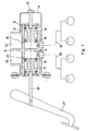
- a preferred embodiment of a brake cylinder apparatus 10 of the present invention as seen in Fig. 1 includes a main portion 11 which is slidingly received within an outer carrier 12 which is preferably bolted to a firewall or a brake booster within the engine compartment of a motor vehicle (not illustrated).
- the outer carrier 12 has an adjustable screw 13 partially received within its distal end 14, the amount of the screw 13 protruding into the outer carrier 12 being adjustable in length.
- the main portion 11 of the apparatus 10 has two opposed piston assemblies 15 and 16 with a dividing wall 17 therebetween such that there are opposed cylinder sections 18 and 19 each with delivery connection outlets 20 and 21 respectively.
- the delivery connection outlets 20 and 21 are connected to the brake caliper/drums such that each of the outlets 20 and 21 connect to all four wheels in known arrangements.
- Hydraulic fluid containers 22 and 23 are shown associated with the two sections 18 and 19 with inlets 24 and 25 being used to fill the two sections 18 and 19 with hydraulic fluid from the containers 22 and 23.
- the piston assembly 15 is operable by a push rod 26 mechanically linked to a brake pedal 27.
- the opposing piston assembly 16 is operable by action against the adj ustable screw 13 as it abuts against it, the screw 13 acting as the push-rod.
- the apparatus 10 operates such that when the apparatus is set up, the push-rod 26 acts against the piston assembly 15 and when during such action, the main portion 11 slides within the outer carrier 12, where the adjustable screw 13 bottoms against the piston assembly 16 forming the two cylinder sections 18 and 19.
- the both piston assemblies Upon application of the brake pedal 27 in normal operation, the both piston assemblies operate in unison as the inner portion 11 floats within the carrier 12. If there is a piston or seal failure in the assemblies 15, the piston assembly pushes against the dividing wall 17 thus pushing the main portion 11 within the carrier 12 against the adjustable screw 13 thus maintaining hydraulic pressure via the delivery connection outlet 21.
- the piston assembly bottoms and pushes against the other side of the dividing wall 17 thus the piston 15 maintains hydraulic pressure via the delivery connection outlet 20.
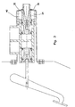
- Fig. 2 shows optional methods of partial system failure indication.
- One system employs a magnetically operated reed switch 28 with magnets 29 and 30 placed in the ends of the primary and secondary pistons respectively. Should either system fail due to a hydraulic leakage within that system, then upon application of the brake pedal the associated piston will bottom in the bore and activate the reed switch.
- An alternate partial system failure indication method employs two spring-loaded contact type switches 31 and 33 positioned such that when either system fails, switch 31 is operated by ramp on piston 32 and switch 33 is operated by the longitudinal displacement of the main body 11.
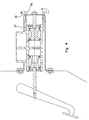
- Fig. 3 shows an optional position for the secondary piston 34 return spring 40.
- Secondary piston 34 is in optional design which allows for incorporation of a proportioning valve or simply a fluid outlet passage 35 through the piston 34.
- Piston 34 is retained in the carrier 12 by a circlip 36 or any other retention method.
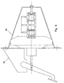
- Fig. 4 shows an alternative design method for proportioning the output pressure from the secondary section.
- Calibrated coil or disc springs 37 are interposed between the main body 11 and the outer carrier 12.
- Worm gear 39 is adjustable or fixed depending on the requirement for fixed or variable proportioning. Should variable proportioning be required, the worm gear 39 can be suitably rotated to provide such output pressure by worm 38 attached to a suitable servo-sensing motor mechanism of either electronic or mechanical activation.
- Fig. 5 shows one suggested method of support and reaction carrier for the brake master cylinder with opposing pistons.
- Elongated studs 41 and 42 are built into the brake booster or alternatively attached to the firewall, a simple reaction carrier 43 is attached to the distal end of studs 41 and 42.
- Fig. 6 shows a total force reaction system employing a carrier 45 attached to the brake pedal support bracket 44 thus eliminating tension loads from the brake booster and tandem cylinder.
- Fig. 7 shows a typical cross section of the master cylinder body 46 which may be manufactured from extruded bar stock, simple aluminium casting on a plastic moulding.
Landscapes
- Engineering & Computer Science (AREA)
- Transportation (AREA)
- Mechanical Engineering (AREA)
- Transmission Of Braking Force In Braking Systems (AREA)
- Braking Arrangements (AREA)
- Carbon And Carbon Compounds (AREA)
- Other Liquid Machine Or Engine Such As Wave Power Use (AREA)
Claims (15)
- Hauptbremszylinder (10) mit gegenüberliegenden Kolben (15, 16), der in einem gemeinsamen Zylinderkörper mit offenen Bohrungen an gegenüberliegenden Enden Dual- oder Tandemsysteme schafft, die vollständig getrennt und einzeln sind, mit:zwei Kolbenanordnungen mit Dichtungskappen oder Tellern, die in den Bohrungen der Zylinder gleitend arbeiten und dann, wenn auf sie eine äußere Kraft einer Schubstange (26) wirkt, einen Hydraulikfluiddruck und eine Hydraulikfluidverlagerung für die Betätigung von Bremssätteln und/oder Trommelbremsen erzeugen, die mit jedem einzelnen Hydrauliksystem verbunden sind;mehreren Federmitteln, die innerhalb oder außerhalb der Zylinderbohrung positioniert sind, um die Kolben in ihre entlasteten Positionen zurückzustellen; undeinem Haltemechanismus zum Halten der Kolben in ihren Bohrungen,dadurch gekennzeichnet, dass der Hauptbremszylinder einen in Längsrichtung schwebenden Hauptzylinderkörper (11) mit einzelnen offenen Bohrungen an gegenüberliegenden Enden, einer gemeinsamen festen geschlossenen Teilungswand (17) und einen äußeren Trägermechanismus (12), um eine Gleitunterstützung für den Zylinderkörper (11) zu schaffen und um eine Reaktionsanordnung zu schaffen, die auf den gegenüberliegenden sekundären Kolben (16) angewendet wird, damit er in seiner Bohrung (19) gleitet, umfasst.
- Hauptbremszylinder (10) mit gegenüberliegenden Kolben (15, 16) nach Anspruch 1, der einen Sekundärkolben (16) umfasst, der an dem Reaktionsträger (12) befestigt ist, wobei der Sekundärkolben einen Fluidauslassanschluss (35) aufweist.
- Hauptbremszylinder (10) mit gegenüberliegenden Kolben (15, 16) nach Anspruch 2, wobei einer der Kolben (15, 16) ein Dosierungsventil enthält.
- Hauptbremszylinder (10) mit gegenüberliegenden Kolben (15, 16) nach Anspruch 3, wobei die befestigte Sekundärkolbenanordnung eine äußere Sekundärkolben-Rückstellfeder verwendet.
- Hauptbremszylinder (10) mit gegenüberliegenden Kolben (15, 16) nach Anspruch 1, wobei die Dosierung des Sekundärbremssystem-Hydraulikausgangsdrucks durch die Kraft einer kalibrierten Feder (37), die zwischen den Reaktionsträger (12) und den Zylinderkörper (11) eingefügt ist, und durch einen einstellbaren Mechanismus (34) zum Verändern der Position der kalibrierten Feder reguliert wird, um seine Kraft auf den Zylinderkörper (11) zu verändern; wodurch der Sekundärabschnitt-Hydraulikausgangsdruck so verändert wird, dass er mit der dynamischen Bremskraftanforderung kompatibel ist.
- Hauptbremszylinder (10) mit gegenüberliegenden Kolben (15, 16) nach Anspruch 1, wobei der Hauptzylinderkörper keinen äußeren Kräften, sondern nur dem inneren Expansionsdruck unterliegt.
- Hauptbremszylinder mit gegenüberliegenden Kolben nach Anspruch 1, wobei mehrere Federmittel, die innerhalb oder außerhalb der Zylinderbohrung positioniert sind, um die Kolben in ihre entlasteten Positionen zurückzustellen, aus Schraubenfedern bestehen.
- Hauptbremszylinder mit gegenüberliegenden Kolben nach Anspruch 1, wobei der Haltemechanismus ein Sicherungsring oder eine Kappe zum Halten der Kolben in ihren Bohrungen ist.
- Bremszylindervorrichtung (10) für Fahrzeuge nach einem der Ansprüche 1-8, wobei die Bremsvorrichtung einen Zylinder (11) umfasst, der wenigstens zwei Abschnitte mit wenigstens zwei getrennten Förderverbindungen und wenigstens zwei Kolben (15, 16), die durch die Wirkung eines Betätigungsmittels verlagert werden, besitzt, wobei dann, wenn in einem der Zylinder und/oder Förderverbindungen oder Bremskomponenten ein Fehler auftritt, die Wirkung der verbleibenden Kolben, die mit den verbleibenden Förderverbindungen in Verbindung stehen, den Hydraulikdruck an den Bremsen des Fahrzeugs aufrecht erhält.
- Bremszylindervorrichtung (10) für Fahrzeuge nach Anspruch 9, wobei die zwei Abschnitte des Zylinders (11) durch eine feste Unterteilungswand (17) getrennt sind, wobei sich die zwei Kolben (15, 16) jeweils in einem getrennten Abschnitt befinden, wobei jeder Abschnitt eine ihm zugeordnete Förderverbindung besitzt.
- Bremszylindervorrichtung (10) für Fahrzeuge nach Anspruch 9, wobei die Kolben (15, 16) durch die Wirkung eines Bremspedals betätigt werden, das eine mechanische Kraft überträgt, so dass die gesamte Kraft des Kolbens einen Hydraulikdruck erzeugt, der mit Scheibenbremsen-Bremssätteln und/oder mit Trommelbremsen, die den Fahrzeugrädern zugeordnet sind, kommuniziert, so dass jede Förderverbindung über ein unterteiltes System, das auf den besonderen Fahrzeugtyp anwendbar ist, verbunden ist.
- Bremszylindervorrichtung (10) für Fahrzeuge nach Anspruch 9, wobei die Bremszylindervorrichtung einen Hauptkörperabschnitt (11), der im Allgemeinen gleitend aufgenommen und unterstützt ist und in Längsrichtung schweben kann, umfasst, wobei der Hauptkörperabschnitt des Zylinders zwei Abschnitte des Tandemzylinders, die durch die Teilungswand unterteilt sind, aufweist, wobei diese beiden Abschnitte ein Primär- und ein Sekundärabschnitt sind, in denen ein Primärkolben (15) bzw. ein Sekundärkolben (16) vorgesehen sind.
- Bremszylindervorrichtung (10) für Fahrzeuge nach Anspruch 9, wobei das Hauptkörperunterstützungssystem einen Reaktionsträger enthält, der den Reaktionspunkt für den Sekundärkolben bildet.
- Bremszylindervorrichtung (10) für Fahrzeuge nach Anspruch 13, wobei der Reaktionsträger einen einstellbaren oder festen Anschlag besitzt.
- Bremszylindervorrichtung (10) für Fahrzeuge nach Anspruch 9, wobei ein Erster der Kolben, der in einem Ersten der Abschnitte aufgenommen ist, durch eine erste Schubstange betätigt wird, die dem Bremspedal zugeordnet ist, und ein Zweiter der Kolben, der in einem Zweiten der zwei Abschnitte aufgenommen ist und dessen Wirkung zu der Wirkung des ersten Kolbens entgegengesetzt ist, über eine zweite Schubstange, die an dem gegenüberliegenden Ende aufgenommen ist, durch den Reaktionsträger betätigt wird, wenn der Hauptkörper in Längsrichtung entgegen der zweiten Schubstange, die der Betätigung des Bremspedals folgt, gleitet.
Applications Claiming Priority (3)
| Application Number | Priority Date | Filing Date | Title |
|---|---|---|---|
| AUPR6655A AUPR665501A0 (en) | 2001-07-27 | 2001-07-27 | Master brake cylinder with opposing pistons |
| AUPR665501 | 2001-07-27 | ||
| PCT/AU2002/000878 WO2003011667A1 (en) | 2001-07-27 | 2002-07-03 | Master brake cylinder with opposing pistons |
Publications (3)
| Publication Number | Publication Date |
|---|---|
| EP1412239A1 EP1412239A1 (de) | 2004-04-28 |
| EP1412239A4 EP1412239A4 (de) | 2005-11-16 |
| EP1412239B1 true EP1412239B1 (de) | 2008-09-10 |
Family
ID=3830611
Family Applications (1)
| Application Number | Title | Priority Date | Filing Date |
|---|---|---|---|
| EP02742522A Expired - Lifetime EP1412239B1 (de) | 2001-07-27 | 2002-07-03 | Hauptbremszylinder mit gegenüberliegenden kolben |
Country Status (7)
| Country | Link |
|---|---|
| US (1) | US7086228B2 (de) |
| EP (1) | EP1412239B1 (de) |
| CN (1) | CN1248889C (de) |
| AT (1) | ATE407856T1 (de) |
| AU (1) | AUPR665501A0 (de) |
| DE (1) | DE60228845D1 (de) |
| WO (1) | WO2003011667A1 (de) |
Families Citing this family (8)
| Publication number | Priority date | Publication date | Assignee | Title |
|---|---|---|---|---|
| US20070182403A1 (en) * | 2003-04-07 | 2007-08-09 | Von Hayn Holger | Device for monitoring the position and displacement of a brake pedal |
| CN102407839A (zh) * | 2011-09-22 | 2012-04-11 | 芜湖恒坤汽车部件有限公司 | 具有一体化油杯的制动主缸总成 |
| CN102518712A (zh) * | 2011-12-09 | 2012-06-27 | 芜湖博格汽车零部件有限公司 | 汽车轮缸 |
| CN103950440B (zh) * | 2014-01-20 | 2017-06-13 | 南京工程学院 | 一种双压制动缸 |
| CN104879403A (zh) * | 2015-06-26 | 2015-09-02 | 芜湖创智机械技术有限公司 | 一种汽车用盘式制动装置 |
| JP6721207B2 (ja) * | 2016-02-16 | 2020-07-08 | 日立オートモティブシステムズ株式会社 | ブレーキ装置、ブレーキシステムおよびマスタシリンダ |
| CN109944967B (zh) * | 2019-03-18 | 2020-01-31 | 温州职业技术学院 | 一种双塞式全开安全阀 |
| US20240217493A1 (en) * | 2022-12-29 | 2024-07-04 | Rivian Ip Holdings, Llc | Remote brake fluid reservoir system |
Family Cites Families (10)
| Publication number | Priority date | Publication date | Assignee | Title |
|---|---|---|---|---|
| US2152065A (en) * | 1935-07-29 | 1939-03-28 | Bendix Prod Corp | Duplex master cylinder |
| BE466537A (de) * | 1942-09-21 | |||
| US2516495A (en) * | 1946-06-10 | 1950-07-25 | Leblond Mach Tool Co R K | Hydraulic tool control unit |
| US3513655A (en) * | 1968-07-18 | 1970-05-26 | Bendix Corp | Spring caging device for master cylinders |
| FR2203730B1 (de) * | 1972-10-25 | 1976-10-29 | Dba | |
| JPS5320069A (en) * | 1976-08-09 | 1978-02-23 | Nissan Motor Co Ltd | Tandem master cylinder |
| US4117681A (en) * | 1977-02-07 | 1978-10-03 | Wagner Electric Corporation | Tandem master cylinder with integral proportioning valve |
| DE2908480A1 (de) * | 1979-03-05 | 1980-10-09 | Teves Gmbh Alfred | Hydraulische bremsbetaetigungseinrichtung fuer kraftfahrzeuge mit einem anti- blockier-system |
| DE2949713A1 (de) * | 1979-12-11 | 1981-06-19 | Daimler-Benz Ag, 7000 Stuttgart | Zweikreis-hauptbremszylinder |
| JPS58188742A (ja) * | 1982-04-30 | 1983-11-04 | Mitsubishi Motors Corp | 油圧発生装置 |
-
2001
- 2001-07-27 AU AUPR6655A patent/AUPR665501A0/en not_active Abandoned
-
2002
- 2002-07-03 AT AT02742522T patent/ATE407856T1/de not_active IP Right Cessation
- 2002-07-03 CN CNB028127846A patent/CN1248889C/zh not_active Expired - Fee Related
- 2002-07-03 DE DE60228845T patent/DE60228845D1/de not_active Expired - Fee Related
- 2002-07-03 EP EP02742522A patent/EP1412239B1/de not_active Expired - Lifetime
- 2002-07-03 US US10/481,310 patent/US7086228B2/en not_active Expired - Fee Related
- 2002-07-03 WO PCT/AU2002/000878 patent/WO2003011667A1/en not_active Ceased
Also Published As
| Publication number | Publication date |
|---|---|
| EP1412239A4 (de) | 2005-11-16 |
| EP1412239A1 (de) | 2004-04-28 |
| ATE407856T1 (de) | 2008-09-15 |
| US7086228B2 (en) | 2006-08-08 |
| US20050088038A1 (en) | 2005-04-28 |
| AUPR665501A0 (en) | 2001-08-16 |
| CN1520364A (zh) | 2004-08-11 |
| WO2003011667A8 (en) | 2004-04-08 |
| CN1248889C (zh) | 2006-04-05 |
| DE60228845D1 (de) | 2008-10-23 |
| WO2003011667A1 (en) | 2003-02-13 |
Similar Documents
| Publication | Publication Date | Title |
|---|---|---|
| EP0956223B1 (de) | Pedalwegsimulator mit feder mit nicht-linearer kraft-weg kennlinie | |
| US8100047B2 (en) | Slip seal diaphragm for spring brake actuator | |
| JP2000501674A (ja) | 道路用車両、特に乗用車のためのハイドロリック式のブレーキ装置 | |
| EP1412239B1 (de) | Hauptbremszylinder mit gegenüberliegenden kolben | |
| US4516400A (en) | Master cylinder assembly for a vehicle braking system | |
| GB2088981A (en) | Brake master cylinder | |
| GB2098687A (en) | A twin master cylinder or booster assembly for a vehicle braking system | |
| AU2002344692B2 (en) | Master brake cylinder with opposing pistons | |
| US4020931A (en) | Accelerator hydraulic control means for friction brakes | |
| US5066940A (en) | Brake pedal travel warning system | |
| US4313642A (en) | Control valve for vehicle brake systems having two brake circuits | |
| US3899889A (en) | Pedal ratio control for hydraulic booster | |
| US11225236B2 (en) | Electric brake booster equipped with a pressure balance detecting device | |
| AU2002344692A1 (en) | Master brake cylinder with opposing pistons | |
| EP2749462B1 (de) | Hydraulisches Bremssystem und Verfahren der Bremsverstärkung in einem Kraftfahrzeug | |
| US10239509B2 (en) | Primary piston assembly for a master brake cylinder of a braking system of a vehicle, manufacturing method for a braking unit, and method for operating a braking unit | |
| US3172265A (en) | Dual-cylinder hydraulic actuator for automotive brake systems | |
| US3731487A (en) | Master cylinder | |
| US3310944A (en) | Master cylinder | |
| US20050225167A1 (en) | Master brake cylinder unit for an electrohydraulic vehicle brake system | |
| US5878574A (en) | Master cylinder having nested concentric pistons | |
| EP0048087B1 (de) | Hydraulik-Hauptzylinder | |
| CN114506304B (zh) | 踏板感模拟装置、电子液压制动系统和机动车 | |
| US3379287A (en) | Plural actuated brake system | |
| SU885638A1 (ru) | Многоконтурна гидравлическа тормозна система транспортного средства |
Legal Events
| Date | Code | Title | Description |
|---|---|---|---|
| PUAI | Public reference made under article 153(3) epc to a published international application that has entered the european phase |
Free format text: ORIGINAL CODE: 0009012 |
|
| 17P | Request for examination filed |
Effective date: 20031218 |
|
| AK | Designated contracting states |
Kind code of ref document: A1 Designated state(s): AT BE BG CH CY CZ DE DK EE ES FI FR GB GR IE IT LI LU MC NL PT SE SK TR |
|
| AX | Request for extension of the european patent |
Extension state: AL LT LV MK RO SI |
|
| A4 | Supplementary search report drawn up and despatched |
Effective date: 20051006 |
|
| RIC1 | Information provided on ipc code assigned before grant |
Ipc: 7B 60T 11/20 A |
|
| 17Q | First examination report despatched |
Effective date: 20061213 |
|
| GRAP | Despatch of communication of intention to grant a patent |
Free format text: ORIGINAL CODE: EPIDOSNIGR1 |
|
| GRAS | Grant fee paid |
Free format text: ORIGINAL CODE: EPIDOSNIGR3 |
|
| GRAA | (expected) grant |
Free format text: ORIGINAL CODE: 0009210 |
|
| AK | Designated contracting states |
Kind code of ref document: B1 Designated state(s): AT BE BG CH CY CZ DE DK EE ES FI FR GB GR IE IT LI LU MC NL PT SE SK TR |
|
| REG | Reference to a national code |
Ref country code: GB Ref legal event code: FG4D |
|
| REG | Reference to a national code |
Ref country code: CH Ref legal event code: EP |
|
| REG | Reference to a national code |
Ref country code: IE Ref legal event code: FG4D |
|
| REF | Corresponds to: |
Ref document number: 60228845 Country of ref document: DE Date of ref document: 20081023 Kind code of ref document: P |
|
| PG25 | Lapsed in a contracting state [announced via postgrant information from national office to epo] |
Ref country code: FI Free format text: LAPSE BECAUSE OF FAILURE TO SUBMIT A TRANSLATION OF THE DESCRIPTION OR TO PAY THE FEE WITHIN THE PRESCRIBED TIME-LIMIT Effective date: 20080910 Ref country code: AT Free format text: LAPSE BECAUSE OF FAILURE TO SUBMIT A TRANSLATION OF THE DESCRIPTION OR TO PAY THE FEE WITHIN THE PRESCRIBED TIME-LIMIT Effective date: 20080910 |
|
| NLV1 | Nl: lapsed or annulled due to failure to fulfill the requirements of art. 29p and 29m of the patents act | ||
| PG25 | Lapsed in a contracting state [announced via postgrant information from national office to epo] |
Ref country code: BE Free format text: LAPSE BECAUSE OF FAILURE TO SUBMIT A TRANSLATION OF THE DESCRIPTION OR TO PAY THE FEE WITHIN THE PRESCRIBED TIME-LIMIT Effective date: 20080910 |
|
| PG25 | Lapsed in a contracting state [announced via postgrant information from national office to epo] |
Ref country code: BG Free format text: LAPSE BECAUSE OF FAILURE TO SUBMIT A TRANSLATION OF THE DESCRIPTION OR TO PAY THE FEE WITHIN THE PRESCRIBED TIME-LIMIT Effective date: 20081210 Ref country code: ES Free format text: LAPSE BECAUSE OF FAILURE TO SUBMIT A TRANSLATION OF THE DESCRIPTION OR TO PAY THE FEE WITHIN THE PRESCRIBED TIME-LIMIT Effective date: 20081221 |
|
| PG25 | Lapsed in a contracting state [announced via postgrant information from national office to epo] |
Ref country code: CZ Free format text: LAPSE BECAUSE OF FAILURE TO SUBMIT A TRANSLATION OF THE DESCRIPTION OR TO PAY THE FEE WITHIN THE PRESCRIBED TIME-LIMIT Effective date: 20080910 Ref country code: PT Free format text: LAPSE BECAUSE OF FAILURE TO SUBMIT A TRANSLATION OF THE DESCRIPTION OR TO PAY THE FEE WITHIN THE PRESCRIBED TIME-LIMIT Effective date: 20090210 Ref country code: NL Free format text: LAPSE BECAUSE OF FAILURE TO SUBMIT A TRANSLATION OF THE DESCRIPTION OR TO PAY THE FEE WITHIN THE PRESCRIBED TIME-LIMIT Effective date: 20080910 Ref country code: SK Free format text: LAPSE BECAUSE OF FAILURE TO SUBMIT A TRANSLATION OF THE DESCRIPTION OR TO PAY THE FEE WITHIN THE PRESCRIBED TIME-LIMIT Effective date: 20080910 |
|
| PLBE | No opposition filed within time limit |
Free format text: ORIGINAL CODE: 0009261 |
|
| STAA | Information on the status of an ep patent application or granted ep patent |
Free format text: STATUS: NO OPPOSITION FILED WITHIN TIME LIMIT |
|
| PG25 | Lapsed in a contracting state [announced via postgrant information from national office to epo] |
Ref country code: EE Free format text: LAPSE BECAUSE OF FAILURE TO SUBMIT A TRANSLATION OF THE DESCRIPTION OR TO PAY THE FEE WITHIN THE PRESCRIBED TIME-LIMIT Effective date: 20080910 Ref country code: DK Free format text: LAPSE BECAUSE OF FAILURE TO SUBMIT A TRANSLATION OF THE DESCRIPTION OR TO PAY THE FEE WITHIN THE PRESCRIBED TIME-LIMIT Effective date: 20080910 |
|
| 26N | No opposition filed |
Effective date: 20090611 |
|
| PG25 | Lapsed in a contracting state [announced via postgrant information from national office to epo] |
Ref country code: IT Free format text: LAPSE BECAUSE OF FAILURE TO SUBMIT A TRANSLATION OF THE DESCRIPTION OR TO PAY THE FEE WITHIN THE PRESCRIBED TIME-LIMIT Effective date: 20080910 |
|
| PGFP | Annual fee paid to national office [announced via postgrant information from national office to epo] |
Ref country code: DE Payment date: 20090827 Year of fee payment: 8 Ref country code: GB Payment date: 20090727 Year of fee payment: 8 |
|
| PG25 | Lapsed in a contracting state [announced via postgrant information from national office to epo] |
Ref country code: SE Free format text: LAPSE BECAUSE OF FAILURE TO SUBMIT A TRANSLATION OF THE DESCRIPTION OR TO PAY THE FEE WITHIN THE PRESCRIBED TIME-LIMIT Effective date: 20081210 |
|
| PG25 | Lapsed in a contracting state [announced via postgrant information from national office to epo] |
Ref country code: MC Free format text: LAPSE BECAUSE OF NON-PAYMENT OF DUE FEES Effective date: 20090731 |
|
| REG | Reference to a national code |
Ref country code: CH Ref legal event code: PL |
|
| REG | Reference to a national code |
Ref country code: FR Ref legal event code: ST Effective date: 20100331 |
|
| REG | Reference to a national code |
Ref country code: IE Ref legal event code: MM4A |
|
| PG25 | Lapsed in a contracting state [announced via postgrant information from national office to epo] |
Ref country code: CH Free format text: LAPSE BECAUSE OF NON-PAYMENT OF DUE FEES Effective date: 20090731 Ref country code: FR Free format text: LAPSE BECAUSE OF NON-PAYMENT OF DUE FEES Effective date: 20090731 Ref country code: LI Free format text: LAPSE BECAUSE OF NON-PAYMENT OF DUE FEES Effective date: 20090731 |
|
| PG25 | Lapsed in a contracting state [announced via postgrant information from national office to epo] |
Ref country code: IE Free format text: LAPSE BECAUSE OF NON-PAYMENT OF DUE FEES Effective date: 20090703 |
|
| PG25 | Lapsed in a contracting state [announced via postgrant information from national office to epo] |
Ref country code: GR Free format text: LAPSE BECAUSE OF FAILURE TO SUBMIT A TRANSLATION OF THE DESCRIPTION OR TO PAY THE FEE WITHIN THE PRESCRIBED TIME-LIMIT Effective date: 20081211 |
|
| GBPC | Gb: european patent ceased through non-payment of renewal fee |
Effective date: 20100703 |
|
| PG25 | Lapsed in a contracting state [announced via postgrant information from national office to epo] |
Ref country code: DE Free format text: LAPSE BECAUSE OF NON-PAYMENT OF DUE FEES Effective date: 20110201 Ref country code: LU Free format text: LAPSE BECAUSE OF NON-PAYMENT OF DUE FEES Effective date: 20090703 |
|
| REG | Reference to a national code |
Ref country code: DE Ref legal event code: R119 Ref document number: 60228845 Country of ref document: DE Effective date: 20110201 |
|
| PG25 | Lapsed in a contracting state [announced via postgrant information from national office to epo] |
Ref country code: GB Free format text: LAPSE BECAUSE OF NON-PAYMENT OF DUE FEES Effective date: 20100703 |
|
| PG25 | Lapsed in a contracting state [announced via postgrant information from national office to epo] |
Ref country code: TR Free format text: LAPSE BECAUSE OF FAILURE TO SUBMIT A TRANSLATION OF THE DESCRIPTION OR TO PAY THE FEE WITHIN THE PRESCRIBED TIME-LIMIT Effective date: 20080910 |
|
| PG25 | Lapsed in a contracting state [announced via postgrant information from national office to epo] |
Ref country code: CY Free format text: LAPSE BECAUSE OF FAILURE TO SUBMIT A TRANSLATION OF THE DESCRIPTION OR TO PAY THE FEE WITHIN THE PRESCRIBED TIME-LIMIT Effective date: 20080910 |