EP1411404A1 - Schwenkbiegemaschine und entsprechendes Steuerverfahren - Google Patents
Schwenkbiegemaschine und entsprechendes Steuerverfahren Download PDFInfo
- Publication number
- EP1411404A1 EP1411404A1 EP02023377A EP02023377A EP1411404A1 EP 1411404 A1 EP1411404 A1 EP 1411404A1 EP 02023377 A EP02023377 A EP 02023377A EP 02023377 A EP02023377 A EP 02023377A EP 1411404 A1 EP1411404 A1 EP 1411404A1
- Authority
- EP
- European Patent Office
- Prior art keywords
- bending
- folding machine
- profile
- sheet
- automatically
- Prior art date
- Legal status (The legal status is an assumption and is not a legal conclusion. Google has not performed a legal analysis and makes no representation as to the accuracy of the status listed.)
- Granted
Links
Images


Classifications
-
- B—PERFORMING OPERATIONS; TRANSPORTING
- B21—MECHANICAL METAL-WORKING WITHOUT ESSENTIALLY REMOVING MATERIAL; PUNCHING METAL
- B21D—WORKING OR PROCESSING OF SHEET METAL OR METAL TUBES, RODS OR PROFILES WITHOUT ESSENTIALLY REMOVING MATERIAL; PUNCHING METAL
- B21D5/00—Bending sheet metal along straight lines, e.g. to form simple curves
- B21D5/04—Bending sheet metal along straight lines, e.g. to form simple curves on brakes making use of clamping means on one side of the work
-
- G—PHYSICS
- G05—CONTROLLING; REGULATING
- G05B—CONTROL OR REGULATING SYSTEMS IN GENERAL; FUNCTIONAL ELEMENTS OF SUCH SYSTEMS; MONITORING OR TESTING ARRANGEMENTS FOR SUCH SYSTEMS OR ELEMENTS
- G05B19/00—Program-control systems
- G05B19/02—Program-control systems electric
- G05B19/18—Numerical control [NC], i.e. automatically operating machines, in particular machine tools, e.g. in a manufacturing environment, so as to execute positioning, movement or co-ordinated operations by means of program data in numerical form
- G05B19/406—Numerical control [NC], i.e. automatically operating machines, in particular machine tools, e.g. in a manufacturing environment, so as to execute positioning, movement or co-ordinated operations by means of program data in numerical form characterised by monitoring or safety
- G05B19/4061—Avoiding collision or forbidden zones
-
- G—PHYSICS
- G05—CONTROLLING; REGULATING
- G05B—CONTROL OR REGULATING SYSTEMS IN GENERAL; FUNCTIONAL ELEMENTS OF SUCH SYSTEMS; MONITORING OR TESTING ARRANGEMENTS FOR SUCH SYSTEMS OR ELEMENTS
- G05B19/00—Program-control systems
- G05B19/02—Program-control systems electric
- G05B19/18—Numerical control [NC], i.e. automatically operating machines, in particular machine tools, e.g. in a manufacturing environment, so as to execute positioning, movement or co-ordinated operations by means of program data in numerical form
- G05B19/4093—Numerical control [NC], i.e. automatically operating machines, in particular machine tools, e.g. in a manufacturing environment, so as to execute positioning, movement or co-ordinated operations by means of program data in numerical form characterised by part programming, e.g. entry of geometrical information as taken from a technical drawing, combining this with machining and material information to obtain control information, named part program, for the NC machine
- G05B19/40931—Numerical control [NC], i.e. automatically operating machines, in particular machine tools, e.g. in a manufacturing environment, so as to execute positioning, movement or co-ordinated operations by means of program data in numerical form characterised by part programming, e.g. entry of geometrical information as taken from a technical drawing, combining this with machining and material information to obtain control information, named part program, for the NC machine concerning programming of geometry
-
- G—PHYSICS
- G05—CONTROLLING; REGULATING
- G05B—CONTROL OR REGULATING SYSTEMS IN GENERAL; FUNCTIONAL ELEMENTS OF SUCH SYSTEMS; MONITORING OR TESTING ARRANGEMENTS FOR SUCH SYSTEMS OR ELEMENTS
- G05B2219/00—Program-control systems
- G05B2219/30—Nc systems
- G05B2219/35—Nc in input of data, input till input file format
- G05B2219/35192—From design derive sequence of bending so that bending is possible
-
- G—PHYSICS
- G05—CONTROLLING; REGULATING
- G05B—CONTROL OR REGULATING SYSTEMS IN GENERAL; FUNCTIONAL ELEMENTS OF SUCH SYSTEMS; MONITORING OR TESTING ARRANGEMENTS FOR SUCH SYSTEMS OR ELEMENTS
- G05B2219/00—Program-control systems
- G05B2219/30—Nc systems
- G05B2219/36—Nc in input of data, input key till input tape
- G05B2219/36071—Simulate on screen, if operation value out of limits, edit program
-
- G—PHYSICS
- G05—CONTROLLING; REGULATING
- G05B—CONTROL OR REGULATING SYSTEMS IN GENERAL; FUNCTIONAL ELEMENTS OF SUCH SYSTEMS; MONITORING OR TESTING ARRANGEMENTS FOR SUCH SYSTEMS OR ELEMENTS
- G05B2219/00—Program-control systems
- G05B2219/30—Nc systems
- G05B2219/45—Nc applications
- G05B2219/45143—Press-brake, bending machine
-
- Y—GENERAL TAGGING OF NEW TECHNOLOGICAL DEVELOPMENTS; GENERAL TAGGING OF CROSS-SECTIONAL TECHNOLOGIES SPANNING OVER SEVERAL SECTIONS OF THE IPC; TECHNICAL SUBJECTS COVERED BY FORMER USPC CROSS-REFERENCE ART COLLECTIONS [XRACs] AND DIGESTS
- Y02—TECHNOLOGIES OR APPLICATIONS FOR MITIGATION OR ADAPTATION AGAINST CLIMATE CHANGE
- Y02P—CLIMATE CHANGE MITIGATION TECHNOLOGIES IN THE PRODUCTION OR PROCESSING OF GOODS
- Y02P90/00—Enabling technologies with a potential contribution to greenhouse gas [GHG] emissions mitigation
- Y02P90/02—Total factory control, e.g. smart factories, flexible manufacturing systems [FMS] or integrated manufacturing systems [IMS]
Definitions
- the present invention relates to a folding machine for bending sheet metal with a control device that can be operated via an input unit, and the has a computer unit, with a desired bending profile in the input unit can be entered.
- the present invention further relates to a corresponding one Method for controlling a folding machine.
- Swivel bending machines are used to manufacture profiled sheet metal workpieces, such as they are used for example for gutters, house cladding and the like.
- the bending steps are programmed by manually changing the lengths of the profile sections, the bend angles and the bend order can be entered.
- Such a folding machine is for example from the European patent application EP 0 836 896 A2 is known.
- the computer controllable described there Folding machine has a common control unit that works with a computer connected is.
- the calculator is based on the characteristics of a folding machine aligned input keyboard and an on-screen display to display a graphical interface provided, both in a programming mode as well represents the bending process proportionally in one operating mode. This is for the operator helpful to carry out the programmed bending process.
- the programming the bending process is relatively complex and for untrained Operating personnel often impossible.
- the object of the present invention is therefore to program a to simplify computer-controlled folding machine.
- this object is achieved by a folding machine for Bending sheets with a control device that can be operated via an input unit is, and that via a computer unit with connected data storage and has a display unit, a desired one in the input device Bending profile can be entered and also one or more by the computer unit a large number of bending profiles from a database stored in the data memory on the display unit it is / are possible to propose a desired one Bending profile comes / comes closest according to predetermined criteria, and by the input unit the proposed one or one of the proposed ones Bending profiles for the control device can be selected.
- a folding machine for bending sheet metal with a control device that has a Input unit can be operated, and which has a computer unit, in which Input unit a desired bending profile can be entered, and also by the Computer unit for an entered, desired bending profile taking into account the geometry of components of the folding machine a bending order of a sheet can be calculated so that there is no collision of the sheet with the components or to a predeterminable permissible bending of the to be machined Blechs comes in a collision.
- a corresponding method according to the invention provides that after the entry a desired bending profile in an input unit of the folding machine automatically one or more of a variety of bending profiles from one Database, which according to the entered desired bending profile Criteria come / come closest, suggested and using the input unit the proposed or one of the proposed bending profiles selected becomes.
- a method for controlling a Swivel bending machine by entering a desired bending profile in a Input unit of the folding machine and automatic or semi-automatic Calculate a bending order of a sheet for the entered desired one Bending profile taking into account the geometry of components of the Swivel bending machine so that there is no collision of the sheet with the components or to a predeterminable permissible bending of the to be processed Blechs comes in a collision.
- the swivel bending devices according to the invention and corresponding control methods significantly facilitate the programming of the bending steps so that it is also possible for untrained personnel, a folding machine also for to operate the production of complex bending profiles correctly.
- a folding machine also for to operate the production of complex bending profiles correctly.
- Criteria proposed bending profile or the proposed bending profiles displayed graphically next to the entered bending profile on the display unit become. This makes the selection or the confirmation easier for the user of the bending profile to be used.
- the input unit preferably comprises a so-called touch screen which can be entered by touching the screen. You can do this for example the end points and bending points of a bending profile by tapping the Touch screens can be entered.
- a touch screen which can be entered by touching the screen.
- a desired bending profile can thus be achieved with simple means entered, searched and selected.
- the input unit can also comprise a scanner, with which, for example, scanned a CAD graphic and thus a desired bending profile can be entered.
- An interface at the Swivel bending machine can be provided via which other devices, e.g. the Internet, bending profiles can be entered.
- the Computer unit a bending sequence automatically or semi-automatically taking into account the geometry of the folding machine can be calculated.
- the computer unit then automatically determines one Bending order, due to the collision of the sheet with the folding machine can be avoided during the bending process.
- the computer unit also automatically suggests tools for one Upper and lower cheek of the folding machine. Not only that Bending angles and bending radii of the profile are taken into account, but also possible collisions of the sheet with the tools. For example, it may be possible that use a specially shaped tool for a desired bending profile is.
- the order of bending is advantageously calculated by a trial and error method. Accordingly, the bending steps in a simulation are started from one Any starting point is carried out until there is possibly a collision of the bent sheet with a component of the folding machine comes. In the event of a collision, one or more bending steps can be undone and the simulation of the bend continued at a different point on the sheet become. This means that the bending process does not have to be calculated completely from the beginning.
- Another degree of freedom to avoid collisions is to choose a suitable one Bending tool of the folding machine. This process can also be done automate by using a specific shape of the tool on the bending or Upper beam of the folding machine automatically taking into account Collisions and allowable bends are automatically proposed.
- FIG. 1 is only schematic and for the sake of clarity rough perspective a folding machine 10 is shown to illustrate the invention in detail to be able to explain in more detail.
- This with a drive 16 connected feed fingers 14 can the sheet by a set amount "Depth stop”, move very precisely in the direction of a slot 18 so that the strip of sheet metal 23 to be bent protrudes through the slot.
- a Not shown drive can lift a clamping cheek or upper cheek 20 or be lowered. With this upper beam 20, the sheet is against an abutment or a lower beam 21 and a bending beam 22 pivots, driven by a motor 24 to the desired or set Bending angle B in order to fold the strip of the sheet 23 against the rest of the sheet.
- the machine is operated via a foot switch 26 three buttons 28, 30 and 32 pressed.
- the clamping cheek 20 moves down and slowly closes slot 18. If button 28 is pressed fully, this closing movement can be held in any position.
- the button 30 similarly, the bending beam 22 can be pivoted and stopped by the operator be while the button 32, for example, for opening the clamping beam 20 is to be pressed.
- the machine 10 is according to the invention via a switch box 42 with a computer 40 connected.
- the computer 40 is provided with a screen 44, the one graphical user interface.
- the computer 40 is operated via a control panel 46.
- FIG. 2 shows typical work tools of the folding machine in cross section presented in detail. This view is the operator of the folding machine also presented on the screen 44 during the bending process.
- the sheet 23 lies on the abutment or the lower beam 21.
- a bending rail 27 is pivotable about a bending point B. It is not for them shown bending beam 22 mounted.
- the sheet 23 is made with the help of the bending point B bent end face of the bending rail 27 bent.
- the sheet 23 is already in several sheet metal sections bent.
- the individual sheet sections are marked with numbers from 0 to 8, which can also be used to recognize the bending sequence.
- the illustration according to FIG. 2 shows either the actual bending state of the Sheet metal value during a bending process or a corresponding one, on Computer 40 simulated bending condition.
- the screen graphic shows 2 shows a control panel 45 on the screen 44 designed as a touch screen.
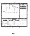
- FIG. 3 shows a screen representation of a touch screen for entering a desired one Bending profile.
- the entry is made by tapping the touch screen.
- computer 40 automatically draws that profile piece in between.
- the other bending points are in the same way 53, 54 and 55 and finally the second end point 56 entered.
- the start button 57 is pressed, whereupon the computer in searches a database for similar profiles.
- the data determined in the database the bending profiles 61, 62, and 63 that are similar to the desired bending profile shown graphically on screen 44.
- those can be selected from the database based on specified criteria Profiles are suggested that have the same or a similar number of bends have. However, profiles can also be proposed in which only the most distinctive bends correspond to those of the entered profile 50.
- the computer does not have anything similar to the entered profile 50 from the database Can suggest a bending profile, the one entered directly on the touch screen Profile 50 used and prepared for the bending process. This means that the bending sequence, which is stored in the database for each bending profile, is determined must become. This takes place automatically according to the present invention. A trial and error method is used for this.
- the bending sequences can be determined for any bending profile become.
- all bending steps can also be carried out be withdrawn. It may also be necessary to determine the bending order be to reclamp the sheet accordingly, which increases the number of Attempts increased accordingly.
- Bending tool 25, 27 for the upper beam 20 and / or the bending beam 22 Find an appropriately shaped one can also be tried Bending tool 25, 27 for the upper beam 20 and / or the bending beam 22 Find.
- the forms of bending tools are also stored in a database.
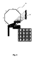
- Figure 4 shows a cross-sectional view through the work tool of a folding machine with which an octagonal profile was bent.
- the sheet 23 penetrates the upper cheek 20 in its bent state Case
- the computer 40 usually interprets it as a collision case.
- the specialist recognizes however, that such a profile despite this collision with the folding machine can be manufactured.
- the first part of the sheet that is bent rolls namely on the surface of the upper cheek 20 in a helical shape.
- the deformations can be achieved by simple approximations for a Material type and thickness, for example, linearly depending on the length of the sheet metal piece classified as permissible or impermissible from the collision point to the bending point become. If enough computing capacity is available, such Estimates are also made using complex bending equations.
Landscapes
- Engineering & Computer Science (AREA)
- Physics & Mathematics (AREA)
- Human Computer Interaction (AREA)
- Manufacturing & Machinery (AREA)
- General Physics & Mathematics (AREA)
- Automation & Control Theory (AREA)
- Mechanical Engineering (AREA)
- Geometry (AREA)
- Bending Of Plates, Rods, And Pipes (AREA)
Abstract
Description
- Figur 1
- eine schematische, perspektivische Darstellung einer computersteuerbaren Schwenkbiegemaschine;
- Figur 2
- eine Querschnittsansicht durch ein Arbeitswerkzeug mit eingelegtem, bearbeiteten Blech;
- Figur 3
- eine Ansicht auf eine erfindungsgemäße Eingabeeinheit zur Auswahl eines Biegeprofils; und
- Figur 4
- eine Querschnittsansicht durch ein Arbeitswerkzeug mit eingelegtem gebogenen Blech, das zu einer Kollision führt.
Claims (21)
- Schwenkbiegemaschine zum Biegen von Blechen mit
einer Steuereinrichtung (42), die über eine Eingabeeinheit bedienbar ist, und die
über eine Rechnereinheit (40) mit angeschlossenem Datenspeicher sowie eine Anzeigeeinheit (44) verfügt, wobei in die Eingabeeinrichtung ein gewünschtes Biegeprofil (50) eingebbar ist
dadurch gekennzeichnet, dass
durch die Rechnereinheit (40) eines oder mehrere einer Vielzahl von Biegeprofilen (61 bis 64) aus einer in dem Datenspeicher abgelegten Datenbank auf der Anzeigeeinheit (44) vorschlagbar ist/sind, das/die einem eingegebenen gewünschten Biegeprofil (50) nach vorgegebenen Kriterien am nächsten kommt/kommen, und
durch die Eingabeeinheit das vorgeschlagene oder eines der vorgeschlagenen Biegeprofile (61 bis 64) für die Steuereinrichtung (42) auswählbar ist. - Schwenkbiegemaschine nach Anspruch 1, wobei das vorgeschlagene Biegeprofil oder die vorgeschlagenen Biegeprofile (61 bis 64) neben dem eingegebenen Biegeprofil auf der Anzeigeeinheit (44) grafisch darstellbar ist/sind.
- Schwenkbiegemaschine nach Anspruch 1 oder 2, wobei die Eingabeeinheit einen Touch Screen umfasst.
- Schwenkbiegemaschine nach Anspruch 3, wobei die Endpunkte (51, 56) und Biegepunkte (52 bis 55) eines Biegeprofils durch Antippen des Touch Screens eingebbar sind.
- Schwenkbiegemaschine nach Anspruch 1 oder 2, wobei die Eingabeeinheit einen Scanner umfasst.
- Schwenkbiegemaschine nach einem der Ansprüche 1 bis 5, wobei mit der Rechnereinheit (40) eine Biegereihenfolge automatisch oder teilautomatisch unter Berücksichtigung der Geometrie der Schwenkbiegemaschine berechenbar ist.
- Schwenkbiegemaschine nach einem der Ansprüche 1 bis 6, wobei die Rechnereinheit (40) zum automatischen Vorschlagen jeweils eines Werkzeugs (25, 27) für eine Oberwange (20) und eine Biegewange (22) der Schwenkbiegemaschine ausgelegt ist.
- Verfahren zum Steuern einer Schwenkbiegemaschine durch
Eingeben eines gewünschten Biegeprofils (50) in eine Eingabeeinheit der Schwenkbiegemaschine,
gekennzeichnet durch
automatisches Vorschlagen eines oder mehrerer einer Vielzahl von Biegeprofilen (61 bis 64) aus einer Datenbank, das/die dem eingegebenen, gewünschten Biegeprofil (50) nach vorgegebenen Kriterien am nächsten kommt/kommen, und
Auswählen des vorgeschlagenen oder eines der vorgeschlagenen Biegeprofils/Biegeprofile mit Hilfe der Eingabeeinheit. - Verfahren nach Anspruch 8, wobei die Endpunkte (51, 56) und Biegepunkte (52, bis 55) eines Biegeprofils durch Antippen eines Touch Screens eingegeben werden.
- Verfahren nach Anspruch 8 oder 9, wobei eine Biegereihenfolge automatisch oder teilautomatisch unter Berücksichtigung der Geometrie der Schwenkbiegemaschine berechnet wird.
- Verfahren nach einem der Ansprüche 8 bis 10, wobei automatisch jeweils ein Werkzeug (25, 27) für eine Oberwange und eine Biegewange (22) der Schwenkbiegemaschine vorgeschlagen wird.
- Schwenkbiegemaschine zum Biegen von Blechen mit
einer Steuereinrichtung (42), die über eine Eingabeeinheit bedienbar ist, und die über eine Rechnereinheit (40) verfügt, wobei in die Eingabeeinheit ein gewünschtes Biegeprofil (50) eingebbar ist,
dadurch gekennzeichnet, dass
durch die Rechnereinheit (40) für ein eingegebenes, gewünschtes Biegeprofil (50) unter Berücksichtigung der Geometrie von Komponenten der Schwenkbiegemaschine eine Biegereihenfolge eines Blechs (23) berechenbar ist, so dass es zu keiner Kollision des Blechs (23) mit den Komponenten oder zu einer vorgebbaren zulässigen Verbiegung des zu bearbeitenden Blechs bei einer Kollision kommt. - Schwenkbiegemaschine nach Anspruch 12, wobei die Biegereihenfolge durch eine Versuch-Irrtum-Methode berechenbar ist.
- Schwenkbiegemaschine nach Anspruch 12 oder 13, wobei mit der Rechnereinheit (40) die Biegereihenfolge in einer Simulation derart festlegbar ist, dass für den Fall einer Kollision ein oder mehrere Biegeschritte zurückgenommen werden und die Biegung an einer anderen Stelle des Blechs (23) fortgesetzt wird.
- Schwenkbiegemaschine nach einem der Ansprüche 12 bis 14, wobei bei einer Kollision eine maximal zulässige Verbiegung in Abhängigkeit der Materialart, der Materialstärke und/oder der Länge eines bereits gebogenen Blechabschnitts halbautomatisch oder automatisch vorgebbar ist.
- Schwenkbiegemaschine nach einem der Ansprüche 12 bis 15, wobei Biegewerkzeuge (25, 27) der Schwenkbiegemaschine automatisch vorschlagbar sind.
- Verfahren zum Steuern einer Schwenkbiegemaschine durch
Eingeben eines gewünschten Biegeprofils (50) in eine Eingabeeinheit der Schwenkbiegemaschine,
gekennzeichnet durch
automatisches oder halbautomatisches Berechnen einer Biegereihenfolge eines Blechs (23) für das eingegebene gewünschte Biegeprofil (50) unter Berücksichtigung der Geometrie von Komponenten der Schwenkbiegemaschine, so dass es zu keiner Kollision des Blechs (23) mit den Komponenten oder zu einer vorgebbaren zulässigen Verbiegung des zu bearbeitenden Blechs bei einer Kollision kommt. - Verfahren nach Anspruch 17, wobei die Biegereihenfolge durch eine Versuch-Irrtum-Methode berechnet wird.
- Verfahren nach Anspruch 17 oder 18, wobei zur Festlegung der Biegereihenfolge diese simuliert wird und für den Fall einer Kollision ein oder mehrere Biegeschritte zurückgenommen und die Biegung an einer anderen Stelle des Blechs (23) fortgesetzt wird.
- Verfahren nach einem der Ansprüche 17 bis 19, wobei bei einer Kollision eine maximal zulässige Verbiegung in Abhängigkeit der Materialart, der Materialstärke und/oder der Länge eines bereits gebogenen Blechabschnitts halbautomatisch oder automatisch vorgegeben wird.
- Verfahren nach einem der Ansprüche 17 bis 20, wobei ein Biegewerkzeug (25, 27) der Schwenkbiegemaschine automatisch anhand eines auszuführenden Biegeprofils unter Berücksichtigung von Kollisionen und Verbiegungen vorgeschlagen wird.
Priority Applications (6)
| Application Number | Priority Date | Filing Date | Title |
|---|---|---|---|
| EP02023377A EP1411404B1 (de) | 2002-10-18 | 2002-10-18 | Schwenkbiegemaschine und entsprechendes Steuerverfahren |
| DE50207873T DE50207873D1 (de) | 2002-10-18 | 2002-10-18 | Schwenkbiegemaschine und entsprechendes Steuerverfahren |
| EP05024676A EP1640831B1 (de) | 2002-10-18 | 2002-10-18 | Schwenkbiegemaschine und entsprechendes Steuerverfahren mit automatischer Berechnung der Biegereihenfolge |
| AT05024676T ATE391311T1 (de) | 2002-10-18 | 2002-10-18 | Schwenkbiegemaschine und entsprechendes steuerverfahren mit automatischer berechnung der biegereihenfolge |
| DE50212039T DE50212039D1 (de) | 2002-10-18 | 2002-10-18 | Schwenkbiegemaschine und entsprechendes Steuerverfahren mit automatischer Berechnung der Biegereihenfolge |
| AT02023377T ATE336741T1 (de) | 2002-10-18 | 2002-10-18 | Schwenkbiegemaschine und entsprechendes steuerverfahren |
Applications Claiming Priority (1)
| Application Number | Priority Date | Filing Date | Title |
|---|---|---|---|
| EP02023377A EP1411404B1 (de) | 2002-10-18 | 2002-10-18 | Schwenkbiegemaschine und entsprechendes Steuerverfahren |
Related Child Applications (1)
| Application Number | Title | Priority Date | Filing Date |
|---|---|---|---|
| EP05024676A Division EP1640831B1 (de) | 2002-10-18 | 2002-10-18 | Schwenkbiegemaschine und entsprechendes Steuerverfahren mit automatischer Berechnung der Biegereihenfolge |
Publications (2)
| Publication Number | Publication Date |
|---|---|
| EP1411404A1 true EP1411404A1 (de) | 2004-04-21 |
| EP1411404B1 EP1411404B1 (de) | 2006-08-16 |
Family
ID=32039152
Family Applications (2)
| Application Number | Title | Priority Date | Filing Date |
|---|---|---|---|
| EP02023377A Expired - Lifetime EP1411404B1 (de) | 2002-10-18 | 2002-10-18 | Schwenkbiegemaschine und entsprechendes Steuerverfahren |
| EP05024676A Expired - Lifetime EP1640831B1 (de) | 2002-10-18 | 2002-10-18 | Schwenkbiegemaschine und entsprechendes Steuerverfahren mit automatischer Berechnung der Biegereihenfolge |
Family Applications After (1)
| Application Number | Title | Priority Date | Filing Date |
|---|---|---|---|
| EP05024676A Expired - Lifetime EP1640831B1 (de) | 2002-10-18 | 2002-10-18 | Schwenkbiegemaschine und entsprechendes Steuerverfahren mit automatischer Berechnung der Biegereihenfolge |
Country Status (3)
| Country | Link |
|---|---|
| EP (2) | EP1411404B1 (de) |
| AT (2) | ATE391311T1 (de) |
| DE (2) | DE50207873D1 (de) |
Cited By (2)
| Publication number | Priority date | Publication date | Assignee | Title |
|---|---|---|---|---|
| AT501465B1 (de) * | 2004-11-11 | 2006-09-15 | Duscher Nikolaus | Anordnung mit einer biegemaschine |
| WO2009103168A1 (en) * | 2008-02-20 | 2009-08-27 | Jorns Ag Lotzwil | Apparatus for bending metal sheets |
Citations (2)
| Publication number | Priority date | Publication date | Assignee | Title |
|---|---|---|---|---|
| EP0836896A2 (de) * | 1996-10-18 | 1998-04-22 | Schechtl Maschinenbau GmbH | Computersteuerbare Schwenkbiegemaschine |
| US5835684A (en) * | 1994-11-09 | 1998-11-10 | Amada Company, Ltd. | Method for planning/controlling robot motion |
Family Cites Families (1)
| Publication number | Priority date | Publication date | Assignee | Title |
|---|---|---|---|---|
| BR9205777A (pt) * | 1991-03-14 | 1994-04-26 | Lift Verkaufsgeraete Gmbh | Dispositivo de dobramento de chapas metálicas |
-
2002
- 2002-10-18 AT AT05024676T patent/ATE391311T1/de active
- 2002-10-18 EP EP02023377A patent/EP1411404B1/de not_active Expired - Lifetime
- 2002-10-18 EP EP05024676A patent/EP1640831B1/de not_active Expired - Lifetime
- 2002-10-18 DE DE50207873T patent/DE50207873D1/de not_active Expired - Lifetime
- 2002-10-18 DE DE50212039T patent/DE50212039D1/de not_active Expired - Lifetime
- 2002-10-18 AT AT02023377T patent/ATE336741T1/de active
Patent Citations (2)
| Publication number | Priority date | Publication date | Assignee | Title |
|---|---|---|---|---|
| US5835684A (en) * | 1994-11-09 | 1998-11-10 | Amada Company, Ltd. | Method for planning/controlling robot motion |
| EP0836896A2 (de) * | 1996-10-18 | 1998-04-22 | Schechtl Maschinenbau GmbH | Computersteuerbare Schwenkbiegemaschine |
Cited By (2)
| Publication number | Priority date | Publication date | Assignee | Title |
|---|---|---|---|---|
| AT501465B1 (de) * | 2004-11-11 | 2006-09-15 | Duscher Nikolaus | Anordnung mit einer biegemaschine |
| WO2009103168A1 (en) * | 2008-02-20 | 2009-08-27 | Jorns Ag Lotzwil | Apparatus for bending metal sheets |
Also Published As
| Publication number | Publication date |
|---|---|
| ATE391311T1 (de) | 2008-04-15 |
| DE50212039D1 (de) | 2008-05-15 |
| DE50207873D1 (de) | 2006-09-28 |
| EP1640831A1 (de) | 2006-03-29 |
| ATE336741T1 (de) | 2006-09-15 |
| EP1640831B1 (de) | 2008-04-02 |
| EP1411404B1 (de) | 2006-08-16 |
Similar Documents
| Publication | Publication Date | Title |
|---|---|---|
| DE3781887T2 (de) | Adaptivsteuerungssystem fuer hydraulische abkantpresse. | |
| AT401484B (de) | Verfahren und vorrichtung zum einstellen eines biegeprozesses sowie verfahren zum vorbereiten von biegedaten | |
| DE69735902T2 (de) | Verfahren zur herstellung eines werkstückes in einer biegepresse sowie biegepresse zur durchführung des verfahrens | |
| DE3852237T2 (de) | Verfahren zur eingabe der profildaten. | |
| DE102018009024B4 (de) | Einlerngerät zum Ausführen eines Einlernvorgangs für einen Roboter | |
| DE102018133551B4 (de) | Biegemaschine, Bearbeitungslinie und Verfahren zum Biegen | |
| DE112009005038B4 (de) | Numeriksteuerungs-Programmierverfahren, Vorrichtung dafür, und Programm, das einen Computer veranlasst, das Verfahren auszuführen | |
| DE3887422T2 (de) | Verfahren zum eintragen von informationen über das profil eines gegenstandes. | |
| DE102021117889A1 (de) | Zahnradbearbeitungsgerät und Bearbeitungsbedingungsbestimmungsvorrichtung | |
| DE3872612T2 (de) | Drehbank, versehen mit steuereinrichtung. | |
| EP0836896B1 (de) | Computersteuerbare Schwenkbiegemaschine | |
| CH646348A5 (de) | Verfahren und einrichtung zur numerischen prozess-steuerung einer biegepresse. | |
| EP1411404B1 (de) | Schwenkbiegemaschine und entsprechendes Steuerverfahren | |
| EP3778062B1 (de) | Verfahren zur formänderung eines plattenartigen werkstücks | |
| EP4076779B1 (de) | Biegemaschine mit einer kontrolleinrichtung | |
| WO2023180118A1 (de) | Verfahren zum betreiben einer werkzeugmaschine, sowie werkzeugmaschine | |
| DE112017004487T5 (de) | Maschine und Verfahren zum Fluidstrahlschneiden | |
| DE102006001496B4 (de) | System und Verfahren zur Bestimmung geometrischer Veränderungen eines Werkstücks | |
| DE102017208909A1 (de) | Verfahren zum Bestimmen von Materialeigenschaften eines Werkstücks durch Audioanalyse einer Werkstückbearbeitung sowie Stanzmaschine und Computerprogrammprodukt | |
| DE112018004141T5 (de) | Simulationsvorrichtung, pressensystem, simulationsverfahren, programm und speichermedium | |
| DE3925925C2 (de) | Biegeverfahren und Biegevorrichtung | |
| EP3482263B1 (de) | Automatische güteauswertung einer abfolge von bewegungsbefehlen | |
| DE3943814B4 (de) | Verfahren zum Bereitstellen von Biegedaten für eine Biegemaschine | |
| DE19840260B4 (de) | Sickenmaschine zum Sicken von Blechelementen | |
| DE4026119A1 (de) | Werkzeugmaschine mit mehreren bearbeitungskoepfen und verfahren zum steuern derselben |
Legal Events
| Date | Code | Title | Description |
|---|---|---|---|
| PUAI | Public reference made under article 153(3) epc to a published international application that has entered the european phase |
Free format text: ORIGINAL CODE: 0009012 |
|
| AK | Designated contracting states |
Kind code of ref document: A1 Designated state(s): AT BE BG CH CY CZ DE DK EE ES FI FR GB GR IE IT LI LU MC NL PT SE SK TR |
|
| AX | Request for extension of the european patent |
Extension state: AL LT LV MK RO SI |
|
| 17P | Request for examination filed |
Effective date: 20040908 |
|
| AKX | Designation fees paid |
Designated state(s): AT CH DE LI |
|
| GRAP | Despatch of communication of intention to grant a patent |
Free format text: ORIGINAL CODE: EPIDOSNIGR1 |
|
| GRAS | Grant fee paid |
Free format text: ORIGINAL CODE: EPIDOSNIGR3 |
|
| GRAA | (expected) grant |
Free format text: ORIGINAL CODE: 0009210 |
|
| AK | Designated contracting states |
Kind code of ref document: B1 Designated state(s): AT CH DE LI |
|
| REG | Reference to a national code |
Ref country code: CH Ref legal event code: EP |
|
| REF | Corresponds to: |
Ref document number: 50207873 Country of ref document: DE Date of ref document: 20060928 Kind code of ref document: P |
|
| REG | Reference to a national code |
Ref country code: CH Ref legal event code: NV Representative=s name: KELLER & PARTNER PATENTANWAELTE AG WINTERTHUR |
|
| PLBE | No opposition filed within time limit |
Free format text: ORIGINAL CODE: 0009261 |
|
| STAA | Information on the status of an ep patent application or granted ep patent |
Free format text: STATUS: NO OPPOSITION FILED WITHIN TIME LIMIT |
|
| 26N | No opposition filed |
Effective date: 20070518 |
|
| REG | Reference to a national code |
Ref country code: CH Ref legal event code: PCAR Free format text: NEW ADDRESS: EIGERSTRASSE 2 POSTFACH, 3000 BERN 14 (CH) |
|
| PGFP | Annual fee paid to national office [announced via postgrant information from national office to epo] |
Ref country code: DE Payment date: 20161031 Year of fee payment: 15 Ref country code: CH Payment date: 20161025 Year of fee payment: 15 |
|
| PGFP | Annual fee paid to national office [announced via postgrant information from national office to epo] |
Ref country code: AT Payment date: 20161024 Year of fee payment: 15 |
|
| REG | Reference to a national code |
Ref country code: DE Ref legal event code: R119 Ref document number: 50207873 Country of ref document: DE |
|
| REG | Reference to a national code |
Ref country code: CH Ref legal event code: PL |
|
| REG | Reference to a national code |
Ref country code: AT Ref legal event code: MM01 Ref document number: 336741 Country of ref document: AT Kind code of ref document: T Effective date: 20171018 |
|
| PG25 | Lapsed in a contracting state [announced via postgrant information from national office to epo] |
Ref country code: DE Free format text: LAPSE BECAUSE OF NON-PAYMENT OF DUE FEES Effective date: 20180501 Ref country code: LI Free format text: LAPSE BECAUSE OF NON-PAYMENT OF DUE FEES Effective date: 20171031 Ref country code: CH Free format text: LAPSE BECAUSE OF NON-PAYMENT OF DUE FEES Effective date: 20171031 |
|
| PG25 | Lapsed in a contracting state [announced via postgrant information from national office to epo] |
Ref country code: AT Free format text: LAPSE BECAUSE OF NON-PAYMENT OF DUE FEES Effective date: 20171018 |