EP1411252A2 - Schraube zur Verwendung bei aus Holz hergestellten Bauteilen - Google Patents
Schraube zur Verwendung bei aus Holz hergestellten Bauteilen Download PDFInfo
- Publication number
- EP1411252A2 EP1411252A2 EP03450161A EP03450161A EP1411252A2 EP 1411252 A2 EP1411252 A2 EP 1411252A2 EP 03450161 A EP03450161 A EP 03450161A EP 03450161 A EP03450161 A EP 03450161A EP 1411252 A2 EP1411252 A2 EP 1411252A2
- Authority
- EP
- European Patent Office
- Prior art keywords
- screw
- ribs
- shaft
- rotation
- thread
- Prior art date
- Legal status (The legal status is an assumption and is not a legal conclusion. Google has not performed a legal analysis and makes no representation as to the accuracy of the status listed.)
- Granted
Links
- 239000002023 wood Substances 0.000 title description 4
- 239000000463 material Substances 0.000 claims abstract description 10
- 238000006073 displacement reaction Methods 0.000 claims abstract description 5
- 241001494479 Pecora Species 0.000 description 2
- 230000001154 acute effect Effects 0.000 description 2
- 230000015572 biosynthetic process Effects 0.000 description 1
- 239000011093 chipboard Substances 0.000 description 1
- 239000000314 lubricant Substances 0.000 description 1
- 230000000630 rising effect Effects 0.000 description 1
Images

Classifications
-
- F—MECHANICAL ENGINEERING; LIGHTING; HEATING; WEAPONS; BLASTING
- F16—ENGINEERING ELEMENTS AND UNITS; GENERAL MEASURES FOR PRODUCING AND MAINTAINING EFFECTIVE FUNCTIONING OF MACHINES OR INSTALLATIONS; THERMAL INSULATION IN GENERAL
- F16B—DEVICES FOR FASTENING OR SECURING CONSTRUCTIONAL ELEMENTS OR MACHINE PARTS TOGETHER, e.g. NAILS, BOLTS, CIRCLIPS, CLAMPS, CLIPS OR WEDGES; JOINTS OR JOINTING
- F16B25/00—Screws that cut thread in the body into which they are screwed, e.g. wood screws
- F16B25/0036—Screws that cut thread in the body into which they are screwed, e.g. wood screws characterised by geometric details of the screw
- F16B25/0078—Screws that cut thread in the body into which they are screwed, e.g. wood screws characterised by geometric details of the screw with a shaft of non-circular cross-section or other special geometric features of the shaft
-
- F—MECHANICAL ENGINEERING; LIGHTING; HEATING; WEAPONS; BLASTING
- F16—ENGINEERING ELEMENTS AND UNITS; GENERAL MEASURES FOR PRODUCING AND MAINTAINING EFFECTIVE FUNCTIONING OF MACHINES OR INSTALLATIONS; THERMAL INSULATION IN GENERAL
- F16B—DEVICES FOR FASTENING OR SECURING CONSTRUCTIONAL ELEMENTS OR MACHINE PARTS TOGETHER, e.g. NAILS, BOLTS, CIRCLIPS, CLAMPS, CLIPS OR WEDGES; JOINTS OR JOINTING
- F16B25/00—Screws that cut thread in the body into which they are screwed, e.g. wood screws
- F16B25/001—Screws that cut thread in the body into which they are screwed, e.g. wood screws characterised by the material of the body into which the screw is screwed
- F16B25/0015—Screws that cut thread in the body into which they are screwed, e.g. wood screws characterised by the material of the body into which the screw is screwed the material being a soft organic material, e.g. wood or plastic
-
- F—MECHANICAL ENGINEERING; LIGHTING; HEATING; WEAPONS; BLASTING
- F16—ENGINEERING ELEMENTS AND UNITS; GENERAL MEASURES FOR PRODUCING AND MAINTAINING EFFECTIVE FUNCTIONING OF MACHINES OR INSTALLATIONS; THERMAL INSULATION IN GENERAL
- F16B—DEVICES FOR FASTENING OR SECURING CONSTRUCTIONAL ELEMENTS OR MACHINE PARTS TOGETHER, e.g. NAILS, BOLTS, CIRCLIPS, CLAMPS, CLIPS OR WEDGES; JOINTS OR JOINTING
- F16B25/00—Screws that cut thread in the body into which they are screwed, e.g. wood screws
- F16B25/10—Screws performing an additional function to thread-forming, e.g. drill screws or self-piercing screws
-
- F—MECHANICAL ENGINEERING; LIGHTING; HEATING; WEAPONS; BLASTING
- F16—ENGINEERING ELEMENTS AND UNITS; GENERAL MEASURES FOR PRODUCING AND MAINTAINING EFFECTIVE FUNCTIONING OF MACHINES OR INSTALLATIONS; THERMAL INSULATION IN GENERAL
- F16B—DEVICES FOR FASTENING OR SECURING CONSTRUCTIONAL ELEMENTS OR MACHINE PARTS TOGETHER, e.g. NAILS, BOLTS, CIRCLIPS, CLAMPS, CLIPS OR WEDGES; JOINTS OR JOINTING
- F16B35/00—Screw-bolts; Stay-bolts; Screw-threaded studs; Screws; Set screws
- F16B35/04—Screw-bolts; Stay-bolts; Screw-threaded studs; Screws; Set screws with specially-shaped head or shaft in order to fix the bolt on or in an object
- F16B35/041—Specially-shaped shafts
Definitions
- the subject invention relates to a screw for use in made of wood components with a shaft, which on one of his both ends with one actuator head and the other of its two Ends is formed with a conical tip and which further on the conical tip and in the adjoining area with a Screw thread is formed.
- the components for screwing in the screws are not pre-drilled.
- part of the shaft which is not threaded, with Forming friction edges, by which the screw hole is widened, whereby the friction between the unthreaded shaft and the screw hole is lowered.
- Part of the shaft which is provided with the thread, and the component so great a friction that an extension of the screws not possible is.
- An expansion of the screw hole e.g. in that this pre-drilled is therefore not effective, because this is the pull-out strength the screw would be reduced.
- the subject invention is therefore the object of a To provide a screw for use on wooden components, which due to the reduction of the screwing over compared to date known screws can be significantly extended.
- This is according to the invention achieved in that the shaft in his to the conical Tip adjacent area between the threads with transverse to the direction of rotation the screw extending ribs is formed, through which when screwing in the screw, the material is compressed by displacement becomes.
- the screw hole is characterized extended so that the applied material compacted by displacement which, although the between the material and the shaft of the Screw occurring friction is greatly reduced, however, the pull-out strength not lowered. This allows the lengths of the screws be greatly enlarged.
- the ribs extend at least approximately in the axial direction.
- the shaft over its circumference with the same distance from each other arranged ribs and formed with grooves located therebetween his.
- the individual ribs can be asymmetrical in cross-section Triangle be formed, wherein the lying in the direction of rotation flank is much less inclined than the edge away from the direction of rotation.
- the lying in the direction of rotation edge of the ribs opposite the tangent to the shaft is an angle of 20 ° to 40 ° and that of the Turning away from the direction of rotation include an angle of 50 ° to 70 °.
- the outer edge of the ribs may be rounded.
- the height of the ribs is 1% to 4% of the diameter of the threaded Be shaft part.
- the screw 1 shown in Figs. 1 and 2 for use in off Wood-made components, such as boards made of synthetic wood, e.g. Chipboard and Homogenholzplatten, has an actuating head 11, a to this subsequent sheep part 12, further a subsequent shaft part 13, which is formed with a thread 2, and a conical Tip 14 on.
- the shaft part 12 has a pressure gauge d1, which is slightly larger than the diameter d2 of the shaft part 13.
- the thread 2 has a diameter d3 which is larger than the diameter d1 of the shaft part 12.
- the shaft portion 13 In the region of the thread 2, which adjoins the conical tip 14 is the shaft portion 13 over a height of about three threads P at its Shell with a plurality of parallel to the axis of the screw 1 extending Formed ribs 3 or with grooves located between them.
- these ribs 3 have an asymmetrical triangular cross-section, wherein the lying in the screwing B of the screw 1 flank 31 with respect to the tangent to the lateral surface of the shaft 13 an acute angle ⁇ and lying away from the screw B Flank 32 opposite the tangent a larger acute angle ⁇ includes.
- the outer edge of the ribs 3 may be rounded.
- These ribs have a height which is 1% to 4% of the diameter of the threaded sheep portion 13.
- the purpose of the formation of the threaded shank part thirteenth with the ribs 3 is when screwing the screw 1 in the material the possibly pre-drilled borehole by displacement of the material expand, wherein the voltage applied to the screw 1 material compacts becomes. As a result, the between the shank of the screw 1 and the material occurring friction greatly reduced without thereby the pullout resistance the screw 1 is lowered. This allows the lengths the screws are greatly enlarged.
- Length of the wood screw up to 50 cm Diameter d1 of the unthreaded shaft part 5.77 mm to 5.85 mm Diameter d2 of the formed with a threaded shank part 5.0 mm to 5.3 mm Diameter d3 of the thread 7.7mm to 8.3mm Thread height P 3.6 mm Height f of the ribs 0.24 mm to 0.36 mm Angle ⁇ of the rising edge 20 ° to 40 ° Angle ⁇ of the falling edge 50 ° to 70 ° Radius Rf of the outer edge up to 0.5 mm
Abstract
Description
- Fig. 1
- eine erfindungsgemäße Schraube, in Draufsicht;
- Fig.2
- den Schnitt nach der Linie II - II der Fig. 1; und
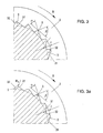
- Fig.3, Fig.3a
- das Detail A der Fig.2, in zwei gegenüber Fig. 2 vergrößerten Darstellungen.
Wie dies aus Fig.3a ersichtlich ist, kann die äußere Kante der Rippen 3 abgerundet sein. Diese Rippen weisen eine Höhe auf, welche 1 % bis 4% des Durchmessers des mit dem Gewinde versehen Schafteiles 13 beträgt.
| Länge der Holzschraube: | bis 50 cm |
| Durchmesser d1 des gewindefreien Schaftteiles | 5,77 mm bis 5,85 mm |
| Durchmesser d2 des mit einem Gewinde ausgebildeten Schaftteiles | 5,0 mm bis 5,3 mm |
| Durchmesser d3 des Gewindes | 7,7 mm bis 8,3 mm |
| Gewindehöhe P | 3,6 mm |
| Höhe f der Rippen | 0,24 mm bis 0,36 mm |
| Winkel α der ansteigenden Flanke | 20° bis 40° |
| Winkel β der abfallenden Flanke | 50° bis 70° |
| Radius Rf der Außenkante | bis 0.5 mm |
Claims (7)
- Schraube (1) mit einem Schaft, welcher an einem seiner beiden Enden mit einem Betätigungskopf (11) und am anderen seiner beiden Enden mit einer kegeligen Spitze (14) ausgebildet ist und welcher weiters an der kegeligen Spitze (14) und in dem an diese anschließenden Bereich mit einem Schraubgewinde (2) ausgebildet ist, dadurch gekennzeichnet, daß der Schaft in seinem an die kegelige Spitze (14) anliegenden Bereich zwischen den Gewindegängen (2) mit in quer zur Drehrichtung der Schraube verlaufenden Rippen (3) ausgebildet ist, durch welche beim Eindrehen der Schraube (1) das Material durch Verdrängung verdichtet wird.
- Schraube (1) nach Anspruch 1, dadurch gekennzeichnet, daß die Rippen (3) zumindest angenähert in Achsrichtung verlaufen.
- Schraube (1) nach einem der Ansprüche 1 und 2, dadurch gekennzeichnet, daß der Schaft über seinen Umfang mit im gleichen Abstand voneinander angeordneten Rippen (3) und mit dazwischen befindlichen Nuten ausgebildet ist.
- Schraube (1) nach einem der Ansprüche 1 bis 3, dadurch gekennzeichnet, daß die einzelnen Rippen (3) im Querschnitt als unsymmetrisches Dreieck ausgebildet sind, wobei die in Drehrichtung liegende Flanke (31) wesentlich geringer geneigt ist als die von der Drehrichtung abliegende Flanke (32).
- Schraube (1) nach Anspruch 4, dadurch gekennzeichnet, daß die in Drehrichtung liegende Flanke (31) der Rippen (3) gegenüber der Tangente an den Schaft einen Winkel von 20° bis 40° und die von der Drehrichtung abgewandte Flanke (32) einen Winkel von 50° bis 70° einschließt.
- Schraube (1) nach einem der Ansprüche 1 bis 5, dadurch gekennzeichnet, daß die äußere Kante der Rippen (3) abgerundet ist.
- Schraube (1) nach einem der Ansprüche 1 bis 6, dadurch gekennzeichnet, daß die Rippen (3) etwa 1 % bis 4 % des Durchmessers (d2) des mit dem Gewinde (2) versehenen Schaftteiles (13) beträgt.
Priority Applications (1)
| Application Number | Priority Date | Filing Date | Title |
|---|---|---|---|
| AT03450161T ATE331146T1 (de) | 2002-08-29 | 2003-07-03 | Schraube zur verwendung bei aus holz hergestellten bauteilen |
Applications Claiming Priority (2)
| Application Number | Priority Date | Filing Date | Title |
|---|---|---|---|
| AT0128902A AT412665B (de) | 2002-08-29 | 2002-08-29 | Schraube zur verwendung bei aus holz hergestellten bauteilen |
| AT12892002 | 2002-08-29 |
Publications (3)
| Publication Number | Publication Date |
|---|---|
| EP1411252A2 true EP1411252A2 (de) | 2004-04-21 |
| EP1411252A3 EP1411252A3 (de) | 2004-06-23 |
| EP1411252B1 EP1411252B1 (de) | 2006-06-21 |
Family
ID=32034592
Family Applications (1)
| Application Number | Title | Priority Date | Filing Date |
|---|---|---|---|
| EP03450161A Expired - Lifetime EP1411252B1 (de) | 2002-08-29 | 2003-07-03 | Schraube zur Verwendung bei aus Holz hergestellten Bauteilen |
Country Status (3)
| Country | Link |
|---|---|
| EP (1) | EP1411252B1 (de) |
| AT (2) | AT412665B (de) |
| DE (1) | DE50303923D1 (de) |
Cited By (19)
| Publication number | Priority date | Publication date | Assignee | Title |
|---|---|---|---|---|
| EP1873405A2 (de) * | 2006-06-29 | 2008-01-02 | SWG Schraubenwerk Gaisbach GmbH | Spanplattenschraube |
| DE102006031298A1 (de) * | 2006-06-29 | 2008-01-03 | Swg Schraubenwerk Gaisbach Gmbh | Spanplattenschraube |
| DE102007024240A1 (de) * | 2007-05-18 | 2008-11-20 | Swg Schraubenwerk Gaisbach Gmbh | Schraube |
| WO2012098139A1 (de) | 2011-01-21 | 2012-07-26 | Swg Schraubenwerk Gaisbach Gmbh | Spanplattenschraube |
| US20140294534A1 (en) * | 2013-03-26 | 2014-10-02 | Simpson Strong-Tie Company, Inc. | Variable thread knurl fastener |
| US8894339B2 (en) | 2005-12-02 | 2014-11-25 | Simpson Strong-Tie Company, Inc. | Variably threaded screw |
| EP2806174A1 (de) * | 2013-05-24 | 2014-11-26 | SPAX International GmbH & Co. KG | Schraubelement |
| DE102014205464A1 (de) | 2014-03-24 | 2015-09-24 | Schmid Schrauben Hainfeld Gmbh | Schraube |
| US9322422B2 (en) | 2012-07-23 | 2016-04-26 | Simpson Strong-Tie Company, Inc. | Fastener with drill pilot and reversed threaded regions |
| US9482258B2 (en) | 2012-05-10 | 2016-11-01 | Simpson Strong-Tie Company, Inc. | Fastener with multiple threaded regions |
| WO2016180661A1 (de) * | 2015-05-12 | 2016-11-17 | Adolf Würth Gmbh & Co.Kg | Schraube mit unterbrochenen schabekanten |
| US9523383B2 (en) | 2013-03-26 | 2016-12-20 | Simpson Strong-Tie Company, Inc. | Variable thread fastener |
| US9651079B2 (en) | 2013-03-21 | 2017-05-16 | Simpson Strong-Tie Company, Inc. | Fastener with prolate cross-section |
| DE102017108225A1 (de) | 2017-04-18 | 2018-10-18 | Adolf Würth Gmbh & Co Kg | Holzschraube mit bogenförmigem Überstand zwischen Gewindegängen |
| EP3401557A1 (de) * | 2017-05-12 | 2018-11-14 | Profix AG | Holzschraube |
| DE102017208284A1 (de) * | 2017-05-17 | 2018-11-22 | Schmid Schrauben Hainfeld Gmbh | Holzschraube für den konstruktiven Holzbau |
| TWI683966B (zh) * | 2018-09-26 | 2020-02-01 | 金美多實業有限公司 | 螺絲 |
| EP3677800A1 (de) | 2019-01-04 | 2020-07-08 | Kuo-Tai Hsu | Holzschraube |
| US11137012B2 (en) | 2019-02-21 | 2021-10-05 | Kuo Tai Hsu | Wood screw |
Families Citing this family (2)
| Publication number | Priority date | Publication date | Assignee | Title |
|---|---|---|---|---|
| TWM466982U (zh) | 2013-05-30 | 2013-12-01 | Shuenn Chang Fa Entpr Co Ltd | 螺絲 |
| DE102022211547A1 (de) | 2022-10-31 | 2024-05-02 | Helmut Wackenhut | Vorrichtung zum Verankern von Plattformen in Bäumen, Verfahren zum Verankern einer Plattform in einem Baum und Verfahren zur Herstellung einer Vorrichtung zum Verankern von Plattformen in Bäumen |
Citations (4)
| Publication number | Priority date | Publication date | Assignee | Title |
|---|---|---|---|---|
| US3937119A (en) * | 1974-12-23 | 1976-02-10 | Illinois Tool Works, Inc. | Masonry anchor device |
| US5273383A (en) * | 1991-04-04 | 1993-12-28 | Research Engineering & Manufacturing, Inc. | Threaded fastener for use in thermoplastics and roll die for producing same |
| US5827030A (en) * | 1995-09-06 | 1998-10-27 | A-Z Ausrustung Und Zubehor Gmbh & Co., Kg | Thread forming joining elements |
| US5895187A (en) * | 1996-09-23 | 1999-04-20 | Kuo-Tai; Hsu | Pilot screw |
Family Cites Families (1)
| Publication number | Priority date | Publication date | Assignee | Title |
|---|---|---|---|---|
| DE19525732A1 (de) * | 1995-07-14 | 1997-01-16 | Gaisbach Schraubenwerk Swg | Schraube |
-
2002
- 2002-08-29 AT AT0128902A patent/AT412665B/de not_active IP Right Cessation
-
2003
- 2003-07-03 AT AT03450161T patent/ATE331146T1/de not_active IP Right Cessation
- 2003-07-03 DE DE50303923T patent/DE50303923D1/de not_active Ceased
- 2003-07-03 EP EP03450161A patent/EP1411252B1/de not_active Expired - Lifetime
Patent Citations (4)
| Publication number | Priority date | Publication date | Assignee | Title |
|---|---|---|---|---|
| US3937119A (en) * | 1974-12-23 | 1976-02-10 | Illinois Tool Works, Inc. | Masonry anchor device |
| US5273383A (en) * | 1991-04-04 | 1993-12-28 | Research Engineering & Manufacturing, Inc. | Threaded fastener for use in thermoplastics and roll die for producing same |
| US5827030A (en) * | 1995-09-06 | 1998-10-27 | A-Z Ausrustung Und Zubehor Gmbh & Co., Kg | Thread forming joining elements |
| US5895187A (en) * | 1996-09-23 | 1999-04-20 | Kuo-Tai; Hsu | Pilot screw |
Cited By (36)
| Publication number | Priority date | Publication date | Assignee | Title |
|---|---|---|---|---|
| US8894339B2 (en) | 2005-12-02 | 2014-11-25 | Simpson Strong-Tie Company, Inc. | Variably threaded screw |
| DE102006031298A1 (de) * | 2006-06-29 | 2008-01-03 | Swg Schraubenwerk Gaisbach Gmbh | Spanplattenschraube |
| EP1873405A2 (de) * | 2006-06-29 | 2008-01-02 | SWG Schraubenwerk Gaisbach GmbH | Spanplattenschraube |
| US8480342B2 (en) | 2007-05-18 | 2013-07-09 | Wuerth International AG part interest | Screw |
| DE102007024240A1 (de) * | 2007-05-18 | 2008-11-20 | Swg Schraubenwerk Gaisbach Gmbh | Schraube |
| DE102011002962A1 (de) | 2011-01-21 | 2012-07-26 | Swg Schraubenwerk Gaisbach Gmbh | Spanplattenschraube |
| WO2012098139A1 (de) | 2011-01-21 | 2012-07-26 | Swg Schraubenwerk Gaisbach Gmbh | Spanplattenschraube |
| US10480559B2 (en) | 2012-05-10 | 2019-11-19 | Simpson Strong-Tie Company, Inc. | Fastener with head cutting structure |
| US9482258B2 (en) | 2012-05-10 | 2016-11-01 | Simpson Strong-Tie Company, Inc. | Fastener with multiple threaded regions |
| US9322422B2 (en) | 2012-07-23 | 2016-04-26 | Simpson Strong-Tie Company, Inc. | Fastener with drill pilot and reversed threaded regions |
| US9651079B2 (en) | 2013-03-21 | 2017-05-16 | Simpson Strong-Tie Company, Inc. | Fastener with prolate cross-section |
| US20140294534A1 (en) * | 2013-03-26 | 2014-10-02 | Simpson Strong-Tie Company, Inc. | Variable thread knurl fastener |
| WO2014160584A1 (en) * | 2013-03-26 | 2014-10-02 | Simpson Strong-Tie Company, Inc. | Variable thread knurl fastener |
| US11181138B2 (en) | 2013-03-26 | 2021-11-23 | Simpson Strong-Tie Company, Inc. | Variable thread knurl fastener |
| AU2019272060B2 (en) * | 2013-03-26 | 2021-11-18 | Simpson Strong-Tie Company | Variable thread knurl-fastener |
| US9523383B2 (en) | 2013-03-26 | 2016-12-20 | Simpson Strong-Tie Company, Inc. | Variable thread fastener |
| US9494179B2 (en) | 2013-05-24 | 2016-11-15 | Spax International Gmbh & Co. Kg | Schraubelement—screw element |
| JP2014228146A (ja) * | 2013-05-24 | 2014-12-08 | スパックス・インターナショナル・ゲー・エム・ベー・ハー・ウント・コー・カー・ゲーSpax International Gmbh & Co. Kg | ねじ要素 |
| RU2569769C1 (ru) * | 2013-05-24 | 2015-11-27 | СПАКС Интернациональ ГмбХ унд Ко. КГ | Винтовой элемент |
| EP2806174A1 (de) * | 2013-05-24 | 2014-11-26 | SPAX International GmbH & Co. KG | Schraubelement |
| AU2014202698B2 (en) * | 2013-05-24 | 2015-06-04 | Spax International Gmbh & Co. Kg | Screw element |
| CN104179770A (zh) * | 2013-05-24 | 2014-12-03 | Spax国际两合公司 | 螺钉件 |
| RU2569769C9 (ru) * | 2013-05-24 | 2016-03-27 | СПАКС Интернациональ ГмбХ унд Ко. КГ | Винтовой элемент |
| DE102014205464A1 (de) | 2014-03-24 | 2015-09-24 | Schmid Schrauben Hainfeld Gmbh | Schraube |
| DE102014205464B4 (de) | 2014-03-24 | 2020-07-16 | Schmid Schrauben Hainfeld Gmbh | Schraube |
| US10641310B2 (en) | 2015-05-12 | 2020-05-05 | Würth International Ag | Screw having discontinuous scraping edges |
| WO2016180661A1 (de) * | 2015-05-12 | 2016-11-17 | Adolf Würth Gmbh & Co.Kg | Schraube mit unterbrochenen schabekanten |
| EP3640487A1 (de) | 2017-04-18 | 2020-04-22 | Adolf Würth GmbH & Co. KG | Holzschraube mit bogenförmigem überstand zwischen gewindegängen |
| US10859107B2 (en) | 2017-04-18 | 2020-12-08 | Würth International Ag | Wood screw having a crescent-shaped protrusion between thread turns |
| DE102017108225A1 (de) | 2017-04-18 | 2018-10-18 | Adolf Würth Gmbh & Co Kg | Holzschraube mit bogenförmigem Überstand zwischen Gewindegängen |
| CH713769A1 (de) * | 2017-05-12 | 2018-11-15 | Profix Ag | Holzschraube. |
| EP3401557A1 (de) * | 2017-05-12 | 2018-11-14 | Profix AG | Holzschraube |
| DE102017208284A1 (de) * | 2017-05-17 | 2018-11-22 | Schmid Schrauben Hainfeld Gmbh | Holzschraube für den konstruktiven Holzbau |
| TWI683966B (zh) * | 2018-09-26 | 2020-02-01 | 金美多實業有限公司 | 螺絲 |
| EP3677800A1 (de) | 2019-01-04 | 2020-07-08 | Kuo-Tai Hsu | Holzschraube |
| US11137012B2 (en) | 2019-02-21 | 2021-10-05 | Kuo Tai Hsu | Wood screw |
Also Published As
| Publication number | Publication date |
|---|---|
| ATE331146T1 (de) | 2006-07-15 |
| EP1411252A3 (de) | 2004-06-23 |
| EP1411252B1 (de) | 2006-06-21 |
| DE50303923D1 (de) | 2006-08-03 |
| ATA12892002A (de) | 2004-10-15 |
| AT412665B (de) | 2005-05-25 |
Similar Documents
| Publication | Publication Date | Title |
|---|---|---|
| AT412665B (de) | Schraube zur verwendung bei aus holz hergestellten bauteilen | |
| EP1391617B1 (de) | Mit selbstklemmendem Gewinde versehene Schraube | |
| EP3359828B1 (de) | Gewindeformende schraube mit separater gewindespirale und unterschiedlichen teilflankenwinkeln | |
| DE4228727A1 (de) | Schraube, insbesondere für Hartholz | |
| DE3201846A1 (de) | Selbstformende schraube | |
| EP1001178A2 (de) | Gasbeton-Schraube | |
| EP1233194A2 (de) | Betonschraube | |
| DE4016724C2 (de) | ||
| DE4231546A1 (de) | Selbstfurchende Schraube | |
| EP1820978B1 (de) | Schraube zur Verwendung bei verformbaren Werkstoffen, wie Holz, Verbundwerkstoffen, Kunststoffen u. dgl. | |
| EP1574727A1 (de) | Selbstfurchende Schraube | |
| EP0108334B1 (de) | Schraube für Kunststoff-Spreizdübel | |
| EP0693162B1 (de) | Spreizdübel | |
| WO2018153635A1 (de) | Schraube | |
| EP2728209B1 (de) | Gewindeformende Schraube | |
| EP3004665A1 (de) | Gewindeformer und walzbacken | |
| EP2811181B1 (de) | Schraube | |
| EP1873405A2 (de) | Spanplattenschraube | |
| DD139744A5 (de) | Duebel | |
| DE102017002069A1 (de) | Einschraubdübel und Befestigungssystem mit einem Einschraubdübel | |
| WO2018210967A1 (de) | Holzschraube aus metall für den konstruktiven holzbau | |
| DE102006031299A1 (de) | Spanplattenschraube | |
| EP1611360A1 (de) | Pyramindendübel | |
| EP1650446A2 (de) | Verbindungselement mit Aussengewinde, insbesondere Spanplattenschraube | |
| EP1668261A1 (de) | Schraubenelement, insbesondere zur querzug- und/oder querdruckverstärkung von holzbauteilen |
Legal Events
| Date | Code | Title | Description |
|---|---|---|---|
| PUAI | Public reference made under article 153(3) epc to a published international application that has entered the european phase |
Free format text: ORIGINAL CODE: 0009012 |
|
| AK | Designated contracting states |
Kind code of ref document: A2 Designated state(s): AT BE BG CH CY CZ DE DK EE ES FI FR GB GR HU IE IT LI LU MC NL PT RO SE SI SK TR |
|
| AX | Request for extension of the european patent |
Extension state: AL LT LV MK |
|
| PUAL | Search report despatched |
Free format text: ORIGINAL CODE: 0009013 |
|
| AK | Designated contracting states |
Kind code of ref document: A3 Designated state(s): AT BE BG CH CY CZ DE DK EE ES FI FR GB GR HU IE IT LI LU MC NL PT RO SE SI SK TR |
|
| AX | Request for extension of the european patent |
Extension state: AL LT LV MK |
|
| 17P | Request for examination filed |
Effective date: 20041216 |
|
| AKX | Designation fees paid |
Designated state(s): AT BE BG CH CY CZ DE DK EE ES FI FR GB GR HU IE IT LI LU MC NL PT RO SE SI SK TR |
|
| GRAP | Despatch of communication of intention to grant a patent |
Free format text: ORIGINAL CODE: EPIDOSNIGR1 |
|
| GRAS | Grant fee paid |
Free format text: ORIGINAL CODE: EPIDOSNIGR3 |
|
| GRAA | (expected) grant |
Free format text: ORIGINAL CODE: 0009210 |
|
| AK | Designated contracting states |
Kind code of ref document: B1 Designated state(s): AT BE BG CH CY CZ DE DK EE ES FI FR GB GR HU IE IT LI LU MC NL PT RO SE SI SK TR |
|
| PG25 | Lapsed in a contracting state [announced via postgrant information from national office to epo] |
Ref country code: GB Free format text: LAPSE BECAUSE OF FAILURE TO SUBMIT A TRANSLATION OF THE DESCRIPTION OR TO PAY THE FEE WITHIN THE PRESCRIBED TIME-LIMIT Effective date: 20060621 Ref country code: SK Free format text: LAPSE BECAUSE OF FAILURE TO SUBMIT A TRANSLATION OF THE DESCRIPTION OR TO PAY THE FEE WITHIN THE PRESCRIBED TIME-LIMIT Effective date: 20060621 Ref country code: NL Free format text: LAPSE BECAUSE OF FAILURE TO SUBMIT A TRANSLATION OF THE DESCRIPTION OR TO PAY THE FEE WITHIN THE PRESCRIBED TIME-LIMIT Effective date: 20060621 Ref country code: IE Free format text: LAPSE BECAUSE OF FAILURE TO SUBMIT A TRANSLATION OF THE DESCRIPTION OR TO PAY THE FEE WITHIN THE PRESCRIBED TIME-LIMIT Effective date: 20060621 Ref country code: RO Free format text: LAPSE BECAUSE OF FAILURE TO SUBMIT A TRANSLATION OF THE DESCRIPTION OR TO PAY THE FEE WITHIN THE PRESCRIBED TIME-LIMIT Effective date: 20060621 Ref country code: SI Free format text: LAPSE BECAUSE OF FAILURE TO SUBMIT A TRANSLATION OF THE DESCRIPTION OR TO PAY THE FEE WITHIN THE PRESCRIBED TIME-LIMIT Effective date: 20060621 |
|
| REG | Reference to a national code |
Ref country code: GB Ref legal event code: FG4D Free format text: NOT ENGLISH |
|
| REG | Reference to a national code |
Ref country code: CH Ref legal event code: EP |
|
| REG | Reference to a national code |
Ref country code: IE Ref legal event code: FG4D Free format text: LANGUAGE OF EP DOCUMENT: GERMAN |
|
| PG25 | Lapsed in a contracting state [announced via postgrant information from national office to epo] |
Ref country code: MC Free format text: LAPSE BECAUSE OF NON-PAYMENT OF DUE FEES Effective date: 20060731 |
|
| REF | Corresponds to: |
Ref document number: 50303923 Country of ref document: DE Date of ref document: 20060803 Kind code of ref document: P |
|
| PG25 | Lapsed in a contracting state [announced via postgrant information from national office to epo] |
Ref country code: SE Free format text: LAPSE BECAUSE OF FAILURE TO SUBMIT A TRANSLATION OF THE DESCRIPTION OR TO PAY THE FEE WITHIN THE PRESCRIBED TIME-LIMIT Effective date: 20060921 Ref country code: DK Free format text: LAPSE BECAUSE OF FAILURE TO SUBMIT A TRANSLATION OF THE DESCRIPTION OR TO PAY THE FEE WITHIN THE PRESCRIBED TIME-LIMIT Effective date: 20060921 |
|
| REG | Reference to a national code |
Ref country code: CH Ref legal event code: NV Representative=s name: LUCHS & PARTNER PATENTANWAELTE |
|
| PG25 | Lapsed in a contracting state [announced via postgrant information from national office to epo] |
Ref country code: ES Free format text: LAPSE BECAUSE OF FAILURE TO SUBMIT A TRANSLATION OF THE DESCRIPTION OR TO PAY THE FEE WITHIN THE PRESCRIBED TIME-LIMIT Effective date: 20061002 |
|
| PG25 | Lapsed in a contracting state [announced via postgrant information from national office to epo] |
Ref country code: PT Free format text: LAPSE BECAUSE OF FAILURE TO SUBMIT A TRANSLATION OF THE DESCRIPTION OR TO PAY THE FEE WITHIN THE PRESCRIBED TIME-LIMIT Effective date: 20061121 |
|
| NLV1 | Nl: lapsed or annulled due to failure to fulfill the requirements of art. 29p and 29m of the patents act | ||
| REG | Reference to a national code |
Ref country code: IE Ref legal event code: FD4D |
|
| GBV | Gb: ep patent (uk) treated as always having been void in accordance with gb section 77(7)/1977 [no translation filed] |
Effective date: 20060621 |
|
| ET | Fr: translation filed | ||
| PLBE | No opposition filed within time limit |
Free format text: ORIGINAL CODE: 0009261 |
|
| STAA | Information on the status of an ep patent application or granted ep patent |
Free format text: STATUS: NO OPPOSITION FILED WITHIN TIME LIMIT |
|
| 26N | No opposition filed |
Effective date: 20070322 |
|
| PG25 | Lapsed in a contracting state [announced via postgrant information from national office to epo] |
Ref country code: GR Free format text: LAPSE BECAUSE OF FAILURE TO SUBMIT A TRANSLATION OF THE DESCRIPTION OR TO PAY THE FEE WITHIN THE PRESCRIBED TIME-LIMIT Effective date: 20060922 |
|
| PG25 | Lapsed in a contracting state [announced via postgrant information from national office to epo] |
Ref country code: BG Free format text: LAPSE BECAUSE OF FAILURE TO SUBMIT A TRANSLATION OF THE DESCRIPTION OR TO PAY THE FEE WITHIN THE PRESCRIBED TIME-LIMIT Effective date: 20060921 Ref country code: EE Free format text: LAPSE BECAUSE OF FAILURE TO SUBMIT A TRANSLATION OF THE DESCRIPTION OR TO PAY THE FEE WITHIN THE PRESCRIBED TIME-LIMIT Effective date: 20060621 |
|
| PG25 | Lapsed in a contracting state [announced via postgrant information from national office to epo] |
Ref country code: LU Free format text: LAPSE BECAUSE OF NON-PAYMENT OF DUE FEES Effective date: 20060703 Ref country code: HU Free format text: LAPSE BECAUSE OF FAILURE TO SUBMIT A TRANSLATION OF THE DESCRIPTION OR TO PAY THE FEE WITHIN THE PRESCRIBED TIME-LIMIT Effective date: 20061222 Ref country code: TR Free format text: LAPSE BECAUSE OF FAILURE TO SUBMIT A TRANSLATION OF THE DESCRIPTION OR TO PAY THE FEE WITHIN THE PRESCRIBED TIME-LIMIT Effective date: 20060621 |
|
| PG25 | Lapsed in a contracting state [announced via postgrant information from national office to epo] |
Ref country code: CY Free format text: LAPSE BECAUSE OF FAILURE TO SUBMIT A TRANSLATION OF THE DESCRIPTION OR TO PAY THE FEE WITHIN THE PRESCRIBED TIME-LIMIT Effective date: 20060621 |
|
| PGFP | Annual fee paid to national office [announced via postgrant information from national office to epo] |
Ref country code: CZ Payment date: 20081223 Year of fee payment: 7 |
|
| PGFP | Annual fee paid to national office [announced via postgrant information from national office to epo] |
Ref country code: BE Payment date: 20090629 Year of fee payment: 7 |
|
| PGFP | Annual fee paid to national office [announced via postgrant information from national office to epo] |
Ref country code: FR Payment date: 20090731 Year of fee payment: 7 |
|
| PGFP | Annual fee paid to national office [announced via postgrant information from national office to epo] |
Ref country code: AT Payment date: 20090729 Year of fee payment: 7 Ref country code: CH Payment date: 20090716 Year of fee payment: 7 Ref country code: DE Payment date: 20090907 Year of fee payment: 7 Ref country code: FI Payment date: 20090701 Year of fee payment: 7 |
|
| PGFP | Annual fee paid to national office [announced via postgrant information from national office to epo] |
Ref country code: IT Payment date: 20090710 Year of fee payment: 7 |
|
| PG25 | Lapsed in a contracting state [announced via postgrant information from national office to epo] |
Ref country code: DE Free format text: THE PATENT HAS BEEN ANNULLED BY A DECISION OF A NATIONAL AUTHORITY Effective date: 20091020 |
|
| BERE | Be: lapsed |
Owner name: *SCHMID SCHRAUBEN HAINFELD G.M.B.H. Effective date: 20100731 |
|
| PG25 | Lapsed in a contracting state [announced via postgrant information from national office to epo] |
Ref country code: CZ Free format text: LAPSE BECAUSE OF NON-PAYMENT OF DUE FEES Effective date: 20100703 |
|
| REG | Reference to a national code |
Ref country code: CH Ref legal event code: PL |
|
| REG | Reference to a national code |
Ref country code: FR Ref legal event code: ST Effective date: 20110331 |
|
| PG25 | Lapsed in a contracting state [announced via postgrant information from national office to epo] |
Ref country code: LI Free format text: LAPSE BECAUSE OF NON-PAYMENT OF DUE FEES Effective date: 20100731 Ref country code: CH Free format text: LAPSE BECAUSE OF NON-PAYMENT OF DUE FEES Effective date: 20100731 |
|
| PG25 | Lapsed in a contracting state [announced via postgrant information from national office to epo] |
Ref country code: IT Free format text: LAPSE BECAUSE OF NON-PAYMENT OF DUE FEES Effective date: 20100703 Ref country code: AT Free format text: LAPSE BECAUSE OF NON-PAYMENT OF DUE FEES Effective date: 20100703 Ref country code: FI Free format text: LAPSE BECAUSE OF NON-PAYMENT OF DUE FEES Effective date: 20100703 Ref country code: FR Free format text: LAPSE BECAUSE OF NON-PAYMENT OF DUE FEES Effective date: 20100802 |
|
| PG25 | Lapsed in a contracting state [announced via postgrant information from national office to epo] |
Ref country code: BE Free format text: LAPSE BECAUSE OF NON-PAYMENT OF DUE FEES Effective date: 20100731 |