EP1411243B1 - Soupape de commande pour un compresseur à capacité variable - Google Patents
Soupape de commande pour un compresseur à capacité variable Download PDFInfo
- Publication number
- EP1411243B1 EP1411243B1 EP03023513A EP03023513A EP1411243B1 EP 1411243 B1 EP1411243 B1 EP 1411243B1 EP 03023513 A EP03023513 A EP 03023513A EP 03023513 A EP03023513 A EP 03023513A EP 1411243 B1 EP1411243 B1 EP 1411243B1
- Authority
- EP
- European Patent Office
- Prior art keywords
- valve
- capacity control
- valve seat
- control valve
- crank chamber
- Prior art date
- Legal status (The legal status is an assumption and is not a legal conclusion. Google has not performed a legal analysis and makes no representation as to the accuracy of the status listed.)
- Expired - Lifetime
Links
Images


Classifications
-
- F—MECHANICAL ENGINEERING; LIGHTING; HEATING; WEAPONS; BLASTING
- F04—POSITIVE - DISPLACEMENT MACHINES FOR LIQUIDS; PUMPS FOR LIQUIDS OR ELASTIC FLUIDS
- F04B—POSITIVE-DISPLACEMENT MACHINES FOR LIQUIDS; PUMPS
- F04B27/00—Multi-cylinder pumps specially adapted for elastic fluids and characterised by number or arrangement of cylinders
- F04B27/08—Multi-cylinder pumps specially adapted for elastic fluids and characterised by number or arrangement of cylinders having cylinders coaxial with, or parallel or inclined to, main shaft axis
- F04B27/10—Multi-cylinder pumps specially adapted for elastic fluids and characterised by number or arrangement of cylinders having cylinders coaxial with, or parallel or inclined to, main shaft axis having stationary cylinders
- F04B27/1036—Component parts, details, e.g. sealings, lubrication
- F04B27/109—Lubrication
-
- F—MECHANICAL ENGINEERING; LIGHTING; HEATING; WEAPONS; BLASTING
- F04—POSITIVE - DISPLACEMENT MACHINES FOR LIQUIDS; PUMPS FOR LIQUIDS OR ELASTIC FLUIDS
- F04B—POSITIVE-DISPLACEMENT MACHINES FOR LIQUIDS; PUMPS
- F04B27/00—Multi-cylinder pumps specially adapted for elastic fluids and characterised by number or arrangement of cylinders
- F04B27/08—Multi-cylinder pumps specially adapted for elastic fluids and characterised by number or arrangement of cylinders having cylinders coaxial with, or parallel or inclined to, main shaft axis
- F04B27/14—Control
- F04B27/16—Control of pumps with stationary cylinders
- F04B27/18—Control of pumps with stationary cylinders by varying the relative positions of a swash plate and a cylinder block
- F04B27/1804—Controlled by crankcase pressure
- F04B2027/1822—Valve-controlled fluid connection
- F04B2027/1827—Valve-controlled fluid connection between crankcase and discharge chamber
-
- F—MECHANICAL ENGINEERING; LIGHTING; HEATING; WEAPONS; BLASTING
- F04—POSITIVE - DISPLACEMENT MACHINES FOR LIQUIDS; PUMPS FOR LIQUIDS OR ELASTIC FLUIDS
- F04B—POSITIVE-DISPLACEMENT MACHINES FOR LIQUIDS; PUMPS
- F04B27/00—Multi-cylinder pumps specially adapted for elastic fluids and characterised by number or arrangement of cylinders
- F04B27/08—Multi-cylinder pumps specially adapted for elastic fluids and characterised by number or arrangement of cylinders having cylinders coaxial with, or parallel or inclined to, main shaft axis
- F04B27/14—Control
- F04B27/16—Control of pumps with stationary cylinders
- F04B27/18—Control of pumps with stationary cylinders by varying the relative positions of a swash plate and a cylinder block
- F04B27/1804—Controlled by crankcase pressure
- F04B2027/1886—Open (not controlling) fluid passage
- F04B2027/189—Open (not controlling) fluid passage between crankcase and discharge chamber
Definitions
- This invention relates to a capacity control valve according to the preamble of claim 1, particularly for a variable displacement compressor in a refrigeration cycle of an automotive air conditioning system.
- variable displacement compressor In a known automotive air conditioning system, a variable displacement compressor is employed to obtain adequate cooling capacity without restriction by the rotational speed of the engine driving the compressor.
- the angle of a piston driving wobble plate is varied to change the delivery quantity of the compressor. The angle is continuously changed by introducing part of the compressed refrigerant into a gastight crank chamber and changing the pressure within the crank chamber.
- the amount of compressed refrigerant introduced into the crank chamber is controlled by a capacity control valve disposed, e.g., in a refrigerant flow path between a discharge chamber and the crank chamber.
- the valve holds the differential pressure between the discharge chamber pressure and a suction chamber pressure at a predetermined value which is externally set by a value of electric current applied to a solenoid of the valve.
- the amount of refrigerant discharged from the compressor is not influenced by variations of the engine speed.
- a variable displacement compressor is known in which a passage extending from a discharge chamber to a crank chamber via the capacity control valve is used as an oil return passage to efficiently introduce lubricating oil contained in the refrigerant into the compressor.
- Another known compressor employs an oil separator returning lubricating oil contained in the refrigerant into the crank chamber.
- the oil separator may be disposed in an oil return passage, for directly returning refrigerant from the discharge chamber to the crank chamber without introducing the oil burdened refrigerant into an external refrigerant circuit.
- JP-A-2002-213350 Another known compressor (JP-A-2002-213350) has an oil separator in an extraction passage between the crank chamber and the suction chamber. Separated lubricating oil is introduced into a passage extending from the capacity control valve to the crank chamber. Lubricating oil discharged from the discharge chamber then is returned directly and quickly to the crank chamber.
- variable displacement compressor in which the passage extending from the discharge chamber to the crank chamber via the capacity control valve is used as the oil return passage, it is possible to return lubricating oil to the crank chamber by a simple construction.
- the amount of returned lubricating oil is undesirably influenced by the adjusted state of the valve lift or opening degree of the capacity control valve.
- the valve When the valve is fully closed no oil is returned to the crank chamber, and hence sufficient lubrication of the compressor cannot be assured. This can cause seizure of the pistons and a stop of the operation of the compressor.
- the oil separator is used, the construction of the compressor is much more complicated, and the size of the compressor is undesirably increased by the oil separator.
- the present invention provides a capacity control valve according to claim 1.
- the communication passage communicating the discharge chamber and the crank chamber is additionally formed in the valve seat-forming member of the valve disposed between the discharge chamber side and the crank chamber side within the compressor, even when the valve element is seated on the valve seat for closing the capacity control valve, lubricating oil returning refrigerant nevertheless is introduced by a simple construction into the crank chamber.
- the capacity control valve can be manufactured at low costs and seldom suffers a breakdown.
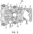
- the capacity control valve 100 of Fig. 1 is arranged in an intermediate portion of a refrigerant flow path extending from a discharge chamber to a crank chamber within a not shown variable displacement compressor e.g. for an automotive air conditioning system.
- the valve 100 controls the amount of refrigerant introduced into the crank chamber of the compressor to vary the discharge amount of the compressor.
- the capacity control valve 100 includes a spherical valve element 2 in the refrigerant flow path formed in an upper body 1.
- the flow path communicates at one end with the discharge chamber and at the other end with the crank chamber.
- the upper body 1 has an inner space communicating with the crank chamber, and contains a pressed-in valve seat-forming member 3.
- a strainer 4 covers the upper edge of the upper body 1. The inner space of the strainer 4 communicates with the discharge chamber.
- a valve hole 5 communicating the discharge chamber-side space and the crank chamber-side space is formed in the valve seat-forming member 3.
- the crank chamber-side end of the valve hole 5 defines a valve seat 5a for the valve element 2.
- a through hole 6 extends e.g. in parallel with the valve hole 5 in the valve seat-forming member 3. The through hole 6 as well connects the discharge chamber-side and the crank chamber-side spaces.
- the upper body 1 is press-fitted into an upper opening of a lower body 7.
- a piston rod 8 having the same diameter as the valve hole 5 (to be more precise, a portion corresponding to the valve seat 5a on which the valve element 2 is seated) is disposed axially movably along the axis of the upper body 1.
- One end of the piston rod 8 abuts at the valve element 2 on a side remote from the valve hole 5.
- the other end of the piston rod is exposed in an inner space of the lower body 7. That inner space of the lower body 7 communicates with a suction chamber of the variable displacement compressor.
- the piston rod 8 receives suction pressure Ps from the suction chamber at the exposed end.
- a lower opening of the lower body 7 is closed by a cap 9.
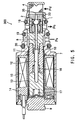
- the fixed core 10 has an upper central opening screwed onto a lower protruding portion of the upper body 1.
- a shaft 12 is axially movably inserted along the axis of the fixed core 10. One end of the shaft 12 abuts the end of the piston rod 8. The other end of the shaft 12 is fitted into a movable core 13.
- the shaft 12 and the movable core 13 slide axially in unison.
- the sleeve 11 is surrounded by a solenoid coil including a bobbin 14 and a magnet wire coil 15.
- a spring 16 is disposed between the movable core 13 and the fixed core 10.
- Another spring 17 is disposed between the end of the movable core 13 remote from the fixed core 10 and the bottom of the sleeve 11.
- An O ring 18 on the periphery of the upper body 1 seals between the portion communicating with the discharge chamber and receiving discharge pressure Pd and the portion communicating with the crank chamber and receiving pressure Pc when the capacity control valve 100 is mounted in the variable displacement compressor.
- An O ring 19 on the periphery of the lower body 7 seals between the portion receiving the pressure Pc from the crank chamber and the portion communicating with the suction chamber and receiving the suction pressure Ps.
- An O ring 20 on the periphery of the lower body 7 seals between the portion receiving the suction pressure Ps and the atmosphere.
- valve seat-forming member 3 in Fig. 2 is formed as to have the valve hole 5 and the through hole 6 e.g. extending in parallel with the valve hole 5. Both holes 5, 6 connect the discharge chamber-side and the crank chamber-side spaces.
- valve element 2 in Fig. 2 is held by a valve element-holding member 21 disposed in the lower opening of the valve seat-forming member 3 in a manner slidable along the axis of the piston rod 8, for causing the valve element 2 to open and close the valve hole 5.
- a spring 22 for urging the valve element element-holding member 21 in valve opening direction.
- the discharge pressure Pd introduced from the discharge chamber acts leftward on the valve element 2.
- the suction pressure Ps from the suction chamber acts rightward on the piston rod 8.
- An effective pressure-receiving area of the valve element 2 on which the discharge pressure Pd is received is equal to the pressure-receiving area of the piston rod 8 on which the suction passage Ps is received. Therefore, the valve element 2 controlling the flow rate of refrigerant from the discharge chamber to the crank chamber forms a differential pressure valve that senses the differential pressure between the discharge pressure Pd and the suction pressure Ps and operates in response thereto.
- the movable core 13 When a maximum control current is supplied to the magnet wire coil 15, the movable core 13 is attracted by the fixed core 10 and moves rightward.
- the capacity control valve 100 is fully closed.
- refrigerant in the crank chamber By maintaining communication between the suction chamber side and the crank chamber side via a not shown orifice only refrigerant in the crank chamber is allowed to flow into the suction chamber via the orifice, whereby the pressure Pc within the crank chamber is lowered to a value close to the suction pressure Ps within the suction chamber.
- the difference between the pressures applied to the opposite end faces of each piston is maximized, whereby the wobble plate is inclined at such an inclination angle that maximizes the length of the piston stroke, thus controlling the variable displacement compressor to a maximum capacity operation.
- the capacity control valve 100 senses the differential pressure between the discharge pressure Pd and the suction pressure Ps, and controls the flow rate of refrigerant flowing from the discharge chamber to the crank chamber such that the differential pressure is maintained at a differential pressure corresponding to the value set by the current supplied to the solenoid section.
- the refrigerant flowing in the capacity control valve 100 and in the variable displacement compressor contains lubricating oil for lubrication of the inside of the variable displacement compressor.
- the flow path between the discharge chamber and the crank chamber via the capacity control valve 100 also functions as an oil return passage for returning the lubricating oil.
- Compressed refrigerant discharged from the discharge chamber returns to the crank chamber through the short route without passing through an external refrigerant circuit, which enables the lubricating oil to efficiently internally circulate from the discharge chamber to the crank chamber, and then from the crank chamber to the suction chamber via the mentioned orifice.
- an additional communication passage which allows refrigerant to flow to the crank chamber when the capacity control valve 100 is closed is formed in the valve seat-forming member 3, to thereby maintain oil circulation even when the valve element 2 is seated on the valve seat 5a.
- the additional communication passage is not controlled by the valve element 2.
- the valve seat-forming member 3 has the through hole 6 as this communication passage.
- the through hole 6 extends e.g. in parallel with the valve hole 5 in the valve seat-forming member 3, for communicating between the discharge chamber-side space and the crank chamber-side space.
- the through hole 6 is e.g. circular in cross section, and its cross-sectional area may be smaller than the cross-section of the valve hole 5.
- the valve hole 5 has a diameter of e.g.
- the through hole 6 has a diameter of approximately 0.1 mm to 0.3 mm, namely with a view to reducing influence on the compression performance of the compressor, of ensuring sufficient flow of lubricating oil from the discharge chamber side to the crank chamber side, to facilitate machining, and to easily maintain the required accuracy.
- the through hole 6 establishes a refrigerant flow path from the discharge chamber side to the crank chamber side so as to efficiently return sufficient lubricating oil into the variable displacement compressor even when the capacity control valve 100 is closed.
- the construction described above can be suitably employed particularly when a CO 2 refrigerant difficult to mix with lubricating oil is used.
- the needed circulation of lubricating oil can be easily ensured without using a complicated device, such as an oil separator, but simply by forming a permanently open hole through the valve seat-forming member 3.
- the capacity control valve 100 may have a small size and a low failure rate, at low manufacturing costs.
- the capacity control valve 200 in Figs 3 and 4 is distinguished from the first embodiment by the shape of the additional communication passage formed in the valve seat-forming member 23 disposed between the inner space of the strainer 4 communicating with the discharge chamber and the inner space of the upper body 1 communicating with the crank chamber.
- the valve seat-forming member 23 has a valve hole 25 communicating the discharge chamber-side and the crank chamber-side spaces.
- a crank chamber-side end of the valve hole 25 functions as a valve seat 25a for the valve element 2.
- the valve seat 25a has at least one nick 25b formed on one portion of its peripheral edge.
- valve element 2 is seated and held in contact with the valve seat 5a but not in contact with the nick 25b. Hence a gap is created by the nick 25b allowing oil containing refrigerant to flow past the valve seat 25a toward the crank chamber side even when the valve element 2 is seated on the valve seat 25a.
- the nick 25b has a size small enough to minimize influence on the compression performance of the variable displacement compressor and to allow required machining accuracy to be easily achieved, similarly to the communication passage in the first embodiment.
- the valve hole 25 has a diameter of approximately 1.0 mm to 1.2 mm, it is desirable to form a nick having an equivalent to the opening area corresponding to that of a drilled hole having a diameter of approximately 0.1 mm to 0.3 mm, as described for the first embodiment.
- the capacity control valve 300 in Figs. 5 and 6 is distinguished from the first and second embodiments by the shape of the additional communication passage formed in the valve seat-forming member 33 disposed between the discharge chamber-side and the crank chamber-side spaces of the valve.
- the valve seat-forming member 33 has a valve hole 35 communicating the discharge chamber-side and the crank chamber-side spaces.
- a crank chamber-side end of the valve hole 35 functions as the valve seat 35a for the valve element 2.
- the valve seat-forming member 33 is press-fitted in the upper opening of the upper body 1.
- An inner wall of the upper opening of the upper body 1 and an upper outer peripheral surface of the valve seat-forming member 33 are in contact with each other.
- An e.g. axially extending communication groove 35b is formed on one portion of the upper outer peripheral surface of the valve seat-forming member 33.
- the communication groove 35b in Fig. 6 extends between the space communicating with the discharge chamber and the space communicating with the crank chamber.
- the communication groove 35b e.g. may have a V shape or a curved shape in cross section. It is desirable that the cross-sectional area of a gap created between the communication groove 35b and the inner wall of the upper body 1 is small enough to minimize influence on the compression performance of the variable displacement compressor and allow required machining accuracy to be easily achieved, similarly to the communication passages in the above first and second embodiments.
- valve seat-forming member 33 After forming the valve seat-forming member 33, it is possible to form the communication groove 35b on the upper outer peripheral surface of the valve seat-forming member by the same method as it is used for forming a scribe line, and hence manufacturing efficiency is higher than in the above first and second embodiments.
- the inventive concept may be employed in any capacity control valve that has a valve element in a flow channel from a discharge chamber side to a crank chamber side. This allows to reduce the size of the capacity control valve and of the compressor provided with the capacity control valve, and contributes to reduction of the manufacturing costs of these components.
- the capacity control valve performs control of the differential pressure between the discharge pressure Pd within the discharge chamber and the suction pressure Ps within the suction chamber.
- the same concept also may be applied to a capacity control valve that performs control such that the suction pressure Ps is held constant.
- any valve element may be used having a shape other than the spherical shape as shown.
Claims (7)
- Vanne de régulation de capacité (100, 200, 300) pour un compresseur à cylindrée variable, destinée à réguler une quantité d'agent réfrigérant à introduire depuis une chambre de décharge dans un carter moteur du compresseur, pour ainsi modifier une capacité d'agent réfrigérant déchargé par le compresseur,
caractérisée en ce qu'un passage de communication supplémentaire est formé dans un élément formant un siège de vanne (3, 23, 33) situé dans un passage d'agent réfrigérant faisant communiquer la chambre de décharge et le carter moteur afin de relier constamment un côté de la chambre de décharge et un côté du carter moteur même lorsque la vanne de régulation de capacité (100, 200, 300) est à l'état complètement fermé. - Vanne de régulation de capacité selon la revendication 1, caractérisée en ce que le passage de communication est un trou débouchant (6) formé à travers l'élément formant un siège de vanne (3), de préférence en parallèle avec un trou de vanne (5).
- Vanne de régulation de capacité selon la revendication 1, caractérisée en ce que le passage de communication est une encoche (25b) formée sur une partie d'un siège de vanne (25a) de sorte qu'un jeu se forme lorsque la vanne est fermée.
- Vanne de régulation de capacité selon la revendication 1, caractérisée par un élément de retenue (1) ayant une ouverture d'emmanchement à force communicant entre le côté de la chambre de décharge et le côté du carter moteur, et maintenant l'élément formant un siège de vanne (33) emmanché à force dans l'ouverture d'emmanchement à force, et
par le passage de communication supplémentaire formé par au moins une rainure (35b) formée sur une surface périphérique externe de l'élément formant un siège de vanne (33) de manière à s'étendre du côté de la chambre de décharge au côté du carter moteur. - Vanne de régulation de capacité selon la revendication 1, caractérisée par un élément de vanne (2) disposé pour ouvrir et fermer le passage d'agent réfrigérant, de sorte que l'élément de vanne (2) peut être placé sur un siège de vanne (5a, 25a, 35a) formé sur l'élément formant un siège de vanne (3, 23, 33), à partir du côté du carter moteur, et
une section de solénoïde pour appliquer une force magnétique axiale à l'élément de vanne (2). - Vanne de régulation de capacité selon la revendication 5, caractérisée par une tige de piston (8) située de manière coaxiale par rapport à l'élément de vanne (2) et ayant l'une de ses extrémités adjacente à l'élément de vanne et l'autre extrémité comportant une zone de réception de pression aussi grande qu'une zone de réception de pression efficace de l'élément de vanne (2), la tige de piston (8) recevant une pression d'aspiration (Ps) provenant d'une chambre d'aspiration située sur l'autre extrémité de celle-ci.
- Vanne de régulation de capacité selon la revendication 1, caractérisée en ce que la vanne de régulation de capacité comprend un siège de vanne (5a, 25a, 35a) dans un passage d'agent réfrigérant entre la chambre de décharge et le carter moteur du compresseur, et un élément de vanne (2) qui est mobile par rapport au siège de vanne entre un état fermé et des états d'ouverture de degrés d'ouverture variables dont un état complètement ouvert,
en ce que, en plus du siège de vanne (5a, 25a, 35a), au moins un passage de communication ouvert de façon permanente (6, 25b, 35b) court-circuite le siège de vanne (5a, 25a, 35a) entre un côté de la chambre de décharge et un côté du carter moteur du siège de vanne, et en ce que la section du passage de communication est plus petite que la section d'écoulement libre entre l'élément de vanne (2) et le siège de vanne (25a, 5a, 35a) à l'état complètement ouvert.
Applications Claiming Priority (2)
| Application Number | Priority Date | Filing Date | Title |
|---|---|---|---|
| JP2002303998 | 2002-10-18 | ||
| JP2002303998A JP2004137980A (ja) | 2002-10-18 | 2002-10-18 | 可変容量圧縮機用容量制御弁 |
Publications (2)
| Publication Number | Publication Date |
|---|---|
| EP1411243A1 EP1411243A1 (fr) | 2004-04-21 |
| EP1411243B1 true EP1411243B1 (fr) | 2005-10-05 |
Family
ID=32040855
Family Applications (1)
| Application Number | Title | Priority Date | Filing Date |
|---|---|---|---|
| EP03023513A Expired - Lifetime EP1411243B1 (fr) | 2002-10-18 | 2003-10-15 | Soupape de commande pour un compresseur à capacité variable |
Country Status (4)
| Country | Link |
|---|---|
| US (1) | US20040074245A1 (fr) |
| EP (1) | EP1411243B1 (fr) |
| JP (1) | JP2004137980A (fr) |
| DE (1) | DE60301775T2 (fr) |
Families Citing this family (12)
| Publication number | Priority date | Publication date | Assignee | Title |
|---|---|---|---|---|
| JP4152674B2 (ja) * | 2002-06-04 | 2008-09-17 | 株式会社テージーケー | 可変容量圧縮機用容量制御弁 |
| JP2006057506A (ja) * | 2004-08-19 | 2006-03-02 | Tgk Co Ltd | 可変容量圧縮機用制御弁 |
| JP4572273B2 (ja) * | 2005-08-17 | 2010-11-04 | 株式会社テージーケー | 可変容量圧縮機用制御弁 |
| JP2007154718A (ja) * | 2005-12-02 | 2007-06-21 | Tgk Co Ltd | 可変容量圧縮機用制御弁 |
| EP1995460B1 (fr) * | 2006-03-15 | 2014-07-30 | Eagle Industry Co., Ltd. | Soupape de regulation de capacite |
| KR100873369B1 (ko) * | 2007-12-28 | 2008-12-10 | 학교법인 두원학원 | 왕복동식 압축기의 제어밸브 |
| KR100933264B1 (ko) | 2008-08-06 | 2009-12-22 | 학교법인 두원학원 | 용량가변형 압축기의 용량제어밸브 |
| DE102012011519A1 (de) * | 2012-06-08 | 2013-12-12 | Yack SAS | Klimaanlage |
| JP6340661B2 (ja) * | 2014-02-27 | 2018-06-13 | 株式会社テージーケー | 可変容量圧縮機用制御弁 |
| JP6281047B2 (ja) * | 2014-04-22 | 2018-02-21 | 株式会社テージーケー | 可変容量圧縮機用制御弁 |
| JP2016014334A (ja) * | 2014-07-01 | 2016-01-28 | 株式会社テージーケー | 可変容量圧縮機用制御弁 |
| JP2021021330A (ja) * | 2019-07-24 | 2021-02-18 | サンデン・オートモーティブコンポーネント株式会社 | 可変容量圧縮機の制御弁 |
Family Cites Families (8)
| Publication number | Priority date | Publication date | Assignee | Title |
|---|---|---|---|---|
| JPH10196540A (ja) * | 1997-01-10 | 1998-07-31 | Toyota Autom Loom Works Ltd | 圧縮機 |
| JP2000045940A (ja) * | 1998-07-27 | 2000-02-15 | Toyota Autom Loom Works Ltd | 可変容量型圧縮機 |
| JP2001289164A (ja) * | 2000-04-07 | 2001-10-19 | Toyota Autom Loom Works Ltd | 可変容量圧縮機及びそれへの潤滑油供給方法 |
| JP3735512B2 (ja) * | 2000-05-10 | 2006-01-18 | 株式会社豊田自動織機 | 容量可変型圧縮機の制御弁 |
| JP2001355570A (ja) * | 2000-06-14 | 2001-12-26 | Toyota Industries Corp | ピストン式容量可変型圧縮機 |
| ATE367525T1 (de) * | 2000-07-06 | 2007-08-15 | Ixetic Mac Gmbh | Sicherheitseinrichtung für klimakompressor |
| JP4399994B2 (ja) * | 2000-11-17 | 2010-01-20 | 株式会社豊田自動織機 | 容量可変型圧縮機 |
| US6732541B2 (en) * | 2002-05-03 | 2004-05-11 | Delphi Technologies, Inc. | Electrically operated compressor capacity control system with integral pressure sensors |
-
2002
- 2002-10-18 JP JP2002303998A patent/JP2004137980A/ja active Pending
-
2003
- 2003-09-30 US US10/673,494 patent/US20040074245A1/en not_active Abandoned
- 2003-10-15 DE DE60301775T patent/DE60301775T2/de not_active Expired - Fee Related
- 2003-10-15 EP EP03023513A patent/EP1411243B1/fr not_active Expired - Lifetime
Also Published As
| Publication number | Publication date |
|---|---|
| DE60301775D1 (de) | 2006-02-16 |
| EP1411243A1 (fr) | 2004-04-21 |
| DE60301775T2 (de) | 2006-05-18 |
| JP2004137980A (ja) | 2004-05-13 |
| US20040074245A1 (en) | 2004-04-22 |
Similar Documents
| Publication | Publication Date | Title |
|---|---|---|
| CN100378325C (zh) | 用于可变容积式压缩机的控制阀 | |
| KR970001758B1 (ko) | 전자식 제어밸브 | |
| EP1411243B1 (fr) | Soupape de commande pour un compresseur à capacité variable | |
| EP1281868B1 (fr) | Soupape de contrôle de capacité | |
| US9556862B2 (en) | Control valve for variable displacement compressor | |
| EP1602828A2 (fr) | Soupape de contrôle pour un compresseur à capacité variable | |
| KR20060086883A (ko) | 가변 용량형 압축기 | |
| CN100396916C (zh) | 可变容量压缩机的控制阀 | |
| US7077380B2 (en) | Capacity control drive | |
| KR20060050534A (ko) | 가변 용량 압축기용 제어 밸브 | |
| EP1363023A2 (fr) | Soupape de contrôle pour un compresseur à capacité variable | |
| EP1512871A1 (fr) | Soupape de contrôle pour un compresseur à capacité variable | |
| EP1369583A2 (fr) | Soupape de commande pour un compresseur à capacité variable | |
| US20060150649A1 (en) | Control valve for variable displacement compressor | |
| KR20030069040A (ko) | 용량가변형 압축기의 제어장치 | |
| JPWO2019142931A1 (ja) | 容量制御弁 | |
| US20060053812A1 (en) | Control valve for variable displacement compressor | |
| KR20200110134A (ko) | 가변용량형 압축기용 제어 밸브 | |
| EP2975266B1 (fr) | Soupape de contrôle pour compresseur à déplacement variable | |
| US11149722B2 (en) | Variable displacement refrigerant compressor having a control valve adapted to adjust an opening degree of a pressure supply passage and a switching valve in the pressure supply passage closer to a controlled pressure chamber than the control valve and switching between a first state and a second state | |
| WO2019139132A1 (fr) | Compresseur à capacité variable | |
| JP2006125292A (ja) | 可変容量圧縮機用制御弁 | |
| JP2021017875A (ja) | 可変容量圧縮機 |
Legal Events
| Date | Code | Title | Description |
|---|---|---|---|
| PUAI | Public reference made under article 153(3) epc to a published international application that has entered the european phase |
Free format text: ORIGINAL CODE: 0009012 |
|
| AK | Designated contracting states |
Kind code of ref document: A1 Designated state(s): AT BE BG CH CY CZ DE DK EE ES FI FR GB GR HU IE IT LI LU MC NL PT RO SE SI SK TR |
|
| AX | Request for extension of the european patent |
Extension state: AL LT LV MK |
|
| 17P | Request for examination filed |
Effective date: 20040325 |
|
| 17Q | First examination report despatched |
Effective date: 20041022 |
|
| AKX | Designation fees paid |
Designated state(s): DE ES FR GB IT |
|
| GRAP | Despatch of communication of intention to grant a patent |
Free format text: ORIGINAL CODE: EPIDOSNIGR1 |
|
| GRAS | Grant fee paid |
Free format text: ORIGINAL CODE: EPIDOSNIGR3 |
|
| GRAA | (expected) grant |
Free format text: ORIGINAL CODE: 0009210 |
|
| AK | Designated contracting states |
Kind code of ref document: B1 Designated state(s): DE ES FR GB IT |
|
| PG25 | Lapsed in a contracting state [announced via postgrant information from national office to epo] |
Ref country code: IT Free format text: LAPSE BECAUSE OF FAILURE TO SUBMIT A TRANSLATION OF THE DESCRIPTION OR TO PAY THE FEE WITHIN THE PRESCRIBED TIME-LIMIT;WARNING: LAPSES OF ITALIAN PATENTS WITH EFFECTIVE DATE BEFORE 2007 MAY HAVE OCCURRED AT ANY TIME BEFORE 2007. THE CORRECT EFFECTIVE DATE MAY BE DIFFERENT FROM THE ONE RECORDED. Effective date: 20051005 |
|
| REG | Reference to a national code |
Ref country code: GB Ref legal event code: FG4D |
|
| PG25 | Lapsed in a contracting state [announced via postgrant information from national office to epo] |
Ref country code: ES Free format text: LAPSE BECAUSE OF FAILURE TO SUBMIT A TRANSLATION OF THE DESCRIPTION OR TO PAY THE FEE WITHIN THE PRESCRIBED TIME-LIMIT Effective date: 20060116 |
|
| REF | Corresponds to: |
Ref document number: 60301775 Country of ref document: DE Date of ref document: 20060216 Kind code of ref document: P |
|
| ET | Fr: translation filed | ||
| PLBE | No opposition filed within time limit |
Free format text: ORIGINAL CODE: 0009261 |
|
| STAA | Information on the status of an ep patent application or granted ep patent |
Free format text: STATUS: NO OPPOSITION FILED WITHIN TIME LIMIT |
|
| 26N | No opposition filed |
Effective date: 20060706 |
|
| GBPC | Gb: european patent ceased through non-payment of renewal fee |
Effective date: 20071015 |
|
| PG25 | Lapsed in a contracting state [announced via postgrant information from national office to epo] |
Ref country code: GB Free format text: LAPSE BECAUSE OF NON-PAYMENT OF DUE FEES Effective date: 20071015 |
|
| PGFP | Annual fee paid to national office [announced via postgrant information from national office to epo] |
Ref country code: DE Payment date: 20081127 Year of fee payment: 6 |
|
| PGFP | Annual fee paid to national office [announced via postgrant information from national office to epo] |
Ref country code: FR Payment date: 20081024 Year of fee payment: 6 |
|
| REG | Reference to a national code |
Ref country code: FR Ref legal event code: ST Effective date: 20100630 |
|
| PG25 | Lapsed in a contracting state [announced via postgrant information from national office to epo] |
Ref country code: FR Free format text: LAPSE BECAUSE OF NON-PAYMENT OF DUE FEES Effective date: 20091102 Ref country code: DE Free format text: LAPSE BECAUSE OF NON-PAYMENT OF DUE FEES Effective date: 20100501 |