EP1411212A2 - Elektromagnetische Ventiltriebvorrichtung mit verdrehgesicherter Neutrallagenverstellschraube - Google Patents
Elektromagnetische Ventiltriebvorrichtung mit verdrehgesicherter Neutrallagenverstellschraube Download PDFInfo
- Publication number
- EP1411212A2 EP1411212A2 EP03021029A EP03021029A EP1411212A2 EP 1411212 A2 EP1411212 A2 EP 1411212A2 EP 03021029 A EP03021029 A EP 03021029A EP 03021029 A EP03021029 A EP 03021029A EP 1411212 A2 EP1411212 A2 EP 1411212A2
- Authority
- EP
- European Patent Office
- Prior art keywords
- screw
- electromagnetic valve
- train device
- valve train
- spring plate
- Prior art date
- Legal status (The legal status is an assumption and is not a legal conclusion. Google has not performed a legal analysis and makes no representation as to the accuracy of the status listed.)
- Granted
Links
- 230000007935 neutral effect Effects 0.000 title claims abstract description 11
- 239000002184 metal Substances 0.000 claims description 6
- 238000006073 displacement reaction Methods 0.000 claims description 3
- 238000002485 combustion reaction Methods 0.000 claims 1
- 230000006835 compression Effects 0.000 description 6
- 238000007906 compression Methods 0.000 description 6
- 238000011161 development Methods 0.000 description 3
- 230000018109 developmental process Effects 0.000 description 3
- 238000009434 installation Methods 0.000 description 1
- 230000036316 preload Effects 0.000 description 1
Images

Classifications
-
- F—MECHANICAL ENGINEERING; LIGHTING; HEATING; WEAPONS; BLASTING
- F01—MACHINES OR ENGINES IN GENERAL; ENGINE PLANTS IN GENERAL; STEAM ENGINES
- F01L—CYCLICALLY OPERATING VALVES FOR MACHINES OR ENGINES
- F01L9/00—Valve-gear or valve arrangements actuated non-mechanically
- F01L9/20—Valve-gear or valve arrangements actuated non-mechanically by electric means
Definitions
- the present invention relates to an electromagnetic valve train device according to the preamble of claim 1.
- the valve train consists essentially of an axially displaceable actuator, which also can be referred to as an anchor, and which has an anchor plate.
- the actuator is intended to actuate an intake or exhaust valve.
- the actuator is held in a neutral position by means of two compression springs.
- the one Compression spring is arranged on the side of the anchor plate near the valve.
- the other The spring is arranged on the side of the anchor plate remote from the valve.
- Electromagnet arranged, spaced from each other in the direction of displacement are.
- One electromagnet is for opening, the other for closing the valve intended.
- the two springs are screwed into a housing element Pre-tensioned adjustment screw.
- the adjustment screw presses immediately towards one end of one of the two springs.
- the bias of the two springs can be changed.
- To the others can be the neutral position, which is the armature plate between the two electromagnets occupies, be adjusted.
- the adjustment is made by turning the Adjusting screw.
- the adjusting screw is prevented by a lock nut Loosened secured.
- a lock nut is a relatively reliable anti-rotation lock.
- An essential one Disadvantage, however, is that to tighten or loosen the lock nut the cylinder head cover, under which the entire arrangement is located, must be removed.
- Another disadvantage is that to attach a Wrench to the lock nut requires a relatively large amount of installation space. This is particularly problematic with V engines. The cylinder heads of V-engines are inclined to the side and there is relatively little assembly space in the area between the cylinder head and the front wall.
- Another The disadvantage is that there is a separate one for each valve or actuator Anti-rotation lock in the form of a lock nut must be provided.
- the object of the invention is to provide an electromagnetic valve train device to create an improved anti-rotation lock for the adjusting screw.
- the basic principle of the invention consists in an adjusting screw which is externally, e.g. has a profiling on its outer circumference. Furthermore, a spring plate-like Anti-rotation element is provided, which in the assembled state against the profiling the adjusting screw is biased and the non-positive and / or positively prevents the adjusting screw from loosening automatically.
- the spring plate has a spring plate arm on, one end of which is attached to a holding element and the other End by means of a clamping screw, or more precisely through the head of the Clamping screw, is bent up so that the spring plate against the outside Profiling presses.
- a clamping screw or more precisely through the head of the Clamping screw
- the spring plate has the shape of a sheet metal strip, the Transverse direction of the sheet metal strip substantially parallel to the shaft of the Clamping screw is.
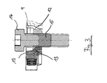
- the sheet metal strip has an oblique section that extends into an area below the screw head. This sloping section drops to the free end of the screw shaft. While dressing the clamping screw presses the clamping screw head from above onto the sloping section. As the screws are tightened further, the sloping section gives way from the side, which leads to the spring plate being bent up and from the outside presses against the profiling.
- a common two-armed anti-rotation element is provided his.
- the anti-rotation element preferably has the shape of a U. and is located in the area between the two adjustment screws.
- the tension screw is in the area between the legs of the U-shaped Anti-rotation element arranged. When tightening the clamping screw the legs are pushed apart by the tension screw head. The Legs of the U-shaped anti-rotation element are thus bent and pressed against the assigned adjustment screw.
- the profiling can be knurling, for example.
- the Adjusting screw an Allen screw, which is a very compact design and enables easy assembly.
- an adjustment hole can be provided, via which a hex key for loosening or tightening the Allen screw and a twisting tool for the Adjustment screw can be inserted without removing the cylinder head cover must be removed.
- Figure 1 shows two valve units 1, 2 of an electromagnetic valve drive device.
- Each of the two valve units 1, 2 has an adjusting screw 3, 4 an internal hexagon 5, 6, for attaching an adjusting tool is provided.
- an adjusting screw 3 an internal hexagon 5, 6, for attaching an adjusting tool is provided.
- an internal hexagon 5 6 for attaching an adjusting tool is provided.
- a hexagon socket another shape, e.g. a triangular shape.
- the adjusting screws 3, 4 are each screwed into an actuator housing 7. in the Inside the actuator housing 7 are provided for controlling the valves Setting anchor housed.
- Each of the two anchors can be made in a known manner be moved forward or backward by assigned electromagnets what a Allows opening and closing of the valves. This is detailed in the above described DE 694 09 485 T2, to which reference is made in full is taken.
- the electromagnets When the electromagnets are de-energized, the positioning anchors become by arranged one behind the other in the direction of displacement, in opposite directions Directional compression springs are kept in their respective neutral positions.
- On End of a compression spring of each pair of compression springs is assigned by the Adjusting screw 3, 4 supported. By turning the adjustment screw, the Bias of the associated pair of compression springs and the location of the The neutral position of the armature can be adjusted. This happens in the workshop.
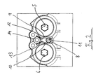
- the anti-rotation element 8 has here a symmetrical shape. More specifically, this is a U-shaped one Spring plate.
- the spring plate level or more precisely a "transverse direction" of the Spring plate is essentially parallel to the shaft directions of the two adjusting screws 3, 4.
- the U-shaped spring plate is in the connection area of it both legs 9, 10 by means of a fastening screw 11 on the actuator housing 7 attached.
- the free ends of the legs 9, 10 are bent outwards.
- the free ends each have an inward bent in their lower region sloping section 12, 13, which can be seen better from Figures 2, 3.
- a clamping screw is provided in the area of the free ends of the legs 9, 10, which has a clamping screw head 14 and a shaft 15.
- the Fastening screw 11 and the clamping screw 14 also each have here a hexagon socket.
- the adjusting screws 3, 4 there is a profiling or knurling 16, 17 provided.
- the outer sides of the legs 9, 10 be profiled or knurled. The legs 9, 10 thus grip and / or positively on the adjustment screws and prevent one automatic loosening and thus an automatic adjustment of the Spring preload and the neutral position of the actuator anchor plate.
Landscapes
- Engineering & Computer Science (AREA)
- Mechanical Engineering (AREA)
- General Engineering & Computer Science (AREA)
- Valve Device For Special Equipments (AREA)
Abstract
Description
- Figur 1
- Eine perspektivische Darstellung einer elektromagnetischen Ventiltriebvorrichtung mit zwei Ventileinheiten;
- Figur 2
- eine Draufsicht auf die beiden Ventileinheiten; und
- Figur 3
- einen Querschnitt im Bereich der Spannschraube des Verdrehsicherungselementes.
Claims (11)
- Elektromagnetische Ventiltriebvorrichtung für einen Verbrennungsmotor mit einem axial verschieblichen Stellglied zum Öffnen bzw. Schließen eines Ventils,
zwei in Verschieberichtung hintereinander angeordneten Federn, welche das Stellglied in einer Neutralstellung halten,
einer Verstellschraube (3, 4), mittels der die Vorspannung der Federn und die Lage der Neutralstellung des Stellglieds veränderbar ist, und
einem Verdrehsicherungselement (8), das von außen an der Verstellschraube (3, 4) angreift und eine selbsttätige Verdrehung der Verstellschraube (3, 4) verhindert,
dadurch gekennzeichnet, dass die Verstellschraube (8) an ihrer Außenseite eine Profilierung (16, 17) aufweist und dass das Verdrehsicherungselement ein Federblech ist, das von außen gegen die Profilierung drückt. - Elektromagnetische Ventiltriebvorrichtung nach Anspruch 1, wobei das Federblech (8) eine entsprechende Gegenprofilierung aufweist, die formschlüssig in die Profilierung eingreift.
- Elektromagnetische Ventiltriebvorrichtung nach Anspruch 1 oder 2, wobei das Federblech einen Federblecharm (9, 10) aufweist, dessen eines Ende an einem Halteelement (7) befestigt ist und dessen anderes Ende durch Festschrauben einer Spannschraube (14, 15) durch einen Kopf (14) der Spannschraube derart aufbiegbar ist, dass das Federblech (8) von außen gegen die Profilierung (16, 17) drückt.
- Elektromagnetische Ventiltriebvorrichtung nach einem der Ansprüche 1 bis 3, wobei das Federblech die Form eines Blechstreifens hat.
- Elektromagnetische Ventiltriebvorrichtung nach Anspruch 4, wobei eine Querrichtung des Blechstreifens im wesentlichen parallel zum Schaft (15) der Spannschraube (14, 15) ist.
- Elektromagnetische Ventiltriebvorrichtung nach einem Ansprüche 4 oder 5, wobei der Blechstreifen einen schrägen Abschnitt (12, 13) aufweist, der sich in einen Bereich unterhalb des Schraubenkopfes (14) erstreckt, wobei der schräge Abschnitt (12, 13) zum freien Ende des Schraubenschaftes (15) hin abfällt, so dass der Schraubenkopf (14) bei angezogener Spannschraube (13, 14) an dem schrägen Abschnitt (12, 13) anliegt und das Federblech (8) derart aufbiegt, dass es von außen gegen die Profilierung (16, 17) drückt.
- Elektromagnetische Ventiltriebvorrichtung nach einem der Ansprüche 1 bis 6, wobei zwei nebeneinander angeordnete Ventileinheiten (1, 2) vorgesehen sind, wobei jeder Ventileinheit (1, 2) jeweils eine solche Verstellschraube (3, 4) zugeordnet ist und dass im Bereich zwischen den beiden Ventileinheiten (1, 2) ein zweiarmiges Verdrehsicherungselement (8) angeordnet ist, das von außen gegen die Profilierungen (16, 17) der Verstellschrauben (3, 4) der Ventileinheiten (1, 2) drückt.
- Elektromagnetische Ventiltriebvorrichtung nach einem der Ansprüche 1 bis 7, wobei das Verdrehsicherungselement die Form eines U hat und die Spannschraube (14, 15) im Bereich der freien Enden der Schenkel (9, 10) des U-förmigen Verdrehsicherungselementes (8) angeordnet ist.
- Elektromagnetische Ventiltriebvorrichtung nach Anspruch 8, wobei im Bereich zwischen den beiden Schenkeln (9, 10) des U-förmigen Verdrehsicherungselements (8) das Verdrehsicherungselement (8) mittels einer Befestigungsschraube (11) an dem Halteelement (7) befestigt ist.
- Elektromagnetische Ventiltriebvorrichtung nach einem der Ansprüche 1 bis 9, wobei die Profilierung eine Rändelung ist.
- Elektromagnetische Ventiltriebvorrichtung nach einem der Ansprüche 1 bis 10, wobei die Verstellschraube (3, 4) und die Spannschraube (14, 15) jeweils Innensechskantschrauben sind.
Applications Claiming Priority (2)
| Application Number | Priority Date | Filing Date | Title |
|---|---|---|---|
| DE10248328A DE10248328A1 (de) | 2002-10-17 | 2002-10-17 | Elektromagnetische Ventiltriebvorrichtung mit verdrehgesicherter Neutrallagenverstellschraube |
| DE10248328 | 2002-10-17 |
Publications (3)
| Publication Number | Publication Date |
|---|---|
| EP1411212A2 true EP1411212A2 (de) | 2004-04-21 |
| EP1411212A3 EP1411212A3 (de) | 2004-04-28 |
| EP1411212B1 EP1411212B1 (de) | 2007-03-14 |
Family
ID=32038728
Family Applications (1)
| Application Number | Title | Priority Date | Filing Date |
|---|---|---|---|
| EP03021029A Expired - Lifetime EP1411212B1 (de) | 2002-10-17 | 2003-09-17 | Elektromagnetische Ventiltriebvorrichtung mit verdrehgesicherter Neutrallagenverstellschraube |
Country Status (2)
| Country | Link |
|---|---|
| EP (1) | EP1411212B1 (de) |
| DE (2) | DE10248328A1 (de) |
Cited By (1)
| Publication number | Priority date | Publication date | Assignee | Title |
|---|---|---|---|---|
| FR2870564A1 (fr) * | 2004-05-19 | 2005-11-25 | Peugeot Citroen Automobiles Sa | Dispositif d'actionnement de soupapes |
Citations (1)
| Publication number | Priority date | Publication date | Assignee | Title |
|---|---|---|---|---|
| DE69409485T2 (de) | 1994-01-07 | 1998-09-17 | Citroen Sa | Verfahren zur Steuerung eines bistabilen elektromagnetischen Stellgliedes und Vorrichtung zur Durchführung dieses Verfahrens |
Family Cites Families (7)
| Publication number | Priority date | Publication date | Assignee | Title |
|---|---|---|---|---|
| US1480318A (en) * | 1922-05-13 | 1924-01-08 | Valade Joseph Emile | Nut lock |
| DE3500530A1 (de) * | 1985-01-09 | 1986-07-10 | Binder Magnete GmbH, 7730 Villingen-Schwenningen | Vorrichtung zur elektromagnetischen steuerung von hubventilen |
| US6094118A (en) * | 1997-12-09 | 2000-07-25 | Siemens Automotive Corporation | Electromagnetic actuator with stamped steel housing |
| DE19826832A1 (de) * | 1998-06-16 | 1999-12-23 | Fev Motorentech Gmbh | Elektromagnetischer Aktuator für ein Gaswechselventil mit integriertem Ventilspielausgleich |
| FR2792679B1 (fr) * | 1999-04-23 | 2001-07-27 | Sagem | Dispositif reglable de commande de soupapes et procede de reglage d'un tel dispositif |
| DE10043803A1 (de) * | 2000-09-06 | 2002-03-14 | Daimler Chrysler Ag | Elektromagnetischer Aktuator |
| DE20109597U1 (de) * | 2001-06-08 | 2001-09-27 | TRW Deutschland GmbH, 30890 Barsinghausen | Vorrichtung zur Betätigung eines Gaswechselventils einer Brennkraftmaschine |
-
2002
- 2002-10-17 DE DE10248328A patent/DE10248328A1/de not_active Withdrawn
-
2003
- 2003-09-17 DE DE50306791T patent/DE50306791D1/de not_active Expired - Lifetime
- 2003-09-17 EP EP03021029A patent/EP1411212B1/de not_active Expired - Lifetime
Patent Citations (1)
| Publication number | Priority date | Publication date | Assignee | Title |
|---|---|---|---|---|
| DE69409485T2 (de) | 1994-01-07 | 1998-09-17 | Citroen Sa | Verfahren zur Steuerung eines bistabilen elektromagnetischen Stellgliedes und Vorrichtung zur Durchführung dieses Verfahrens |
Cited By (3)
| Publication number | Priority date | Publication date | Assignee | Title |
|---|---|---|---|---|
| FR2870564A1 (fr) * | 2004-05-19 | 2005-11-25 | Peugeot Citroen Automobiles Sa | Dispositif d'actionnement de soupapes |
| WO2005113946A1 (fr) * | 2004-05-19 | 2005-12-01 | Peugeot Citroen Automobiles | Dispositif d'actionnement de soupapes |
| US7654235B2 (en) | 2004-05-19 | 2010-02-02 | Peugeot Citroen Automobiles Sa | Valve actuating device |
Also Published As
| Publication number | Publication date |
|---|---|
| EP1411212B1 (de) | 2007-03-14 |
| DE10248328A1 (de) | 2004-04-29 |
| EP1411212A3 (de) | 2004-04-28 |
| DE50306791D1 (de) | 2007-04-26 |
Similar Documents
| Publication | Publication Date | Title |
|---|---|---|
| DE4219956C2 (de) | Schneideinrichtung für eine Motorkettensäge | |
| DE112009002211B4 (de) | Motorbremseinrichtung für eine Brennkraftmaschine | |
| DE60109883T2 (de) | Ventilaktuator mit einem Spielausgleichselement | |
| DE60032350T2 (de) | Verstellbare ventilsteurungseinrichtung und verfahren | |
| DE69703581T2 (de) | Brennkraftmaschine | |
| WO2014121984A1 (de) | Abgasturbolader mit einer regeleinheit | |
| EP2669534A2 (de) | Montageanordnung | |
| DE60217064T2 (de) | Kraftstoff-einspritzdüse | |
| DE3509479C2 (de) | Ventil zum Anbau an eine Betätigungseinrichtung | |
| EP1411212B1 (de) | Elektromagnetische Ventiltriebvorrichtung mit verdrehgesicherter Neutrallagenverstellschraube | |
| DE1931803A1 (de) | Stoesselanordnung fuer Ventiltriebe | |
| DE4410288C1 (de) | Ventilbetätigungsvorrichtung für eine Brennkraftmaschine | |
| DE102009038662B4 (de) | Ventiltrieb einer Brennkraftmaschine | |
| EP1473110B1 (de) | Spannelement zum Spannen von Werkstücken auf Maschinentischen, Vorrichtungen oder Paletten | |
| DE10031610A1 (de) | Kettenspanner | |
| DE10141176A1 (de) | Lösbare Verbindung zum Kuppeln eines Gaswechselventils einer Brennkraftmaschine mit einem Aktor | |
| EP0068337B1 (de) | Ventilbetätigungshebel für Brennkraftmaschinen | |
| EP2156021A1 (de) | Kipphebel einer brennkraftmaschine | |
| DE19746877B4 (de) | Vorrichtung zum Einstellen des Ventilspiels am Zylinderkopf einer Brennkraftmaschine | |
| EP0262167A1 (de) | Kraftstoffeinspritzpumpe für brennkraftmaschinen. | |
| EP1146205B1 (de) | Elektromagnetischer Aktuator mit Federhaltekappe zur Betätigung eines Gaswechselventils an einer Kolbenbrennkraftmaschine | |
| DE29601085U1 (de) | Steckschlüssel für Eckventile | |
| EP1063391A2 (de) | Ventiltrieb für eine Verbrennungskraftmaschine | |
| DE20218204U1 (de) | Halterung für Magnetfeldsensoren | |
| DE29924858U1 (de) | Ventiltrieb |
Legal Events
| Date | Code | Title | Description |
|---|---|---|---|
| PUAI | Public reference made under article 153(3) epc to a published international application that has entered the european phase |
Free format text: ORIGINAL CODE: 0009012 |
|
| PUAL | Search report despatched |
Free format text: ORIGINAL CODE: 0009013 |
|
| AK | Designated contracting states |
Kind code of ref document: A2 Designated state(s): AT BE BG CH CY CZ DE DK EE ES FI FR GB GR HU IE IT LI LU MC NL PT RO SE SI SK TR |
|
| AX | Request for extension of the european patent |
Extension state: AL LT LV MK |
|
| AK | Designated contracting states |
Kind code of ref document: A3 Designated state(s): AT BE BG CH CY CZ DE DK EE ES FI FR GB GR HU IE IT LI LU MC NL PT RO SE SI SK TR |
|
| AX | Request for extension of the european patent |
Extension state: AL LT LV MK |
|
| 17P | Request for examination filed |
Effective date: 20040320 |
|
| AKX | Designation fees paid |
Designated state(s): DE FR GB IT |
|
| GRAP | Despatch of communication of intention to grant a patent |
Free format text: ORIGINAL CODE: EPIDOSNIGR1 |
|
| GRAS | Grant fee paid |
Free format text: ORIGINAL CODE: EPIDOSNIGR3 |
|
| GRAA | (expected) grant |
Free format text: ORIGINAL CODE: 0009210 |
|
| AK | Designated contracting states |
Kind code of ref document: B1 Designated state(s): DE FR GB IT |
|
| REG | Reference to a national code |
Ref country code: GB Ref legal event code: FG4D Free format text: NOT ENGLISH |
|
| GBT | Gb: translation of ep patent filed (gb section 77(6)(a)/1977) |
Effective date: 20070314 |
|
| REF | Corresponds to: |
Ref document number: 50306791 Country of ref document: DE Date of ref document: 20070426 Kind code of ref document: P |
|
| ET | Fr: translation filed | ||
| PLBE | No opposition filed within time limit |
Free format text: ORIGINAL CODE: 0009261 |
|
| STAA | Information on the status of an ep patent application or granted ep patent |
Free format text: STATUS: NO OPPOSITION FILED WITHIN TIME LIMIT |
|
| 26N | No opposition filed |
Effective date: 20071217 |
|
| PGFP | Annual fee paid to national office [announced via postgrant information from national office to epo] |
Ref country code: DE Payment date: 20140919 Year of fee payment: 12 |
|
| PGFP | Annual fee paid to national office [announced via postgrant information from national office to epo] |
Ref country code: GB Payment date: 20140926 Year of fee payment: 12 |
|
| PGFP | Annual fee paid to national office [announced via postgrant information from national office to epo] |
Ref country code: IT Payment date: 20140924 Year of fee payment: 12 |
|
| REG | Reference to a national code |
Ref country code: FR Ref legal event code: PLFP Year of fee payment: 13 |
|
| PGFP | Annual fee paid to national office [announced via postgrant information from national office to epo] |
Ref country code: FR Payment date: 20150928 Year of fee payment: 13 |
|
| REG | Reference to a national code |
Ref country code: DE Ref legal event code: R119 Ref document number: 50306791 Country of ref document: DE |
|
| PG25 | Lapsed in a contracting state [announced via postgrant information from national office to epo] |
Ref country code: IT Free format text: LAPSE BECAUSE OF NON-PAYMENT OF DUE FEES Effective date: 20150917 |
|
| GBPC | Gb: european patent ceased through non-payment of renewal fee |
Effective date: 20150917 |
|
| PG25 | Lapsed in a contracting state [announced via postgrant information from national office to epo] |
Ref country code: GB Free format text: LAPSE BECAUSE OF NON-PAYMENT OF DUE FEES Effective date: 20150917 Ref country code: DE Free format text: LAPSE BECAUSE OF NON-PAYMENT OF DUE FEES Effective date: 20160401 |
|
| REG | Reference to a national code |
Ref country code: FR Ref legal event code: ST Effective date: 20170531 |
|
| PG25 | Lapsed in a contracting state [announced via postgrant information from national office to epo] |
Ref country code: FR Free format text: LAPSE BECAUSE OF NON-PAYMENT OF DUE FEES Effective date: 20160930 |