EP1410944A1 - Method for installing a catenary wire and machine - Google Patents
Method for installing a catenary wire and machine Download PDFInfo
- Publication number
- EP1410944A1 EP1410944A1 EP03450209A EP03450209A EP1410944A1 EP 1410944 A1 EP1410944 A1 EP 1410944A1 EP 03450209 A EP03450209 A EP 03450209A EP 03450209 A EP03450209 A EP 03450209A EP 1410944 A1 EP1410944 A1 EP 1410944A1
- Authority
- EP
- European Patent Office
- Prior art keywords
- winch
- cable
- machine
- catenary
- wheels
- Prior art date
- Legal status (The legal status is an assumption and is not a legal conclusion. Google has not performed a legal analysis and makes no representation as to the accuracy of the status listed.)
- Granted
Links
Images


Classifications
-
- B—PERFORMING OPERATIONS; TRANSPORTING
- B60—VEHICLES IN GENERAL
- B60M—POWER SUPPLY LINES, AND DEVICES ALONG RAILS, FOR ELECTRICALLY- PROPELLED VEHICLES
- B60M1/00—Power supply lines for contact with collector on vehicle
- B60M1/12—Trolley lines; Accessories therefor
- B60M1/28—Manufacturing or repairing trolley lines
Definitions
- the invention relates to a method for laying one of a contact wire or a suspension cable of a catenary of a track formed catenary cable, the withdrawn with a Trommelabzugskraft of a storage drum and with a rope tension over winch wheels of a friction winch is guided to from this with a withdrawal force Pull-off resistance for generating a laying voltage on a mounting roller to be delivered, as well as a machine for laying a catenary cable.
- the object of the present invention is now to provide a method the generic type, with the catenary cables with higher and constant laying stress easily from the storage drum are removable.
- this object is achieved with a method of the aforementioned Art solved by the fact that the rope tension between the winch wheels the friction winch successively increased to trigger resistance becomes.
- the machine 1 has a machine frame 5, which has two rail bogies 6 is supported on the track 4.
- a motor 7 and a hydraulic unit 8 are for the power supply of a traction drive 9 of the machine. 1 and all other to be described drives provided.
- the to be laid catenary 2 (trolley wire) is on a storage drum 10 wound, which is rotatable about an axis 11 on a transversely adjustable Carriage 12 is mounted.
- a mounting roller 36 having telescopic column 14th mounted on a support frame 15 which by a drive 35 to a in Machine longitudinal axis 16 extending relative to the machine frame 5 is pivotable.
- the friction winch 13 consists of a - with respect to a Umwicklungsraum 24 - first, second, third and fourth winch 17, 18, 19, 20 together, each independently rotatable about a rotation axis 21 are stored.
- the first and behind arranged in the machine direction behind second winch 17,18 and the third and fourth winch 19,20 are each arranged in a common plane 22 and each form a pair of wheels 23.
- the two levels are parallel to each other.
- the first or second winch wheel is 17,18 with respect to the respective axis of rotation 21 each coaxial with the third or fourth windmill 19,20 arranged.
- the second, third and fourth winch 18,19,20 each own hydraulic motor 25 is assigned.
- these wise each a different volume of intake (for example, 1100, 1800 and 2800 cc / rev) for a wrapping direction 24 from the second to the fourth Winch wheel 18,19,20 increasing torque.
- the Hydraulic motors 25 but also via a control system 26 with different Operating pressure to be applied.
- each winch 17 - 20 a Rope groove 27 provided on - with respect to the Umwicklungsraum 24 - second and third winch 18,19 wider than the first and fourth winch 17,20 is formed.
- the machine 1 In labor, the machine 1 is continuously in one direction 28 procedure.
- the catenary cable 2 is on a boom 29 of a mast attached and is due to the right of way of the machine 1 with a constant Pull-off force 30 for a final installation corresponding laying voltage deducted from the friction winch 13. This will be on the fourth winch 20 generates a pull-off force 30 opposing trigger resistance 31.
- the catenary cable 2 from the storage drum 10 in a lower level with a Trommelabzugskraft 37 on the first and in more Follow the second winch wheel 17,18 and from this in an upper level to the third and finally in the lower level to the fourth Winding wheel 20 guided in the respective cable groove 27.
- the fourth winch wheel 20 (the front winch wheel 18 is not shown) mounted on a rocker 32, which is parallel to the axis of rotation around a 21 extending axis 33 pivotally connected to the support frame 15th connected is.
- An opposite end of the rocker 32 is through a Pressure measuring pin 34 connected to the support frame 15. This can be done in Advantageously, the laying voltage measured exactly and via a control system kept constant.
- the friction winch 13 is seated from a first, second and third, with respect to the Umwicklungsraum 24, arranged in a common plane windmill 17,18,19 together, each with its own hydraulic motor 25 is assigned.
- the catenary rope 2 is defined by the first winch wheel 17 with a drum withdrawal force 37 (e.g. 5 kilonewtons) from a storage drum, not shown deducted. Due to the increased torque of the second winch wheel 18, the rope tension is increased to 15 kilonewtons. Finally, through the third winch 19, the rope tension and thus the trigger resistance 31 increased to 25 kilonewtons.
Landscapes
- Engineering & Computer Science (AREA)
- Manufacturing & Machinery (AREA)
- Mechanical Engineering (AREA)
- Electric Cable Installation (AREA)
- Orthopedics, Nursing, And Contraception (AREA)
Abstract
Description
Die Erfindung betrifft ein Verfahren zum Verlegen eines aus einem Fahrdraht oder einem Tragseil einer Fahrleitung eines Gleises gebildeten Fahrleitungsseiles, das mit einer Trommelabzugskraft von einer Speichertrommel abgezogen und mit einer Seilspannung über Windenräder einer Friktionswinde geführt wird, um von dieser mit einem einer Abzugskraft entgegengerichteten Abzugswiderstand zur Erzeugung einer Verlegespannung auf eine Montagerolle abgegeben zu werden, sowie eine Maschine zum Verlegen eines Fahrleitungsseiles.The invention relates to a method for laying one of a contact wire or a suspension cable of a catenary of a track formed catenary cable, the withdrawn with a Trommelabzugskraft of a storage drum and with a rope tension over winch wheels of a friction winch is guided to from this with a withdrawal force Pull-off resistance for generating a laying voltage on a mounting roller to be delivered, as well as a machine for laying a catenary cable.
Gemäß US 5 114 119 und EP 0 861 752 ist bereits eine derartige Maschine bekannt, mit der ein Fahrdraht und ein Tragseil einer elektrischen Oberleitung eines Gleises gemeinsam und mit der endgültigen Verlegespannung verlegt werden können. Fahrdraht und Tragseil werden dabei kontinuierlich von jeweils einer eigenen Speichertrommel abgezogen und durchlaufen eine Friktionswinde als Zugspannungsvorrichtung, bevor sie anhand einer Montagerolle in der korrekten Höhen- und Seitenlage für die Endmontage positioniert werden. Die Friktionswinde besteht aus zwei in Maschinenlängsrichtung hintereinander angeordneten Windenrädern, die durch einen gemeinsamen Hydraulikmotor angetrieben werden.According to US 5 114 119 and EP 0 861 752, such a machine already exists known, with a contact wire and a supporting cable of an electrical overhead line a track laid together and with the final installation voltage can be. Contact wire and suspension cable are thereby continuously from each deducted their own storage drum and go through a friction winds as Zugspannungsvorrichtung before using a mounting roller be positioned in the correct height and lateral position for final assembly. The friction winch consists of two consecutively in the machine direction arranged winch wheels, by a common hydraulic motor are driven.
Die Aufgabe der vorliegenden Erfindung liegt nun in der Schaffung eines Verfahrens der gattungsgemäßen Art, mit dem auch Fahrleitungsseile mit höherer und konstanter Verlegespannung problemlos von der Speichertrommel abziehbar sind.The object of the present invention is now to provide a method the generic type, with the catenary cables with higher and constant laying stress easily from the storage drum are removable.
Erfindungsgemäß wird diese Aufgabe mit einem Verfahren der eingangs genannten Art dadurch gelöst, dass die Seilspannung zwischen den Windenrädern der Friktionswinde sukzessive bis zum Abzugswiderstand gesteigert wird. According to the invention, this object is achieved with a method of the aforementioned Art solved by the fact that the rope tension between the winch wheels the friction winch successively increased to trigger resistance becomes.
Damit besteht in vorteilhafter Weise die Möglichkeit, die auf die Seilrillen der Windenräder einwirkenden Spannkräfte zur Verbesserung des Kraftschlusses stufenweise von einem zum nächsten Windenrad zu erhöhen, bis schließlich am letzten Windenrad die gewünschte Verlegespannung zur Wirkung kommt. Außerdem besteht durch die Anordnung mehrerer voneinander unabhängiger Antriebe der Vorteil, daß die Abzugskräfte wahlweise in einer großen Bandbreite von ca. 5 bis 30 Kilonewton problemlos variierbar sind und vor allem auch konstant gehalten werden können.This is advantageously the possibility of the rope grooves of the Winch wheels acting clamping forces to improve the frictional connection gradually increase from one to the next winch wheel, until finally At the last winch the desired laying tension comes into effect. In addition, the arrangement of several independent of each other Drives the advantage that the withdrawal forces either in a wide range from about 5 to 30 kilonewtons are easily variable and above all can also be kept constant.
Weitere Vorteile und Ausbildungen der Erfindung ergeben sich aus den weiteren Ansprüchen und der Zeichnung.Further advantages and embodiments of the invention will become apparent from the others Claims and the drawing.
Im folgenden wird die Erfindung anhand von in der Zeichnung dargestellten Ausführungsbeispielen näher beschrieben.In the following the invention with reference to shown in the drawing Embodiments described in more detail.
Es zeigen:
In Fig. 1 und 2 ist eine Maschine 1 zum Verlegen eines Fahrdrahtes (bzw.
auch eines nicht näher dargestellten Tragseiles) einer Fahrleitung 3 eines
Gleises 4 dargestellt. Der Einfachheit halber wird im folgenden als Fahrdraht
und Tragseil umfassender Ausdruck Fahrleitungsseil 2 verwendet. Die Maschine
1 weist einen Maschinenrahmen 5 auf, der über zwei Schienenfahrwerke
6 auf dem Gleis 4 abgestützt ist. Ein Motor 7 und ein Hydraulikaggregat
8 sind für die Energieversorgung eines Fahrantriebes 9 der Maschine 1
und aller weiteren noch zu beschreibenden Antriebe vorgesehen.In Fig. 1 and 2, a machine 1 for laying a contact wire (or
Also, a support cable not shown) of a catenary 3 a
Das zu verlegende Fahrleitungsseil 2 (Fahrdraht) ist auf einer Speichertrommel
10 aufgewickelt, die um eine Achse 11 drehbar auf einem querverstellbaren
Schlitten 12 gelagert ist. Dieser ist ebenso wie eine Friktionswinde 13 und
eine höhenverstellbare, eine Montagerolle 36 aufweisende Teleskopsäule 14
auf einem Trägerrahmen 15 befestigt, der durch einen Antrieb 35 um eine in
Maschinenlängsrichtung verlaufende Achse 16 relativ zum Maschinenrahmen
5 verschwenkbar ist.The to be laid catenary 2 (trolley wire) is on a
Die Friktionswinde 13 setzt sich aus einem - bezüglich einer Umwicklungsrichtung
24 - ersten, zweiten, dritten und vierten Windenrad 17,18,19,20 zusammen,
die jeweils unabhängig voneinander um eine Drehachse 21 drehbar
gelagert sind. Das erste und das in Maschinenlängsrichtung dahinter angeordnete
zweite Windenrad 17,18 bzw. das dritte und vierte Windenrad 19,20
sind jeweils in einer gemeinsamen Ebene 22 angeordnet und bilden jeweils
ein Radpaar 23. Die beiden Ebenen verlaufen parallel zueinander.The
Wie insbesondere in Fig. 4 ersichtlich, ist das erste bzw. zweite Windenrad
17,18 bezüglich der jeweiligen Drehachse 21 jeweils koaxial zum dritten bzw.
vierten Windenrad 19,20 angeordnet. Dem zweiten, dritten und vierten Windenrad
18,19,20 ist je ein eigener Hydraulikmotor 25 zugeordnet. Diese weisen
jeweils ein unterschiedliches Schluckvolumen (beispielsweise 1100, 1800
und 2800 ccm/U) für ein in Umwicklungsrichtung 24 vom zweiten zum vierten
Windenrad 18,19,20 ansteigendes Drehmoment auf. Wahlweise können die
Hydraulikmotoren 25 jedoch auch über ein Steuersystem 26 mit unterschiedlichem
Betriebsdruck beaufschlagt werden.As can be seen in particular in FIG. 4, the first or second winch wheel is
17,18 with respect to the respective axis of
Zur Aufnahme des Fahrleitungsseiles 2 ist auf jedem Windenrad 17 - 20 eine
Seilrille 27 vorgesehen, die am - bezüglich der Umwicklungsrichtung 24 -
zweiten und dritten Windenrad 18,19 breiter als am ersten und vierten Windenrad
17,20 ausgebildet ist.To accommodate the
Im Arbeitseinsatz wird die Maschine 1 kontinuierlich in einer Arbeitsrichtung
28 verfahren. Das Fahrleitungsseil 2 ist an einem Ausleger 29 eines Mastens
befestigt und wird infolge der Vorfahrt der Maschine 1 mit einer konstanten
Abzugskraft 30 für eine der Endmontage entsprechende Verlegespannung
von der Friktionswinde 13 abgezogen. Durch diese wird am vierten Windenrad
20 ein der Abzugskraft 30 entgegengerichteter Abzugswiderstand 31 erzeugt.
Dazu wird das Fahrleitungsseil 2 von der Speichertrommel 10 in einer
unteren Ebene mit einer Trommelabzugskraft 37 auf das erste und in weiterer
Folge auf das zweite Windenrad 17,18 und von diesem in einer oberen Ebene
zum dritten und schließlich wiederum in der unteren Ebene zum vierten
Windenrad 20 in der jeweiligen Seilrille 27 geführt.In labor, the machine 1 is continuously in one
Da das Drehmoment durch die unterschiedlichen Drehmomente der Hydraulikmotoren
25 sukzessive ansteigt, ist ein optimaler Kraftschluss des Fahrleitungsseiles
2 am jeweiligen Windenrad 17-20 gewährleistet. Wahlweise
könnte für das erste Windenrad 17 ebenfalls ein Hydraulikmotor verwendet
werden. Dies ist jedoch insoferne nicht sehr zweckmäßig, als der Umschlingungswinkel
des Fahrleitungsseiles 2 sehr gering ist.Because the torque due to the different torques of the
Gemäß Fig. 3 ist das vierte Windenrad 20 (das vordere Windenrad 18 ist
nicht dargestellt) auf einer Wippe 32 befestigt, die um eine parallel zur Drehachse
21 verlaufende Achse 33 verschwenkbar mit dem Trägerrahmen 15
verbunden ist. Ein gegenüberliegendes Ende der Wippe 32 ist durch einen
Druckmessbolzen 34 mit dem Trägerrahmen 15 verbunden. Damit kann in
vorteilhafter Weise die Verlegespannung exakt gemessen und über ein Regelsystem
konstant gehalten werden.According to FIG. 3, the fourth winch wheel 20 (the
Es ist natürlich auch möglich, die Maschine 1 - wie in der eingangs erwähnten
US 5 114 119 - zum gleichzeitigen Verlegen einer kompletten Fahrleitung 3
(Fahrdraht und Tragseil) auszubilden. Dazu wird eine weitere Speichertrommel
10, eine zweite Friktionswinde 13 und eine zusätzliche Montagerolle 36
benötigt. Diese können wahlweise am selben oder an einem zweiten Trägerrahmen
15 angeordnet werden.It is of course also possible, the machine 1 - as in the aforementioned
US 5 114 119 - for the simultaneous laying of a complete overhead line. 3
(Contact wire and carrying rope) form. This is another
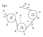
Gemäß einer in Fig. 5 dargestellten Variante setzt sich die Friktionswinde 13
aus einem bezüglich der Umwicklungsrichtung 24 ersten, zweiten und dritten,
in einer gemeinsamen Ebene angeordneten Windenrad 17,18,19 zusammen,
denen je ein eigener Hydraulikmotor 25 zugeordnet ist. Das Fahrleitungsseil
2 wird durch das erste Windenrad 17 mit einer Trommelabzugskraft 37 (beispielsweise
5 Kilonewton) von einer nicht näher dargestellten Speichertrommel
abgezogen. Durch das erhöhte Drehmoment des zweiten Windenrades
18 wird die Seilspannung auf 15 Kilonewton erhöht. Schließlich wird durch
das dritte Windenrad 19 die Seilspannung und damit der Abzugswiderstand
31 auf 25 Kilonewton erhöht.According to a variant illustrated in FIG. 5, the
Claims (10)
Applications Claiming Priority (2)
| Application Number | Priority Date | Filing Date | Title |
|---|---|---|---|
| AT0068902U AT6083U3 (en) | 2002-10-17 | 2002-10-17 | METHOD FOR LAYING A CABLES ROPE ROPE AND MACHINE |
| AT6892002 | 2002-10-17 |
Publications (2)
| Publication Number | Publication Date |
|---|---|
| EP1410944A1 true EP1410944A1 (en) | 2004-04-21 |
| EP1410944B1 EP1410944B1 (en) | 2006-06-21 |
Family
ID=3497206
Family Applications (1)
| Application Number | Title | Priority Date | Filing Date |
|---|---|---|---|
| EP03450209A Expired - Lifetime EP1410944B1 (en) | 2002-10-17 | 2003-09-17 | Method for installing a catenary wire and machine |
Country Status (11)
| Country | Link |
|---|---|
| US (1) | US7048256B2 (en) |
| EP (1) | EP1410944B1 (en) |
| JP (1) | JP4235526B2 (en) |
| CN (1) | CN1304219C (en) |
| AT (2) | AT6083U3 (en) |
| AU (1) | AU2003254751B2 (en) |
| DE (1) | DE50303922D1 (en) |
| DK (1) | DK1410944T3 (en) |
| ES (1) | ES2265096T3 (en) |
| PL (1) | PL206351B1 (en) |
| RU (1) | RU2248894C1 (en) |
Cited By (2)
| Publication number | Priority date | Publication date | Assignee | Title |
|---|---|---|---|---|
| CN103863957A (en) * | 2013-12-31 | 2014-06-18 | 三一汽车起重机械有限公司 | Auxiliary arm forming mode identification method and system and engineering machinery |
| CN110668326A (en) * | 2019-10-24 | 2020-01-10 | 广州供电局有限公司 | Cable lifting device and processing method |
Families Citing this family (12)
| Publication number | Priority date | Publication date | Assignee | Title |
|---|---|---|---|---|
| CN101337515B (en) * | 2008-01-29 | 2011-04-06 | 中铁四局集团有限公司 | Construction method for integral dropper of simple chain type suspension contact network of electrified railway |
| KR100966495B1 (en) * | 2008-05-29 | 2010-06-29 | 주식회사 동해 | A Cable Installing Device By Using Double Braid Rope |
| KR101044263B1 (en) | 2009-04-07 | 2011-06-28 | (주)디.에이치.케이 | A Cable Installing Device By Using Double Braid Rope |
| CN201457123U (en) * | 2009-07-16 | 2010-05-12 | 中铁电气化工具公司 | Digital-display type installation instrument for elastic sling of electrified contact net |
| AT14422U1 (en) * | 2014-01-13 | 2015-11-15 | Plasser & Theurer Export Von Bahnbaumaschinen Gmbh | Machine for laying a catenary cable |
| CN104709776A (en) * | 2015-03-19 | 2015-06-17 | 帕罗(上海)海洋工程有限公司 | Middle transmission device used for cable and steel wire rope |
| IT201600082789A1 (en) * | 2016-08-05 | 2018-02-05 | Tesmec Spa | AUTOMATIC RAILWAY POSITIONING SYSTEM |
| CN106251978A (en) * | 2016-08-31 | 2016-12-21 | 方电气股份有限公司 | Carry double plate actinobacillus device and the using method of damping |
| CN107380012B (en) * | 2017-07-31 | 2019-11-12 | 中铁电气化局集团有限公司 | Existing electrified railway contact net holds, leads the synchronous replacement construction technology of two-wire |
| CN112670901A (en) * | 2020-12-16 | 2021-04-16 | 国网山东省电力公司建设公司 | Cable erecting device for electric power construction and construction method thereof |
| CN113184682B (en) * | 2021-05-18 | 2022-07-19 | 国家电网有限公司 | Cable laying hanger convenient to install and use |
| CN117134251B (en) * | 2023-09-07 | 2024-06-18 | 国网四川省电力公司德阳供电公司 | Unmanned aerial vehicle hoisting follow-up pulley for power transmission line maintenance |
Citations (3)
| Publication number | Priority date | Publication date | Assignee | Title |
|---|---|---|---|---|
| GB1379791A (en) * | 1971-03-11 | 1975-01-08 | Japan National Railway | Isntallation of overhead conductor wires of railways |
| EP0861752A1 (en) * | 1997-02-17 | 1998-09-02 | Franz Plasser Bahnbaumaschinen-Industriegesellschaft m.b.H. | Installation machine for a catenery line |
| EP1231097A1 (en) * | 2001-02-09 | 2002-08-14 | Tesmec SpA | Method to regulate the tension for stretching machines and relative apparatus |
Family Cites Families (5)
| Publication number | Priority date | Publication date | Assignee | Title |
|---|---|---|---|---|
| JPS5914370B2 (en) * | 1978-10-30 | 1984-04-04 | 富士重工業株式会社 | Overhead line car equipment |
| US4624450A (en) * | 1984-09-20 | 1986-11-25 | Paccar Inc. | Constant tension hoisting system |
| JPS6192110A (en) * | 1984-10-11 | 1986-05-10 | 日本電信電話株式会社 | Cable traction device |
| ES2041343T3 (en) | 1988-10-14 | 1993-11-16 | Franz Plasser Bahnbaumaschinen- Industriegesellschaft M.B.H. | MOBILE MACHINE ON TRACKS FOR THE LAYING OF THE SUPPLY WIRE AND / OR THE SUPPORTING CABLE OF AN AIRLINE OF POWER SUPPLY. |
| US5826860A (en) * | 1995-12-01 | 1998-10-27 | Franz Plasser Bahnbaumaschinen-Industriegesellschaft M.B.H. | Machine for laying an overhead line of a track |
-
2002
- 2002-10-17 AT AT0068902U patent/AT6083U3/en not_active IP Right Cessation
-
2003
- 2003-09-17 DK DK03450209T patent/DK1410944T3/en active
- 2003-09-17 EP EP03450209A patent/EP1410944B1/en not_active Expired - Lifetime
- 2003-09-17 DE DE50303922T patent/DE50303922D1/en not_active Expired - Lifetime
- 2003-09-17 AT AT03450209T patent/ATE330811T1/en active
- 2003-09-17 ES ES03450209T patent/ES2265096T3/en not_active Expired - Lifetime
- 2003-10-10 US US10/683,721 patent/US7048256B2/en not_active Expired - Fee Related
- 2003-10-14 PL PL362831A patent/PL206351B1/en unknown
- 2003-10-14 JP JP2003353489A patent/JP4235526B2/en not_active Expired - Fee Related
- 2003-10-16 AU AU2003254751A patent/AU2003254751B2/en not_active Ceased
- 2003-10-17 RU RU2003130624/11A patent/RU2248894C1/en not_active IP Right Cessation
- 2003-10-17 CN CNB2003101024024A patent/CN1304219C/en not_active Expired - Fee Related
Patent Citations (3)
| Publication number | Priority date | Publication date | Assignee | Title |
|---|---|---|---|---|
| GB1379791A (en) * | 1971-03-11 | 1975-01-08 | Japan National Railway | Isntallation of overhead conductor wires of railways |
| EP0861752A1 (en) * | 1997-02-17 | 1998-09-02 | Franz Plasser Bahnbaumaschinen-Industriegesellschaft m.b.H. | Installation machine for a catenery line |
| EP1231097A1 (en) * | 2001-02-09 | 2002-08-14 | Tesmec SpA | Method to regulate the tension for stretching machines and relative apparatus |
Cited By (3)
| Publication number | Priority date | Publication date | Assignee | Title |
|---|---|---|---|---|
| CN103863957A (en) * | 2013-12-31 | 2014-06-18 | 三一汽车起重机械有限公司 | Auxiliary arm forming mode identification method and system and engineering machinery |
| CN103863957B (en) * | 2013-12-31 | 2016-05-11 | 三一汽车起重机械有限公司 | The recognition methods of auxiliary building form and system and engineering machinery |
| CN110668326A (en) * | 2019-10-24 | 2020-01-10 | 广州供电局有限公司 | Cable lifting device and processing method |
Also Published As
| Publication number | Publication date |
|---|---|
| PL206351B1 (en) | 2010-07-30 |
| RU2248894C1 (en) | 2005-03-27 |
| DE50303922D1 (en) | 2006-08-03 |
| CN1304219C (en) | 2007-03-14 |
| US20040075010A1 (en) | 2004-04-22 |
| AT6083U2 (en) | 2003-04-25 |
| ES2265096T3 (en) | 2007-02-01 |
| PL362831A1 (en) | 2004-04-19 |
| US7048256B2 (en) | 2006-05-23 |
| AU2003254751A1 (en) | 2004-05-06 |
| AT6083U3 (en) | 2004-07-26 |
| CN1496890A (en) | 2004-05-19 |
| DK1410944T3 (en) | 2006-09-11 |
| AU2003254751B2 (en) | 2008-06-05 |
| ATE330811T1 (en) | 2006-07-15 |
| EP1410944B1 (en) | 2006-06-21 |
| JP2004136872A (en) | 2004-05-13 |
| JP4235526B2 (en) | 2009-03-11 |
Similar Documents
| Publication | Publication Date | Title |
|---|---|---|
| EP0459538B1 (en) | Railroad machine to lay the power and/or supporting wire of track overhead line | |
| EP1410944A1 (en) | Method for installing a catenary wire and machine | |
| DE102011001712B4 (en) | Current collector system and installation | |
| EP0088868A1 (en) | Underground railless vehicle | |
| EP2363314A1 (en) | Device for coupling elastic and rigid contact wire systems | |
| AT6149U1 (en) | MACHINE FOR LAYING A CABINET LINE | |
| EP0897826B1 (en) | Catenary wire stringing device | |
| DE102019214959A1 (en) | Non-track-bound vehicle with a pantograph | |
| EP0861752B1 (en) | Installation machine for a catenery line | |
| DE2211247B2 (en) | PROCEDURE FOR INSTALLING AN OVERHEAD LINE FOR RAILWAYS AND DEVICE FOR CARRYING OUT THE PROCEDURE | |
| EP2401169B1 (en) | Current collector and energy transmission system | |
| EP1706305A2 (en) | Vehicle comprising a working platform | |
| DE10007093C2 (en) | Overhead line service facility | |
| EP0706910B1 (en) | Machine for the continuous installing of a power line of an electrical catenary | |
| DE4334063C1 (en) | Device for laying overhead railway power lines | |
| AT509734B1 (en) | PROCESS FOR ESTABLISHING AN ELECTRIC SUPPLY | |
| DE102012218223B4 (en) | Extraction device for extrusion presses for removing profiles from an extrusion press | |
| EP1123830B1 (en) | Method and machine for installation of a catenary wire | |
| EP0713799B1 (en) | Machine for maintenance of a railway overhead line | |
| EP0740619B1 (en) | Device for laying wires, cables or the like | |
| AT513716B1 (en) | Machine for laying catenary cables | |
| DE10138294C5 (en) | Method and device for replacing a contact wire on a catenary | |
| DE69104250T2 (en) | Device for driving rods into the ground, in particular for soil mechanics studies. | |
| WO2019101462A1 (en) | Overhead line system | |
| WO2015104046A1 (en) | Machine for laying an overhead contact line |
Legal Events
| Date | Code | Title | Description |
|---|---|---|---|
| PUAI | Public reference made under article 153(3) epc to a published international application that has entered the european phase |
Free format text: ORIGINAL CODE: 0009012 |
|
| AK | Designated contracting states |
Kind code of ref document: A1 Designated state(s): AT BE BG CH CY CZ DE DK EE ES FI FR GB GR HU IE IT LI LU MC NL PT RO SE SI SK TR |
|
| AX | Request for extension of the european patent |
Extension state: AL LT LV MK |
|
| 17P | Request for examination filed |
Effective date: 20041021 |
|
| AKX | Designation fees paid |
Designated state(s): AT BE BG CH CY CZ DE DK EE ES FI FR GB GR HU IE IT LI LU MC NL PT RO SE SI SK TR |
|
| 17Q | First examination report despatched |
Effective date: 20050503 |
|
| GRAP | Despatch of communication of intention to grant a patent |
Free format text: ORIGINAL CODE: EPIDOSNIGR1 |
|
| GRAS | Grant fee paid |
Free format text: ORIGINAL CODE: EPIDOSNIGR3 |
|
| GRAA | (expected) grant |
Free format text: ORIGINAL CODE: 0009210 |
|
| AK | Designated contracting states |
Kind code of ref document: B1 Designated state(s): AT BE BG CH CY CZ DE DK EE ES FI FR GB GR HU IE IT LI LU MC NL PT RO SE SI SK TR |
|
| PG25 | Lapsed in a contracting state [announced via postgrant information from national office to epo] |
Ref country code: IE Free format text: LAPSE BECAUSE OF FAILURE TO SUBMIT A TRANSLATION OF THE DESCRIPTION OR TO PAY THE FEE WITHIN THE PRESCRIBED TIME-LIMIT Effective date: 20060621 Ref country code: FI Free format text: LAPSE BECAUSE OF FAILURE TO SUBMIT A TRANSLATION OF THE DESCRIPTION OR TO PAY THE FEE WITHIN THE PRESCRIBED TIME-LIMIT Effective date: 20060621 Ref country code: SK Free format text: LAPSE BECAUSE OF FAILURE TO SUBMIT A TRANSLATION OF THE DESCRIPTION OR TO PAY THE FEE WITHIN THE PRESCRIBED TIME-LIMIT Effective date: 20060621 Ref country code: RO Free format text: LAPSE BECAUSE OF FAILURE TO SUBMIT A TRANSLATION OF THE DESCRIPTION OR TO PAY THE FEE WITHIN THE PRESCRIBED TIME-LIMIT Effective date: 20060621 Ref country code: SI Free format text: LAPSE BECAUSE OF FAILURE TO SUBMIT A TRANSLATION OF THE DESCRIPTION OR TO PAY THE FEE WITHIN THE PRESCRIBED TIME-LIMIT Effective date: 20060621 |
|
| REG | Reference to a national code |
Ref country code: GB Ref legal event code: FG4D Free format text: NOT ENGLISH |
|
| REG | Reference to a national code |
Ref country code: CH Ref legal event code: EP |
|
| REG | Reference to a national code |
Ref country code: IE Ref legal event code: FG4D Free format text: LANGUAGE OF EP DOCUMENT: GERMAN |
|
| REF | Corresponds to: |
Ref document number: 50303922 Country of ref document: DE Date of ref document: 20060803 Kind code of ref document: P |
|
| GBT | Gb: translation of ep patent filed (gb section 77(6)(a)/1977) | ||
| REG | Reference to a national code |
Ref country code: DK Ref legal event code: T3 |
|
| PG25 | Lapsed in a contracting state [announced via postgrant information from national office to epo] |
Ref country code: MC Free format text: LAPSE BECAUSE OF NON-PAYMENT OF DUE FEES Effective date: 20060930 |
|
| REG | Reference to a national code |
Ref country code: SE Ref legal event code: TRGR |
|
| REG | Reference to a national code |
Ref country code: HU Ref legal event code: AG4A Ref document number: E000660 Country of ref document: HU |
|
| PG25 | Lapsed in a contracting state [announced via postgrant information from national office to epo] |
Ref country code: PT Free format text: LAPSE BECAUSE OF FAILURE TO SUBMIT A TRANSLATION OF THE DESCRIPTION OR TO PAY THE FEE WITHIN THE PRESCRIBED TIME-LIMIT Effective date: 20061121 |
|
| ET | Fr: translation filed | ||
| REG | Reference to a national code |
Ref country code: ES Ref legal event code: FG2A Ref document number: 2265096 Country of ref document: ES Kind code of ref document: T3 |
|
| REG | Reference to a national code |
Ref country code: IE Ref legal event code: FD4D |
|
| PLBE | No opposition filed within time limit |
Free format text: ORIGINAL CODE: 0009261 |
|
| STAA | Information on the status of an ep patent application or granted ep patent |
Free format text: STATUS: NO OPPOSITION FILED WITHIN TIME LIMIT |
|
| 26N | No opposition filed |
Effective date: 20070322 |
|
| PG25 | Lapsed in a contracting state [announced via postgrant information from national office to epo] |
Ref country code: GR Free format text: LAPSE BECAUSE OF FAILURE TO SUBMIT A TRANSLATION OF THE DESCRIPTION OR TO PAY THE FEE WITHIN THE PRESCRIBED TIME-LIMIT Effective date: 20060922 |
|
| PG25 | Lapsed in a contracting state [announced via postgrant information from national office to epo] |
Ref country code: BG Free format text: LAPSE BECAUSE OF FAILURE TO SUBMIT A TRANSLATION OF THE DESCRIPTION OR TO PAY THE FEE WITHIN THE PRESCRIBED TIME-LIMIT Effective date: 20060921 Ref country code: EE Free format text: LAPSE BECAUSE OF FAILURE TO SUBMIT A TRANSLATION OF THE DESCRIPTION OR TO PAY THE FEE WITHIN THE PRESCRIBED TIME-LIMIT Effective date: 20060621 |
|
| PG25 | Lapsed in a contracting state [announced via postgrant information from national office to epo] |
Ref country code: TR Free format text: LAPSE BECAUSE OF FAILURE TO SUBMIT A TRANSLATION OF THE DESCRIPTION OR TO PAY THE FEE WITHIN THE PRESCRIBED TIME-LIMIT Effective date: 20060621 Ref country code: LU Free format text: LAPSE BECAUSE OF NON-PAYMENT OF DUE FEES Effective date: 20060917 |
|
| PG25 | Lapsed in a contracting state [announced via postgrant information from national office to epo] |
Ref country code: CY Free format text: LAPSE BECAUSE OF FAILURE TO SUBMIT A TRANSLATION OF THE DESCRIPTION OR TO PAY THE FEE WITHIN THE PRESCRIBED TIME-LIMIT Effective date: 20060621 |
|
| PGFP | Annual fee paid to national office [announced via postgrant information from national office to epo] |
Ref country code: DK Payment date: 20130917 Year of fee payment: 11 Ref country code: HU Payment date: 20130911 Year of fee payment: 11 Ref country code: CZ Payment date: 20130911 Year of fee payment: 11 |
|
| REG | Reference to a national code |
Ref country code: DE Ref legal event code: R082 Ref document number: 50303922 Country of ref document: DE Representative=s name: RAU, SCHNECK & HUEBNER PATENTANWAELTE RECHTSAN, DE |
|
| REG | Reference to a national code |
Ref country code: DE Ref legal event code: R081 Ref document number: 50303922 Country of ref document: DE Owner name: PLASSER & THEURER, EXPORT VON BAHNBAUMASCHINEN, AT Free format text: FORMER OWNER: FRANZ PLASSER BAHNBAUMASCHINEN-INDUSTRIEGESELLSCHAFT M.B.H., WIEN, AT Effective date: 20141001 Ref country code: DE Ref legal event code: R082 Ref document number: 50303922 Country of ref document: DE Representative=s name: RAU, SCHNECK & HUEBNER PATENTANWAELTE RECHTSAN, DE Effective date: 20141001 |
|
| REG | Reference to a national code |
Ref country code: DK Ref legal event code: EBP Effective date: 20140930 |
|
| PG25 | Lapsed in a contracting state [announced via postgrant information from national office to epo] |
Ref country code: CZ Free format text: LAPSE BECAUSE OF NON-PAYMENT OF DUE FEES Effective date: 20140917 |
|
| PG25 | Lapsed in a contracting state [announced via postgrant information from national office to epo] |
Ref country code: HU Free format text: LAPSE BECAUSE OF NON-PAYMENT OF DUE FEES Effective date: 20140918 |
|
| REG | Reference to a national code |
Ref country code: FR Ref legal event code: PLFP Year of fee payment: 13 |
|
| PG25 | Lapsed in a contracting state [announced via postgrant information from national office to epo] |
Ref country code: DK Free format text: LAPSE BECAUSE OF NON-PAYMENT OF DUE FEES Effective date: 20140930 |
|
| REG | Reference to a national code |
Ref country code: FR Ref legal event code: PLFP Year of fee payment: 14 |
|
| REG | Reference to a national code |
Ref country code: FR Ref legal event code: PLFP Year of fee payment: 15 |
|
| PGFP | Annual fee paid to national office [announced via postgrant information from national office to epo] |
Ref country code: IT Payment date: 20170926 Year of fee payment: 15 |
|
| PGFP | Annual fee paid to national office [announced via postgrant information from national office to epo] |
Ref country code: NL Payment date: 20170915 Year of fee payment: 15 |
|
| REG | Reference to a national code |
Ref country code: FR Ref legal event code: PLFP Year of fee payment: 16 |
|
| PGFP | Annual fee paid to national office [announced via postgrant information from national office to epo] |
Ref country code: TR Payment date: 20180716 Year of fee payment: 6 Ref country code: GB Payment date: 20180823 Year of fee payment: 16 |
|
| PGFP | Annual fee paid to national office [announced via postgrant information from national office to epo] |
Ref country code: ES Payment date: 20181107 Year of fee payment: 16 |
|
| REG | Reference to a national code |
Ref country code: NL Ref legal event code: MM Effective date: 20181001 |
|
| PG25 | Lapsed in a contracting state [announced via postgrant information from national office to epo] |
Ref country code: NL Free format text: LAPSE BECAUSE OF NON-PAYMENT OF DUE FEES Effective date: 20181001 |
|
| PG25 | Lapsed in a contracting state [announced via postgrant information from national office to epo] |
Ref country code: IT Free format text: LAPSE BECAUSE OF NON-PAYMENT OF DUE FEES Effective date: 20180917 |
|
| PGFP | Annual fee paid to national office [announced via postgrant information from national office to epo] |
Ref country code: FR Payment date: 20190916 Year of fee payment: 17 |
|
| PG25 | Lapsed in a contracting state [announced via postgrant information from national office to epo] |
Ref country code: SE Free format text: LAPSE BECAUSE OF NON-PAYMENT OF DUE FEES Effective date: 20190918 |
|
| REG | Reference to a national code |
Ref country code: SE Ref legal event code: EUG |
|
| REG | Reference to a national code |
Ref country code: BE Ref legal event code: MM Effective date: 20190930 |
|
| PG25 | Lapsed in a contracting state [announced via postgrant information from national office to epo] |
Ref country code: BE Free format text: LAPSE BECAUSE OF NON-PAYMENT OF DUE FEES Effective date: 20190930 |
|
| GBPC | Gb: european patent ceased through non-payment of renewal fee |
Effective date: 20190917 |
|
| PG25 | Lapsed in a contracting state [announced via postgrant information from national office to epo] |
Ref country code: GB Free format text: LAPSE BECAUSE OF NON-PAYMENT OF DUE FEES Effective date: 20190917 |
|
| PGFP | Annual fee paid to national office [announced via postgrant information from national office to epo] |
Ref country code: CH Payment date: 20200916 Year of fee payment: 18 |
|
| REG | Reference to a national code |
Ref country code: ES Ref legal event code: FD2A Effective date: 20210128 |
|
| PGFP | Annual fee paid to national office [announced via postgrant information from national office to epo] |
Ref country code: DE Payment date: 20201123 Year of fee payment: 18 |
|
| PG25 | Lapsed in a contracting state [announced via postgrant information from national office to epo] |
Ref country code: ES Free format text: LAPSE BECAUSE OF NON-PAYMENT OF DUE FEES Effective date: 20190918 |
|
| PG25 | Lapsed in a contracting state [announced via postgrant information from national office to epo] |
Ref country code: FR Free format text: LAPSE BECAUSE OF NON-PAYMENT OF DUE FEES Effective date: 20200930 |
|
| PGFP | Annual fee paid to national office [announced via postgrant information from national office to epo] |
Ref country code: AT Payment date: 20210810 Year of fee payment: 19 |
|
| REG | Reference to a national code |
Ref country code: DE Ref legal event code: R119 Ref document number: 50303922 Country of ref document: DE |
|
| REG | Reference to a national code |
Ref country code: CH Ref legal event code: PL |
|
| PG25 | Lapsed in a contracting state [announced via postgrant information from national office to epo] |
Ref country code: DE Free format text: LAPSE BECAUSE OF NON-PAYMENT OF DUE FEES Effective date: 20220401 |
|
| PG25 | Lapsed in a contracting state [announced via postgrant information from national office to epo] |
Ref country code: LI Free format text: LAPSE BECAUSE OF NON-PAYMENT OF DUE FEES Effective date: 20210930 Ref country code: CH Free format text: LAPSE BECAUSE OF NON-PAYMENT OF DUE FEES Effective date: 20210930 |
|
| REG | Reference to a national code |
Ref country code: AT Ref legal event code: MM01 Ref document number: 330811 Country of ref document: AT Kind code of ref document: T Effective date: 20220917 |
|
| PG25 | Lapsed in a contracting state [announced via postgrant information from national office to epo] |
Ref country code: AT Free format text: LAPSE BECAUSE OF NON-PAYMENT OF DUE FEES Effective date: 20220917 |