EP1410898A1 - Method of forming tire component member - Google Patents
Method of forming tire component member Download PDFInfo
- Publication number
- EP1410898A1 EP1410898A1 EP02738745A EP02738745A EP1410898A1 EP 1410898 A1 EP1410898 A1 EP 1410898A1 EP 02738745 A EP02738745 A EP 02738745A EP 02738745 A EP02738745 A EP 02738745A EP 1410898 A1 EP1410898 A1 EP 1410898A1
- Authority
- EP
- European Patent Office
- Prior art keywords
- drum
- forming
- band
- transfer drum
- shaped member
- Prior art date
- Legal status (The legal status is an assumption and is not a legal conclusion. Google has not performed a legal analysis and makes no representation as to the accuracy of the status listed.)
- Granted
Links
Images


Classifications
-
- B—PERFORMING OPERATIONS; TRANSPORTING
- B29—WORKING OF PLASTICS; WORKING OF SUBSTANCES IN A PLASTIC STATE IN GENERAL
- B29D—PRODUCING PARTICULAR ARTICLES FROM PLASTICS OR FROM SUBSTANCES IN A PLASTIC STATE
- B29D30/00—Producing pneumatic or solid tyres or parts thereof
- B29D30/06—Pneumatic tyres or parts thereof (e.g. produced by casting, moulding, compression moulding, injection moulding, centrifugal casting)
- B29D30/38—Textile inserts, e.g. cord or canvas layers, for tyres; Treatment of inserts prior to building the tyre
- B29D30/44—Stretching or treating the layers before application on the drum
-
- B—PERFORMING OPERATIONS; TRANSPORTING
- B29—WORKING OF PLASTICS; WORKING OF SUBSTANCES IN A PLASTIC STATE IN GENERAL
- B29D—PRODUCING PARTICULAR ARTICLES FROM PLASTICS OR FROM SUBSTANCES IN A PLASTIC STATE
- B29D30/00—Producing pneumatic or solid tyres or parts thereof
- B29D30/06—Pneumatic tyres or parts thereof (e.g. produced by casting, moulding, compression moulding, injection moulding, centrifugal casting)
- B29D30/08—Building tyres
- B29D30/20—Building tyres by the flat-tyre method, i.e. building on cylindrical drums
- B29D30/24—Drums
- B29D2030/241—Auxiliary drums used for temporary storage of the layers before application to the building drums
-
- Y—GENERAL TAGGING OF NEW TECHNOLOGICAL DEVELOPMENTS; GENERAL TAGGING OF CROSS-SECTIONAL TECHNOLOGIES SPANNING OVER SEVERAL SECTIONS OF THE IPC; TECHNICAL SUBJECTS COVERED BY FORMER USPC CROSS-REFERENCE ART COLLECTIONS [XRACs] AND DIGESTS
- Y10—TECHNICAL SUBJECTS COVERED BY FORMER USPC
- Y10S—TECHNICAL SUBJECTS COVERED BY FORMER USPC CROSS-REFERENCE ART COLLECTIONS [XRACs] AND DIGESTS
- Y10S156/00—Adhesive bonding and miscellaneous chemical manufacture
- Y10S156/906—Off-drum manufacture of tire fabric or ply
-
- Y—GENERAL TAGGING OF NEW TECHNOLOGICAL DEVELOPMENTS; GENERAL TAGGING OF CROSS-SECTIONAL TECHNOLOGIES SPANNING OVER SEVERAL SECTIONS OF THE IPC; TECHNICAL SUBJECTS COVERED BY FORMER USPC CROSS-REFERENCE ART COLLECTIONS [XRACs] AND DIGESTS
- Y10—TECHNICAL SUBJECTS COVERED BY FORMER USPC
- Y10T—TECHNICAL SUBJECTS COVERED BY FORMER US CLASSIFICATION
- Y10T156/00—Adhesive bonding and miscellaneous chemical manufacture
- Y10T156/10—Methods of surface bonding and/or assembly therefor
- Y10T156/1052—Methods of surface bonding and/or assembly therefor with cutting, punching, tearing or severing
- Y10T156/1062—Prior to assembly
- Y10T156/1075—Prior to assembly of plural laminae from single stock and assembling to each other or to additional lamina
Definitions
- the present invention relates to a tire structural member forming method of forming a tire structural member, such as plies or an inner liner, on a forming drum.
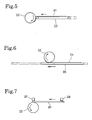
- One of three types of tire structural member forming systems shown in Figs. 5 to 7 is used for forming an annular tire structural member of an automotive tire by winding a band-shaped member of a predetermined length around a forming drum and bonding together the leading and the trailing end of the band-shaped member.
- the first tire structural member forming system shown in Fig. 5 carries a band-shaped member 01 by a conveyor belt 03 to feed the band-shaped member 01 to a forming drum 02 disposed close to the delivery end of the conveyor belt 03.
- the belt-shaped member 01 is wound around the forming drum 02 from its leading edge.
- the second tire structural member forming system shown in Fig. 6 places a band-shaped member 01 on a flat plate 05 and moves the flat plate 05 supporting the band-shaped member 01 horizontally to bring the band-shaped member 01 close to a rotating forming drum 02. Then, the band-shaped member 01 is wound from its leading edge around the rotating forming drum 02.
- the third tire structural member forming system shown in Fig. 7 carries a band-shaped member 01 of a predetermined length by robot hands 07 and 08.
- the robot hands 07 and 08 hold the band-shaped member 01 at the leading end and at the trailing end, respectively, by gripping or by suction and carry the band-shaped member 01 to a forming drum 02.
- the robot hand 07 releases the leading end of the band-shaped member 01 at a position corresponding to the circumference of the forming drum 02.
- the forming drum 02 is rotated and the other robot hand 08 is moved as the band-shaped member 01 is wound around the forming drum 02.
- the conveyor belt 03 meanders. Therefore, it is possible that the band-shaped member 01 cannot be correctly located (centered) relative to the forming drum 02.
- the band-shaped member 01 of a predetermined length is built by successively superposing and bonding together strips obtained by cutting a long band in the predetermined length on the conveyor belt 03 with their edges trued up, the strips cannot be accurately bonded together because the feed rate of the conveyor belt 03 varies.
- the band-shaped member 01 When the band-shaped member 01 is carried by the second tire structural member forming system using the flat plate 05 as shown in Fig. 6, the band-shaped member 01 can be set correctly.
- the long flat plate 05 needs to be moved horizontally by a distance nearly equal to its length. Therefore, a large space must be secured for the flat plate 05 to move horizontally and hence the second tire structural member forming system is unsatisfactory in space efficiency.
- the robot hands 07 and 08 used by the third tire structural member forming system as shown in Fig. 7 are capable of accurately setting the band-shaped member 01 relative to the forming drum 02, the third tire structural member forming system is complicated.
- the present invention has been made in view of the foregoing problems and it is therefore an object of the present invention to provide a tire structural member forming method capable of accurately setting a band-shaped member of a predetermined length on a forming drum, of efficiently using space and of forming the tire structural member at a low cost by a simple mechanism.
- a tire structural member forming method comprises the steps of: applying a band-shaped member of a predetermined length and a predetermined width to a transfer drum; moving the transfer drum carrying the band-shaped member relative and close to a forming drum of a diameter smaller than that of the transfer drum so that the leading end of the band-shaped member is held between the transfer drum and the forming drum; turning the transfer drum and the forming drum in opposite directions, respectively, at the same surface speed to transfer the band-shaped member from the transfer drum to the forming drum; and bonding together the leading and the trailing end of the band-shaped member wound around the forming drum to form a tire structural member on the forming drum.
- This tire structural member forming method uses the simple transfer drum instead of the horizontally movable flat plate, the band-shaped member of the predetermined length can accurately be transferred from the transfer drum to the forming drum and can accurately be set on the forming drum, and the tire structural member forming method can be carried out by a low-cost system excellent in space efficiency.
- a tire structural member forming method comprises the steps of: cutting a long band into successive strips of a predetermined width and a predetermined length; forming a band-shaped member of a predetermined length substantially equal to the circumference of a forming drum by applying a predetermined number of the strips to a transfer drum of a diameter greater than that of the forming drum in a circumferential arrangement with side edges of adjacent strips overlapping each other; bringing the transfer drum holding the band-shaped member relative and close to the forming drum to hold the leading end of the band-shaped member between the transfer drum and the forming drum; transferring the band-shaped member from the transfer drum to the forming drum by turning the transfer drum and the forming drum in the opposite directions, respectively, at the same surface speed; and forming a tire structural member on the forming drum by bonding together the leading and the trailing end of the band-shaped member transferred to the forming drum.
- this tire structural member forming method forms the band-shaped member on the transfer drum by applying the predetermined number of the strips to the transfer drum in a circumferential arrangement with side edges of the adjacent strips overlapping each other, accuracy of bonding the strips can be improved by controlling the angle of rotation of the transfer drum.
- the band-shaped member can be transferred from the transfer drum to the forming drum and can be set on the forming drum in a high accuracy, a high-quality tire structural member can be formed.
- This tire structural member forming method can be carried out by a low-cost system excellent in space efficiency.
- the strips applied to the transfer drum may be held on the transfer drum by suction.
- the strips are held by suction on the transfer drum, the strips are not dislocated, are able to retain their shapes, and a high bonding accuracy can be insured.
- the strips can readily be released from the transfer drum by removing the suction to facilitate transferring the strips from the transfer drum to the forming drum, and hence setting accuracy can be improved.
- the transfer drum employed in carrying out the foregoing tire structural member forming methods may be finished by a surface treatment such that the band-shaped member applied to the transfer drum can be easily separated from the transfer drum.
- the transfer drum may be moved toward and away from the forming drum by swinging or translating the transfer drum.
- the transfer drum can simply be swung or translated and hence the system is excellent in space efficiency and can be manufactured at a low cost.
- a forming drum 11 of a diameter D is installed with its center axis extended in a horizontal direction.
- a transfer drum 12 of a diameter greater than the diameter D is supported for a swinging motion with its center axis extended parallel with that of the forming drum 11.
- Support shafts 13 supporting the transfer drum 12 at its opposite ends are supported for rotation on upper end parts of swing arms 14, respectively.
- Lower base end parts of the swing arms 14 are supported on pivotal shafts 15 which in turn are supported coaxially on fixed support members 30.
- the swing arms 14 supporting the transfer drum 12 on its upper end parts turn forward and backward (to the right and the left as viewed in Fig. 1) to move the transfer drum 12 toward and away from the forming drum 11.
- a sprocket 16 is mounted on one of the support shafts 13 connected to the transfer drum 12, a sprocket 18 is mounted on the pivotal shaft 15 supporting the lower base end part of one of the swing arms 14, and a chain 19 is extended between the sprocket 16 and 18.
- the pivotal shaft 15 provided with the sprocket 18 is coupled coaxially with the drive shaft 17a of a motor 17.
- the motor 17 drives the transfer drum 12 through the chain 19 for rotation on the support shaft 13.
- the transfer drum 12 has a cylindrical drum body 12a provided with many through holes 12b.
- a vacuum mechanism 20 is placed in the cylindrical drum body 12a.
- a screw 21 is extended between the support shafts 13 and is supported for rotation. External threads of opposite hands are formed in right and left parts, respectively, of the screw 21. Nuts 24 attached to central parts of partition disk 22 partitioning the interior of the cylindrical drum body 12a are engaged with the external threads of the screw 21.
- the partition disks 22 are symmetric with respect to a center plane.
- Cylindrical members 23 of substantially the same diameter extend from the partition disks 22 toward each other such that an inner end part of one of the cylindrical members 23 is fitted in an inner end part of the other cylindrical member 23.
- the right and the left partition disk 22 and the cylindrical members 23 define an annular vacuum chamber 25 (dotted area in Fig. 2) in the cylindrical drum body 12a.
- the through holes 12b open into the vacuum chamber 25.
- a timing belt 29 is extended between a pulley 27 mounted on the drive shaft of a motor disposed in the cylindrical drum body 12a, and a pulley 28 mounted on the screw 21.
- a pump When a pump, not shown, operates to evacuate the vacuum chamber 25 to a vacuum, air is sucked through the through holes 12b into the vacuum chamber 25 to attract strips 2 to the outer surface of the cylindrical drum body 12a by suction.
- the position of the partition disks 22 are adjusted such that the axial length of the vacuum chamber 25 corresponds to the length of the strips 2 to attract the strips 2 efficiently to the circumference of the cylindrical drum body 12a.
- the strips 2 attracted to the circumference of the cylindrical drum body 12a can be easily separated from the circumference of the cylindrical drum body 12a by supplying low-pressure air into the vacuum chamber 25 to blow air outward through the through holes 12b.
- the circumference of the cylindrical drum body 12a is finished by a surface treatment such that the strips can easily be separated from the circumference of the cylindrical drum body 12a.
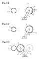
- the transfer drum 12 is thus constructed. Steps of work for forming a ply 4, i.e., a tire structural member, on the forming drum 11 will be described with reference to Figs. 3 and 4.
- the transfer drum 12 is set apart from the forming drum 11.
- An inner liner 1 is wound around the forming drum 11, while the strips 2 of a predetermined length are arranged successively on the circumference of the transfer drum 12 in a circumferential direction with the side edges of the adjacent strips 2 overlapping each other.
- the strips 2 thus arranged are attracted to the circumference of the transfer drum 12 by suction exerted thereon by the vacuum mechanism 20.
- the strips 2 are formed by cutting a long, band of a predetermined width of ⁇ D/n (n is an integer) formed by coating a plurality of cords with rubber by an extrusion process in a predetermined length (section width).
- the strips 2 are fed successively from a predetermined position onto the intermittently turned transfer drum 12 so that the side edges of the adjacent strips 2 overlap each other.
- the distance between the partition disks 22 of the vacuum mechanism 20 is adjusted beforehand to the section width of the strips 2 to form the vacuum chamber 25 properly.
- the vacuum mechanism 20 attracts the strips 2 to the transfer drum 12 by suction, the strips 2 are not dislocated, are able to retain their shapes, and a high bonding accuracy can be insured.
- the n strips 2 of ⁇ D/n in width are applied successively to the transfer drum 12 to form the band-shaped member 3 of a predetermined length substantially equal to the circumference ⁇ D of the forming drum 11 and a width equal to the section width is formed on the transfer drum 12 as shown in Fig. 3-2.
- the swing arms 14 are turned to move the transfer drum 12 toward the forming drum 11 so that the leading end of the band-shaped member 3 is held between the drums 11 and 12 as shown in Fig. 3-3.
- the forming drums 11 and the transfer drum 12 are turned in opposite directions, respectively, to transfer the band-shaped member 3 from the transfer drum 12 to the forming drum 11 as shown in Fig. 4-1.
- the band-shaped member 3 can be transferred from the transfer drum 12 to the forming drum 11 and can be set on the forming drum 11 in a very high setting accuracy.
- the band-shaped member 3 is wound around the inner liner 1 wound around the forming drum 11 so as to cover the inner liner 1 entirely as shown in Fig. 4-2 because the length of the band-shaped member 3 is substantially equal to the circumference ⁇ D of the forming drum 11.
- the leading and the trailing end of the band-shaped member 3 are bonded together to form the ply 4.
- the band-shaped member can be transferred from the transfer drum 12 to the forming drum 11 and can be set on the forming drum 11 in a high setting accuracy, the ply 4 has a high quality.
- the swingable transfer drum 12 having a cylindrical shape is excellent in space efficiency, simple in construction and capable of reducing cost.
- the transfer drum may be translated, and the forming drum may be moved toward and away from the transfer drum.
- tire structural members such as belts
- forming work can be carried out while the transfer drum 12 is separated from the forming drum 11 after the ply 4 has been formed on the forming drum, and then strips 2 are applied again to the transfer drum 12. and hence working efficiency is excellent.
- the transfer drum 12 is provided with the vacuum mechanism 20 to hold the ply 4 on the transfer drum 12 by suction in the foregoing embodiment. If the ply includes embedded steel cords, electromagnets may be arranged on the inner circumference of the transfer drum and the ply may be attracted to the transfer drum by magnetism
- the ply can be easily separated from the transfer drum by stopping the supply of current to the electromagnets.
- the transfer drum does not need to be a cylindrical drum; a transfer drum having the shape of a polygonal prism may be used.
- the inner liner may be transferred from the transfer drum 12 to the forming drum 11.
- the forming drum may be provided with a vacuum mechanism or electromagnets, and the ply and such transferred to the forming drum may be held on the forming drum by suction or magnetism.
Landscapes
- Engineering & Computer Science (AREA)
- Textile Engineering (AREA)
- Mechanical Engineering (AREA)
- Tyre Moulding (AREA)
- Treatment Of Fiber Materials (AREA)
Abstract
Description
Claims (8)
- A tire structural member forming method comprising the steps of:applying a band-shaped member of a predetermined length and a predetermined width to a transfer drum;moving the transfer drum holding the band-shaped member relative and close to a forming drum of a diameter smaller than that of the transfer drum so that the leading end of the band-shaped member is held between the transfer drum and the forming drum;turning the transfer drum and the forming drum in opposite directions, respectively, at the same surface speed to transfer the band-shaped member from the transfer drum to the forming drum; andbonding together the leading and the trailing end of the band-shaped member wound around the forming drum to form a tire structural member on the forming drum.
- The tire structural member forming method according to claim 1, wherein the strips are held on the transfer drum by suction.
- The tire structural member forming method according to claim 1, wherein the transfer drum is finished by a surface treatment such that the band-shaped member applied to the transfer drum can be easily separated from the transfer drum.
- The tire structural member forming method according to claim 1, wherein the transfer drum is moved toward and away from the forming drum by swinging or translation.
- A tire structural member forming method comprising the steps of:cutting a long band of a predetermined width into successive strips of a predetermined length;forming a band-shaped member of a predetermined length substantially equal to the circumference of a forming drum by applying a predetermined number of the strips to a transfer drum of a diameter greater than that of the forming drum in a circumferential arrangement with side edges of adjacent strips overlapping each other;bringing the transfer drum holding the band-shaped member relative and close to the forming drum to hold the leading end of the band-shaped member between the transfer drum and the forming drum;transferring the band-shaped member from the transfer drum to the forming drum by turning the transfer drum and the forming drum in the opposite directions, respectively, at the same surface speed; andforming a tire structural member on the forming drum by bonding together the leading and the trailing end of the band-shaped member transferred to the forming drum.
- The tire structural member forming method according to claim 5, wherein the strips are held on the transfer drum by suction.
- The tire structural member forming method according to claim 5, wherein the transfer drum is finished by a surface treatment such that the band-shaped member applied to the transfer drum can be easily separated from the transfer drum.
- The tire structural member forming method according to claim 5, wherein the transfer drum is moved toward and away from the forming drum by swinging or translation.
Applications Claiming Priority (3)
| Application Number | Priority Date | Filing Date | Title |
|---|---|---|---|
| JP2001184260 | 2001-06-19 | ||
| JP2001184260 | 2001-06-19 | ||
| PCT/JP2002/006043 WO2002102579A1 (en) | 2001-06-19 | 2002-06-18 | Method of forming tire component member |
Publications (3)
| Publication Number | Publication Date |
|---|---|
| EP1410898A1 true EP1410898A1 (en) | 2004-04-21 |
| EP1410898A4 EP1410898A4 (en) | 2004-09-29 |
| EP1410898B1 EP1410898B1 (en) | 2006-06-21 |
Family
ID=19024052
Family Applications (1)
| Application Number | Title | Priority Date | Filing Date |
|---|---|---|---|
| EP02738745A Expired - Lifetime EP1410898B1 (en) | 2001-06-19 | 2002-06-18 | Method of forming tire component member |
Country Status (7)
| Country | Link |
|---|---|
| US (1) | US7235147B2 (en) |
| EP (1) | EP1410898B1 (en) |
| JP (1) | JP4316372B2 (en) |
| CN (1) | CN100526060C (en) |
| DE (1) | DE60212643T2 (en) |
| ES (1) | ES2266510T3 (en) |
| WO (1) | WO2002102579A1 (en) |
Cited By (3)
| Publication number | Priority date | Publication date | Assignee | Title |
|---|---|---|---|---|
| US8980030B2 (en) | 2008-04-23 | 2015-03-17 | Michelin Recherche Et Technique S.A. | Method and apparatus for forming a multi-layered tire component |
| JP2016531767A (en) * | 2013-10-02 | 2016-10-13 | ヴェーエムイー ホーランド ベー. ヴェー.Vmi Holland B. V. | Method for picking up and placing a tire part on a transfer drum |
| DE102004037738B4 (en) * | 2004-08-04 | 2020-12-17 | Continental Reifen Deutschland Gmbh | Method and device for placing pre-cut material strips for tire components on a tire building drum |
Families Citing this family (13)
| Publication number | Priority date | Publication date | Assignee | Title |
|---|---|---|---|---|
| WO2005049305A1 (en) * | 2003-11-20 | 2005-06-02 | Bridgestone, Corporation | Transferring device for sheet member |
| JP4402480B2 (en) * | 2004-03-02 | 2010-01-20 | 株式会社ブリヂストン | Transfer drum manufacturing method and transfer drum |
| FR2879957B1 (en) * | 2004-12-24 | 2007-03-02 | Michelin Soc Tech | COMBINATION DRUM OF FRAME OF REINFORCEMENT |
| US20100288423A1 (en) * | 2006-06-29 | 2010-11-18 | Pirelli Tyre S.P.A. | Process for manufacturing tyres for vehicle wheels |
| EP1985561A1 (en) * | 2007-04-23 | 2008-10-29 | Harburg-Freundenberger Maschinenbau GmbH | Method and device for handling strip-like workpieces |
| EP2365904B1 (en) | 2008-12-05 | 2014-02-12 | MICHELIN Recherche et Technique S.A. | Method and apparatus for forming a tire component upon an axially tapered surface |
| JP5557838B2 (en) * | 2009-07-15 | 2014-07-23 | 株式会社ブリヂストン | Tire component manufacturing apparatus and manufacturing method |
| FR2967938A1 (en) * | 2010-11-30 | 2012-06-01 | Michelin Soc Tech | METHOD OF TRANSFERRING A COMPONENT FROM A PNEUMATIC BRAKE |
| NL2007058C2 (en) * | 2011-07-06 | 2013-01-08 | Vmi Holland Bv | COMPOSITION AND METHOD FOR MANUFACTURING A GREEN BAND |
| JP6196930B2 (en) * | 2014-04-15 | 2017-09-13 | 東洋ゴム工業株式会社 | Rubber member conveying method and conveying device |
| JP5968969B2 (en) * | 2014-09-24 | 2016-08-10 | 株式会社ブリヂストン | Cylindrical member manufacturing apparatus and manufacturing method |
| EP3697605B1 (en) * | 2017-10-16 | 2021-07-21 | Compagnie Générale des Etablissements Michelin | Transfer and posing of a semi-finished product destined for use in tire production |
| JP6970613B2 (en) * | 2017-12-28 | 2021-11-24 | Toyo Tire株式会社 | Tire component manufacturing method and tire component manufacturing device |
Family Cites Families (19)
| Publication number | Priority date | Publication date | Assignee | Title |
|---|---|---|---|---|
| US2918105A (en) * | 1954-11-24 | 1959-12-22 | Cleveland Trust Co | Servicing machine for pneumatic tire building machinery |
| US2988131A (en) * | 1956-04-23 | 1961-06-13 | Cleveland Trust Co | Magnetic ply holder |
| GB1010597A (en) * | 1961-09-01 | 1965-11-24 | Dunlop Rubber Co | Improvements in or relating to the production of pneumatic tyres |
| FR2141480B1 (en) * | 1971-06-03 | 1973-06-29 | Uniroyal | |
| FR2151701A5 (en) * | 1971-09-09 | 1973-04-20 | Uniroyal | |
| US3826297A (en) | 1972-10-26 | 1974-07-30 | Steelastic Co | Radial tire carcass |
| US3844871A (en) * | 1973-02-05 | 1974-10-29 | Uniroyal Inc | Tire building machine |
| JPS5316837B2 (en) * | 1974-12-27 | 1978-06-03 | ||
| US4090909A (en) * | 1976-08-20 | 1978-05-23 | The Goodyear Tire & Rubber Company | Tire band building drum |
| JPS5462285A (en) * | 1977-10-28 | 1979-05-19 | Bridgestone Corp | Reinforcing material for rubber and its preparation |
| US4267104A (en) * | 1979-06-14 | 1981-05-12 | Eastman Kodak Company | Dyes from selected substituted aniline diazo components and aniline couplers containing sulfate ester groups |
| US4276104A (en) * | 1980-01-11 | 1981-06-30 | The Goodyear Tire & Rubber Company | Transfer drum application of narrow strip components to a tire being built on a tire building drum |
| GB8312994D0 (en) * | 1983-05-11 | 1983-06-15 | Dunlop Ltd | Tyre building machinery |
| US4891082A (en) * | 1986-11-26 | 1990-01-02 | The Goodyear Tire & Rubber Company | Transfer roll system |
| JP3124560B2 (en) * | 1990-12-28 | 2001-01-15 | 株式会社ブリヂストン | Ply member molding method |
| EP0958913B1 (en) * | 1997-11-10 | 2003-06-11 | The Yokohama Rubber Co., Ltd. | Apparatus and method for aligning and splicing strip members |
| JP2001009928A (en) * | 1999-07-01 | 2001-01-16 | Mitsubishi Heavy Ind Ltd | Belt sticking device for large vehicle tires |
| JP4326112B2 (en) * | 2000-04-10 | 2009-09-02 | 株式会社ブリヂストン | Manufacturing method of tire carcass |
| US20030051794A1 (en) * | 2001-01-12 | 2003-03-20 | Nobuyuki Suda | Tire construction member producing method and device therefor |
-
2002
- 2002-06-18 ES ES02738745T patent/ES2266510T3/en not_active Expired - Lifetime
- 2002-06-18 DE DE60212643T patent/DE60212643T2/en not_active Expired - Lifetime
- 2002-06-18 EP EP02738745A patent/EP1410898B1/en not_active Expired - Lifetime
- 2002-06-18 CN CN02802104.5A patent/CN100526060C/en not_active Expired - Fee Related
- 2002-06-18 US US10/343,454 patent/US7235147B2/en not_active Expired - Lifetime
- 2002-06-18 JP JP2003505144A patent/JP4316372B2/en not_active Expired - Fee Related
- 2002-06-18 WO PCT/JP2002/006043 patent/WO2002102579A1/en not_active Ceased
Cited By (3)
| Publication number | Priority date | Publication date | Assignee | Title |
|---|---|---|---|---|
| DE102004037738B4 (en) * | 2004-08-04 | 2020-12-17 | Continental Reifen Deutschland Gmbh | Method and device for placing pre-cut material strips for tire components on a tire building drum |
| US8980030B2 (en) | 2008-04-23 | 2015-03-17 | Michelin Recherche Et Technique S.A. | Method and apparatus for forming a multi-layered tire component |
| JP2016531767A (en) * | 2013-10-02 | 2016-10-13 | ヴェーエムイー ホーランド ベー. ヴェー.Vmi Holland B. V. | Method for picking up and placing a tire part on a transfer drum |
Also Published As
| Publication number | Publication date |
|---|---|
| WO2002102579A1 (en) | 2002-12-27 |
| US20030168152A1 (en) | 2003-09-11 |
| JP4316372B2 (en) | 2009-08-19 |
| CN100526060C (en) | 2009-08-12 |
| JPWO2002102579A1 (en) | 2004-09-30 |
| US7235147B2 (en) | 2007-06-26 |
| EP1410898B1 (en) | 2006-06-21 |
| EP1410898A4 (en) | 2004-09-29 |
| DE60212643D1 (en) | 2006-08-03 |
| CN1463222A (en) | 2003-12-24 |
| DE60212643T2 (en) | 2007-07-05 |
| ES2266510T3 (en) | 2007-03-01 |
Similar Documents
| Publication | Publication Date | Title |
|---|---|---|
| US7235147B2 (en) | Method of forming tire component member | |
| US5203938A (en) | Method and apparatus for forming an apex filler and/or applying an apex filler to a bead ring sub-assembly | |
| US6974522B2 (en) | Method and apparatus for mounting a plurality of magnet segments on a back ring | |
| EP0326365B1 (en) | Cylindrical member transfer apparatus and tire building machine having the same | |
| KR0185749B1 (en) | Method for manufacturing bead assembly for tires and apparatus therefor | |
| CN215248567U (en) | Applicator rollers and tire component feeders for applying strips to drums | |
| JP4801663B2 (en) | Formation of tire bead assembly | |
| JP2017213702A (en) | Joining method of band-shaped member and device | |
| US20200198275A1 (en) | Apparatus for manufacturing green tire and method for manufacturing green tire | |
| JP2008221750A (en) | Method and device for treating cylindrical rubber material | |
| EP0214079A2 (en) | Apparatus and method for storing and feeding tire beads | |
| EP0719632B1 (en) | Single-stage tire forming system | |
| US11130301B2 (en) | Device and method for manufacturing cylindrical member | |
| JP4278494B2 (en) | Method and apparatus for transferring a belt-shaped rubber member | |
| JPH0699518A (en) | Method and apparatus for molding tire bead composite structure | |
| JP4306869B2 (en) | Label expansion mechanism | |
| JP3558356B2 (en) | Conveyor for ophthalmic lens material | |
| JP2001009928A (en) | Belt sticking device for large vehicle tires | |
| JPH10113996A (en) | Single-stage tire building equipment | |
| JP3860906B2 (en) | Mechanical turn-up method and mechanical turn-up device for band transfer device | |
| JP3799149B2 (en) | Tire molding method and tire molding apparatus | |
| JPH06270288A (en) | Apparatus for holding and transferring raw tire intermediate product | |
| JPH07186299A (en) | Method for forming belt / tread annular body for radial tire | |
| JP2006044183A (en) | Bead feeding method and device | |
| JPH06126858A (en) | Method and device for taking out and transferring a band-shaped member |
Legal Events
| Date | Code | Title | Description |
|---|---|---|---|
| PUAI | Public reference made under article 153(3) epc to a published international application that has entered the european phase |
Free format text: ORIGINAL CODE: 0009012 |
|
| 17P | Request for examination filed |
Effective date: 20030218 |
|
| AK | Designated contracting states |
Kind code of ref document: A1 Designated state(s): AT BE CH CY DE DK ES FI FR GB GR IE IT LI LU MC NL PT SE TR |
|
| A4 | Supplementary search report drawn up and despatched |
Effective date: 20040813 |
|
| RIC1 | Information provided on ipc code assigned before grant |
Ipc: 7B 29D 30/30 B Ipc: 7B 29D 30/08 A |
|
| 17Q | First examination report despatched |
Effective date: 20050616 |
|
| GRAP | Despatch of communication of intention to grant a patent |
Free format text: ORIGINAL CODE: EPIDOSNIGR1 |
|
| RBV | Designated contracting states (corrected) |
Designated state(s): DE ES FR GB IT |
|
| GRAS | Grant fee paid |
Free format text: ORIGINAL CODE: EPIDOSNIGR3 |
|
| GRAA | (expected) grant |
Free format text: ORIGINAL CODE: 0009210 |
|
| AK | Designated contracting states |
Kind code of ref document: B1 Designated state(s): DE ES FR GB IT |
|
| REG | Reference to a national code |
Ref country code: GB Ref legal event code: FG4D |
|
| REF | Corresponds to: |
Ref document number: 60212643 Country of ref document: DE Date of ref document: 20060803 Kind code of ref document: P |
|
| ET | Fr: translation filed | ||
| REG | Reference to a national code |
Ref country code: ES Ref legal event code: FG2A Ref document number: 2266510 Country of ref document: ES Kind code of ref document: T3 |
|
| PLBE | No opposition filed within time limit |
Free format text: ORIGINAL CODE: 0009261 |
|
| STAA | Information on the status of an ep patent application or granted ep patent |
Free format text: STATUS: NO OPPOSITION FILED WITHIN TIME LIMIT |
|
| 26N | No opposition filed |
Effective date: 20070322 |
|
| PGFP | Annual fee paid to national office [announced via postgrant information from national office to epo] |
Ref country code: FR Payment date: 20100709 Year of fee payment: 9 |
|
| PGFP | Annual fee paid to national office [announced via postgrant information from national office to epo] |
Ref country code: IT Payment date: 20100616 Year of fee payment: 9 |
|
| PGFP | Annual fee paid to national office [announced via postgrant information from national office to epo] |
Ref country code: ES Payment date: 20100630 Year of fee payment: 9 |
|
| PGFP | Annual fee paid to national office [announced via postgrant information from national office to epo] |
Ref country code: DE Payment date: 20100616 Year of fee payment: 9 Ref country code: GB Payment date: 20100616 Year of fee payment: 9 |
|
| GBPC | Gb: european patent ceased through non-payment of renewal fee |
Effective date: 20110618 |
|
| PG25 | Lapsed in a contracting state [announced via postgrant information from national office to epo] |
Ref country code: IT Free format text: LAPSE BECAUSE OF NON-PAYMENT OF DUE FEES Effective date: 20110618 |
|
| REG | Reference to a national code |
Ref country code: FR Ref legal event code: ST Effective date: 20120229 |
|
| REG | Reference to a national code |
Ref country code: DE Ref legal event code: R119 Ref document number: 60212643 Country of ref document: DE Effective date: 20120103 |
|
| PG25 | Lapsed in a contracting state [announced via postgrant information from national office to epo] |
Ref country code: FR Free format text: LAPSE BECAUSE OF NON-PAYMENT OF DUE FEES Effective date: 20110630 Ref country code: DE Free format text: LAPSE BECAUSE OF NON-PAYMENT OF DUE FEES Effective date: 20120103 |
|
| PG25 | Lapsed in a contracting state [announced via postgrant information from national office to epo] |
Ref country code: GB Free format text: LAPSE BECAUSE OF NON-PAYMENT OF DUE FEES Effective date: 20110618 |
|
| REG | Reference to a national code |
Ref country code: ES Ref legal event code: FD2A Effective date: 20121116 |
|
| PG25 | Lapsed in a contracting state [announced via postgrant information from national office to epo] |
Ref country code: ES Free format text: LAPSE BECAUSE OF NON-PAYMENT OF DUE FEES Effective date: 20110619 |