EP0214079A2 - Apparatus and method for storing and feeding tire beads - Google Patents
Apparatus and method for storing and feeding tire beads Download PDFInfo
- Publication number
- EP0214079A2 EP0214079A2 EP86630120A EP86630120A EP0214079A2 EP 0214079 A2 EP0214079 A2 EP 0214079A2 EP 86630120 A EP86630120 A EP 86630120A EP 86630120 A EP86630120 A EP 86630120A EP 0214079 A2 EP0214079 A2 EP 0214079A2
- Authority
- EP
- European Patent Office
- Prior art keywords
- beads
- conveyors
- support member
- assembly
- conveyor
- Prior art date
- Legal status (The legal status is an assumption and is not a legal conclusion. Google has not performed a legal analysis and makes no representation as to the accuracy of the status listed.)
- Granted
Links
Images


Classifications
-
- B—PERFORMING OPERATIONS; TRANSPORTING
- B29—WORKING OF PLASTICS; WORKING OF SUBSTANCES IN A PLASTIC STATE IN GENERAL
- B29D—PRODUCING PARTICULAR ARTICLES FROM PLASTICS OR FROM SUBSTANCES IN A PLASTIC STATE
- B29D30/00—Producing pneumatic or solid tyres or parts thereof
- B29D30/0016—Handling tyres or parts thereof, e.g. supplying, storing, conveying
- B29D2030/0044—Handling tyre beads, e.g., storing, transporting, transferring and supplying to the toroidal support or to the drum
-
- Y—GENERAL TAGGING OF NEW TECHNOLOGICAL DEVELOPMENTS; GENERAL TAGGING OF CROSS-SECTIONAL TECHNOLOGIES SPANNING OVER SEVERAL SECTIONS OF THE IPC; TECHNICAL SUBJECTS COVERED BY FORMER USPC CROSS-REFERENCE ART COLLECTIONS [XRACs] AND DIGESTS
- Y10—TECHNICAL SUBJECTS COVERED BY FORMER USPC
- Y10S—TECHNICAL SUBJECTS COVERED BY FORMER USPC CROSS-REFERENCE ART COLLECTIONS [XRACs] AND DIGESTS
- Y10S414/00—Material or article handling
- Y10S414/123—Hollow cylinder handlers
-
- Y—GENERAL TAGGING OF NEW TECHNOLOGICAL DEVELOPMENTS; GENERAL TAGGING OF CROSS-SECTIONAL TECHNOLOGIES SPANNING OVER SEVERAL SECTIONS OF THE IPC; TECHNICAL SUBJECTS COVERED BY FORMER USPC CROSS-REFERENCE ART COLLECTIONS [XRACs] AND DIGESTS
- Y10—TECHNICAL SUBJECTS COVERED BY FORMER USPC
- Y10T—TECHNICAL SUBJECTS COVERED BY FORMER US CLASSIFICATION
- Y10T156/00—Adhesive bonding and miscellaneous chemical manufacture
- Y10T156/17—Surface bonding means and/or assemblymeans with work feeding or handling means
- Y10T156/1702—For plural parts or plural areas of single part
- Y10T156/1744—Means bringing discrete articles into assembled relationship
Definitions
- This invention relates generally to building pneumatic tires wherein annular beads are made by winding wire into bead rings which are then transported to a tire building machine for assembly with the plies and other tire components into a green tire. The green tire may then be placed in a mold and vulcanized.
- the beads have been supported on horizontal rods which have rotatable vanes to separate the beads and are reciprocable for manipulating the beads especially in applications where different size beads are applied.
- the apparatus and process of this invention is directed toward conveying the beads to the tire bead storing and feeding apparatus in a rack which supports the beads in a separated condition and then positioning the beads in the separated condition over continuous conveyors of the loading apparatus in which the conveyors are expanded to grip the beads and hold them in the separated condition so that the rack can be removed.
- the conveyors are then actuated for simultaneous movement toward one end of the conveyors to deliver the beads to a bead transfer apparatus while at the same time maintaining the beads in the spaced condition.
- Means are also provided to adjust the apparatus to accommodate a range of bead sizes and to insure the feeding of one bead at a time.
- appartus for storing and feeding annular beads comprising:
- a method of storing and feeding annular beads supplied to a storing and feeding apparatus in a separated condition comprising:
- an apparatus 10 for storing and feeding annular beads 12 which includes a turret 14 swiveled in a stand 16 for mounting on the floor.
- a conveyor assembly 18 is mounted on the turret 14 and has a plurality of continuous conveyors 20 positioned around a central axis 22-22 of the conveyor assembly for radial movement thereof.
- a motor 24 for driving the conveyors 20 may be mounted on the turret 14 and controlled by suitably manual or automatic controls 26.
- the annular beads 12 be supplied to the storing and feeding apparatus 10 in a separated condition and this may be accomplished in accordance with the method of this invention by placing the beads in a rack 28 having a generally U-shaped cross section and separators between grooves for receiving the beads 12 after they are assembled on a bead crimping or jamming apparatus and then holding the beads in a separated condition. This is especially important with beads 12 which are not wrapped and have a tacky surface.
- the loaded rack 28 is transported to the apparatus 10 for storing and feeding the beads 12 from the bead crimping or jamming apparatus and then the rack is moved axially along the conveyor assembly 18 to place the beads around the conveyor assembly as shown in Fig 2.
- the continuous conveyors 20 are then moved radially outward of the central axis 22-22 into gripping engagement with the radially inner surfaces of the beads 12 to maintain the beads in the separated positions relative to one another.
- the rack 28 may then be moved radially of the central axis 22-22 away from the conveyor assembly 18. If desired, the turret 14 may be turned to align the conveyor assembly 18 with a bead transfer ring or other bead transfer apparatus for receiving the beads 12 from the bead storing and feeding apparatus 10.
- the continuous conveyors 20 may then be simultaneously and intermittently operated to move the beads 12 toward an open end 30 of the conveyor assembly 18 to feed one bead at a time to a suitable bead transfer device for carrying the bead to a tire building machine and positioning the bead on a bead ring of the tire building drum.
- a central support member for the conveyor assembly such as cylindrical spindle 32 has a flanged plate 34 at a closed end for mounting on the turret 14.
- Radially extending slide members such as radially extending rods 38 are mounted on the flanged plate 34 at each side of each belt housing 36 for slidable engagement with collars 40 on supporting brackets 42 mounted on the housing.
- Each belt housing 36 is moved from an expanded position, shown in Fig 4, to a contracted position, shown in Fig 2, by connecting links 44 and 46 pivotally connected to each belt housing at pivot points 48 and 50 and to pivotal connections 52 and 54 mounted on slide members 56 and 58, respectively, slidably mounted on the outer surface of the cylindrical spindle 32.
- the slide members 56 and 58 include piston and cylinder assemblies 60 and 62 which are connected to stop members 64 and 66 by piston rods 68 and 70, respectively.
- the slide members 56 and 58 may be moved toward the stop members 64 and 66 causing the pivotal connections 52 and 54 to move the inner ends of the links 44 and 46 together and thereby retract the belt housing 36 to a position of lesser diameter than that shown in Fig 4. This is desirable for decreasing the diameter of the conveyor assembly 18 to receive the beads 12 from the rack 28 as shown in Fig 2.
- the stop members 64 and 66 are adjustably mounted on the spindle 32.
- the following description is directed to stop member 64; however, the constuction of stop member 66 is the same except for the differences which will be explained hereinafter.
- a nut 72 is positioned within the spindle 32 and is connected to the slide member 64 by pins 74 extending through slots 76 in the spindle.
- a shaft 78 is rotatably mounted in the spindle 32 on suitable bearings 80 and is connected to a crank 82 at the open end 30 of the conveyor assembly 18. At the slide member 64, the shaft 78 is in threaded engagement with the nut 72 for moving the slide member upon rotation of the shaft by the crank 82.
- the threaded connection of the shaft 78 with the nut 72 at the slide member 66 is of opposite hand to the threaded connection at the slide memebr 64 so that upon turning the shaft in one direction the slide member 64 and slide member 66 will be moved toward each other and upon rotation of the shaft in the opposite direction the slide members will be moved away from each other.
- This adjustment provides for controlling the expanded position of the belt housings 36 so that the apparatus 10 can be used for different diameter beads 12.
- crank 82 is located adjacent an end plate 84 bolted to the spindle 32 and has a threaded lock pin 86 engageable with circumferentially spaced holes 88 in the end plate for locking the shaft 78 in the desired position after adjustment of the stop member 64 and 66 for a particular size of bead 12.
- the axial position of shaft 78 relative to the spindle 32 is maintained by alignment means such as threaded clamp collars 89 at each side of the bearing 80 as shown in Fig. 8.
- Axial adjustment of the shaft 78 may be desirable to align each belt housing 36 and level each conveyor 20. This is done by loosening the threaded clamp collars 89 and rotating them so that the shaft 78 can be shifted axially in the bearing 80 the desired amount. The clamp collars 89 are then moved to provide a snug fit against the bearing 80 after which they are tightened on the shaft 78.
- each belt housing 36 carries a timing belt 90 having a belt path extending over idler pulleys 92 and 94 rotatably mounted on shafts 96 and 98, respectively, supported at each end of the belt housing 36.
- the belt path of the timing belt 90 also extends around take-up pulleys 100 spring mounted on the housing 36.
- the path of the timing belt 90 also extends around a drive pulley 102 mounted on a shaft 104 which is rotatably supported on the spindle 32.
- a driven sprocket is fastened to the drive pulley 102 and connected to a drive sprocket 106 by a chain 108.
- the drive sprocket 106 is rotatably mounted on a shaft 110 supported by the spindle 32 and is attached to suitable gearing such as driven worm gear 112 having threads in meshing engagement with a worm thread of drive gear 114 on a drive shaft 116 rotatably mounted in the spindle and extending through the turret 14 directly to the motor 24 or to the transmission of the motor for rotating the worm drive gear upon rotation of the drive shaft.
- Spiral bevel gears may also provide suitable gearing for certain applications.
- the driven worm gear 112 for each belt housing 36 is rotated causing the timing belt 90 of each belt housing to move simultaneously and carry the beads 12 in the separated condition along the conveyor assembly 18.
- the controls 26 for the motor 24 may be designed in a manner well known in the art to rotate the shaft 116 a predetermined number of revolutions so as to simultaneously move the beads 12 a predetermined distance to feed one bead at a time from the apparatus 10 at the open end 30.
- a radially movable stop plate assembly 118 may be mounted on the end plate 84 of the conveyor assembly 18.
- Each stop plate assembly 118 has a housing 120 containing a piston and cylinder assembly 122 with a piston connected to a stop plate 124 so that when air is communicated to the cylinder of the piston and cylinder assembly, the stop plate will be moved radially outward to a position in the path of the beads 12 on the conveyors 20.
- the piston and cylinder assembly 122 is actuated after the endmost bead 12 has been moved to a position for transfer to a suitable bead transfer device and will retain the second endmost bead on the conveyor assembly 18.
Landscapes
- Engineering & Computer Science (AREA)
- Mechanical Engineering (AREA)
- Tyre Moulding (AREA)
- Stacking Of Articles And Auxiliary Devices (AREA)
- De-Stacking Of Articles (AREA)
Abstract
Description
- This invention relates generally to building pneumatic tires wherein annular beads are made by winding wire into bead rings which are then transported to a tire building machine for assembly with the plies and other tire components into a green tire. The green tire may then be placed in a mold and vulcanized.
- In the manufacture of tires, it is important that the beads be made with precision and then stored and transported without distortion. Heretofore one bead feeding apparatus has been proposed in which several continuous vertical conveyor chains have been used for supporting beads on clips fastened to the vertical chains. In another feeding apparatus the beads have been stacked on a vertical drum and then raised by spider arms extending through slots in the drum to lift the beads to the top of the drum where the beads are lifted off the stack by a magnetic bead transfer device. Another bead feeding apparatus has a horizontal drum with radially movable sleeve sections at the ends for retracting to receive a stack of beads and expanding to hold the beads. Then at each end a ring is pushed by a sleeve section to move the stack toward the end where the beads are fed individually to the bead transfer member. In still another bead feeding apparatus, the beads have been supported on horizontal rods which have rotatable vanes to separate the beads and are reciprocable for manipulating the beads especially in applications where different size beads are applied.
- In the manufacture of certain bead rings it has been found that it is important to handle the beads separately so that they do not stick together. This is especially true of beads which are jammed or crimped in accordance with the disclosure in U.S. Patent No. 4,452,660 dated June 5, 1984 of Davis et al and allowed Divisional Patent Application Serial No. 593,561 filed March 26, 1984 assigned to the Assignee of this application. The beads made with this equipment and process are not wrapped and are preferably not stacked or positioned close together. Accordingly, the apparatus and process of this invention is directed toward conveying the beads to the tire bead storing and feeding apparatus in a rack which supports the beads in a separated condition and then positioning the beads in the separated condition over continuous conveyors of the loading apparatus in which the conveyors are expanded to grip the beads and hold them in the separated condition so that the rack can be removed. The conveyors are then actuated for simultaneous movement toward one end of the conveyors to deliver the beads to a bead transfer apparatus while at the same time maintaining the beads in the spaced condition. Means are also provided to adjust the apparatus to accommodate a range of bead sizes and to insure the feeding of one bead at a time.
- In accordance with one aspect of the invention there is provided appartus for storing and feeding annular beads comprising:
- (a) a conveyor assembly having a plurality of continuous conveyors positioned around a central axis and extending in an axial direction for engaging radially inner surfaces of beads placed around the conveyor assembly;
- (b) means to move each of the conveyors radially outward of the central axis for urging each of the conveyors into gripping engagement with the beads; and
- (c) means for driving the continuous conveyors simultaneously and intermittently toward one end of the assembly to feed the beads one at a time.
- In accordance with another aspect of the invention there is provided a method of storing and feeding annular beads supplied to a storing and feeding apparatus in a separated condition comprising:
- (a) placing a plurality of beads around a conveyor asembly having a plurality of continuous conveyors positioned around a central axis and extending in an axial direction for engaging radially inner surfaces of the beads.;
- (b) moving the continuous conveyors radially outward of the central axis into gripping engagement with the beads to maintain the separated positions of the beads relative to one another;
- (c) actuating all the continuous conveyors simultaneously and intermittently to move the beads toward one end of the assembly and feed one bead at a time.
- To acquaint persons skilled in the arts most closely related to the present invention, a certain preferred embodiment thereof illustrating a best mode now contemplated for putting the invention into practice is described herein by and with reference to the annexed drawings forming a part of the specification. The embodiment shown and described herein is illustrative and as will become apparent to those skilled in these arts can be modified in numerous ways within the spirit and scope of the invention defined in the claims hereof.
- In the drawings:
- Fig 1 is a schematic side elevation of an apparatus embodying the invention showing the beads supported in a bead rack before placing on the conveyor assembly.
- Fig 2 is an elevation like Fig 1 showing the beads placed over the conveyor assembly after axial movement of the bead rack.
- Fig 3 is an elevation like Fig 1 showing the beads placed on the conveyor assembly and gripped by expansion of the conveyors with the rack shown after radial movement away from the conveyor assembly.
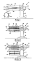
- Fig 4 is a side view, half in section of the conveyor assembly taken along the line 4-4 in Fig 5.
- Fig 5 is an end view of the conveyor assembly taken along the line 5-5 in Fig 4 with parts being broken away to show the gripping mechanism for the second bead.
- Fig 6 is a sectional view taken along the line 6-6 in Fig 4 showing a full section of the worm drive.
- Fig 7 is an enlarged full sectional view of the bead diameter adjusting mechanism taken along the line 7-7 in Fig 4.
- Fig 8 is a fragmentary sectional view of another portion of the adjusting mechanism taken along the line 8-8 in Fig 5 showing the alignment leveling adjustment.
- Referring to the drawings and especially to Figs 1, 2 and 3, an
apparatus 10 for storing and feedingannular beads 12 is shown which includes aturret 14 swiveled in astand 16 for mounting on the floor. Aconveyor assembly 18 is mounted on theturret 14 and has a plurality ofcontinuous conveyors 20 positioned around a central axis 22-22 of the conveyor assembly for radial movement thereof. Amotor 24 for driving theconveyors 20 may be mounted on theturret 14 and controlled by suitably manual orautomatic controls 26. - In operation of the apparatus, it is preferably that the
annular beads 12 be supplied to the storing and feedingapparatus 10 in a separated condition and this may be accomplished in accordance with the method of this invention by placing the beads in arack 28 having a generally U-shaped cross section and separators between grooves for receiving thebeads 12 after they are assembled on a bead crimping or jamming apparatus and then holding the beads in a separated condition. This is especially important withbeads 12 which are not wrapped and have a tacky surface. The loadedrack 28 is transported to theapparatus 10 for storing and feeding thebeads 12 from the bead crimping or jamming apparatus and then the rack is moved axially along theconveyor assembly 18 to place the beads around the conveyor assembly as shown in Fig 2. Thecontinuous conveyors 20 are then moved radially outward of the central axis 22-22 into gripping engagement with the radially inner surfaces of thebeads 12 to maintain the beads in the separated positions relative to one another. Therack 28 may then be moved radially of the central axis 22-22 away from theconveyor assembly 18. If desired, theturret 14 may be turned to align theconveyor assembly 18 with a bead transfer ring or other bead transfer apparatus for receiving thebeads 12 from the bead storing and feedingapparatus 10. Thecontinuous conveyors 20 may then be simultaneously and intermittently operated to move thebeads 12 toward anopen end 30 of theconveyor assembly 18 to feed one bead at a time to a suitable bead transfer device for carrying the bead to a tire building machine and positioning the bead on a bead ring of the tire building drum. - Referring to Figs 4 through 8, the
conveyor assembly 18 is shown in greater detail. A central support member for the conveyor assembly such ascylindrical spindle 32 has aflanged plate 34 at a closed end for mounting on theturret 14. In this embodiment, there are fourcontinuous conveyors 20, each of which has a conveyor support member orbelt housing 36. Radially extending slide members such as radially extendingrods 38 are mounted on theflanged plate 34 at each side of eachbelt housing 36 for slidable engagement withcollars 40 on supportingbrackets 42 mounted on the housing. - Each
belt housing 36 is moved from an expanded position, shown in Fig 4, to a contracted position, shown in Fig 2, by connectinglinks pivot points pivotal connections slide members 56 and 58, respectively, slidably mounted on the outer surface of thecylindrical spindle 32. Theslide members 56 and 58 include piston andcylinder assemblies members piston rods 68 and 70, respectively. By communicating air pressure to the piston and cylinder assemblies 60 and 62, theslide members 56 and 58 may be moved toward thestop members pivotal connections links belt housing 36 to a position of lesser diameter than that shown in Fig 4. This is desirable for decreasing the diameter of theconveyor assembly 18 to receive thebeads 12 from therack 28 as shown in Fig 2. - As shown in Figs 7 and 8, the
stop members spindle 32. The following description is directed to stopmember 64; however, the constuction ofstop member 66 is the same except for the differences which will be explained hereinafter. A nut 72 is positioned within thespindle 32 and is connected to theslide member 64 bypins 74 extending throughslots 76 in the spindle. Ashaft 78 is rotatably mounted in thespindle 32 onsuitable bearings 80 and is connected to acrank 82 at theopen end 30 of theconveyor assembly 18. At theslide member 64, theshaft 78 is in threaded engagement with the nut 72 for moving the slide member upon rotation of the shaft by thecrank 82. The threaded connection of theshaft 78 with the nut 72 at theslide member 66 is of opposite hand to the threaded connection at theslide memebr 64 so that upon turning the shaft in one direction theslide member 64 andslide member 66 will be moved toward each other and upon rotation of the shaft in the opposite direction the slide members will be moved away from each other. This adjustment provides for controlling the expanded position of thebelt housings 36 so that theapparatus 10 can be used fordifferent diameter beads 12. Referring to Fig 8, thecrank 82 is located adjacent anend plate 84 bolted to thespindle 32 and has a threadedlock pin 86 engageable with circumferentially spacedholes 88 in the end plate for locking theshaft 78 in the desired position after adjustment of thestop member bead 12. - The axial position of
shaft 78 relative to thespindle 32 is maintained by alignment means such as threadedclamp collars 89 at each side of thebearing 80 as shown in Fig. 8. Axial adjustment of theshaft 78 may be desirable to align eachbelt housing 36 and level eachconveyor 20. This is done by loosening the threadedclamp collars 89 and rotating them so that theshaft 78 can be shifted axially in thebearing 80 the desired amount. Theclamp collars 89 are then moved to provide a snug fit against thebearing 80 after which they are tightened on theshaft 78. - As shown in Figs 4 and 5, each
belt housing 36 carries atiming belt 90 having a belt path extending overidler pulleys shafts belt housing 36. The belt path of thetiming belt 90 also extends around take-up pulleys 100 spring mounted on thehousing 36. - The path of the
timing belt 90 also extends around adrive pulley 102 mounted on ashaft 104 which is rotatably supported on thespindle 32. A driven sprocket is fastened to the drivepulley 102 and connected to adrive sprocket 106 by achain 108. Thedrive sprocket 106, as shown in Fig 6, is rotatably mounted on ashaft 110 supported by thespindle 32 and is attached to suitable gearing such as drivenworm gear 112 having threads in meshing engagement with a worm thread ofdrive gear 114 on adrive shaft 116 rotatably mounted in the spindle and extending through theturret 14 directly to themotor 24 or to the transmission of the motor for rotating the worm drive gear upon rotation of the drive shaft. Spiral bevel gears may also provide suitable gearing for certain applications. - As shown in Fig 6, when the
drive shaft 116 is rotated the drivenworm gear 112 for eachbelt housing 36 is rotated causing thetiming belt 90 of each belt housing to move simultaneously and carry thebeads 12 in the separated condition along theconveyor assembly 18. Thecontrols 26 for themotor 24 may be designed in a manner well known in the art to rotate the shaft 116 a predetermined number of revolutions so as to simultaneously move the beads 12 a predetermined distance to feed one bead at a time from theapparatus 10 at theopen end 30. - As shown in Figs 4 and 5, between each of the
belt housings 36, a radially movablestop plate assembly 118 may be mounted on theend plate 84 of theconveyor assembly 18. Eachstop plate assembly 118 has ahousing 120 containing a piston andcylinder assembly 122 with a piston connected to astop plate 124 so that when air is communicated to the cylinder of the piston and cylinder assembly, the stop plate will be moved radially outward to a position in the path of thebeads 12 on theconveyors 20. The piston andcylinder assembly 122 is actuated after theendmost bead 12 has been moved to a position for transfer to a suitable bead transfer device and will retain the second endmost bead on theconveyor assembly 18. - While a certain representative embodiment and details have been shown for the purpose of illustrating the invention, it will be apparent to those skilled in the art that various changes and modifications may be made therein without departing form the spirit or scope of the invention.
Claims (10)
Applications Claiming Priority (2)
| Application Number | Priority Date | Filing Date | Title |
|---|---|---|---|
| US761181 | 1985-07-31 | ||
| US06/761,181 US4683020A (en) | 1985-07-31 | 1985-07-31 | Apparatus for storing and feeding tire beads |
Publications (3)
| Publication Number | Publication Date |
|---|---|
| EP0214079A2 true EP0214079A2 (en) | 1987-03-11 |
| EP0214079A3 EP0214079A3 (en) | 1988-12-14 |
| EP0214079B1 EP0214079B1 (en) | 1991-12-04 |
Family
ID=25061417
Family Applications (1)
| Application Number | Title | Priority Date | Filing Date |
|---|---|---|---|
| EP86630120A Expired - Lifetime EP0214079B1 (en) | 1985-07-31 | 1986-07-30 | Apparatus and method for storing and feeding tire beads |
Country Status (5)
| Country | Link |
|---|---|
| US (1) | US4683020A (en) |
| EP (1) | EP0214079B1 (en) |
| JP (1) | JPS6231621A (en) |
| CA (1) | CA1262922A (en) |
| DE (1) | DE3682727D1 (en) |
Cited By (2)
| Publication number | Priority date | Publication date | Assignee | Title |
|---|---|---|---|---|
| EP0283423A1 (en) * | 1987-03-17 | 1988-09-21 | The Goodyear Tire & Rubber Company | Bead crimping and handling system |
| EP4357118A1 (en) * | 2022-10-18 | 2024-04-24 | Continental Reifen Deutschland GmbH | Method for conveying raw cores and transfer member for raw cores |
Families Citing this family (12)
| Publication number | Priority date | Publication date | Assignee | Title |
|---|---|---|---|---|
| IT1189647B (en) * | 1986-04-08 | 1988-02-04 | Firestone Int Dev Spa | METHOD AND DEVICE FOR AUTOMATIC CENTERING AND FEEDING OF HEELS ON TIRE FORMING DRUM |
| US4806196A (en) * | 1987-03-17 | 1989-02-21 | The Goodyear Tire & Rubber Company | Bead crimping and handling system |
| US4995531A (en) * | 1989-06-14 | 1991-02-26 | Bridgestone/Firestone, Inc. | Ring dispenser |
| US5121680A (en) * | 1991-02-07 | 1992-06-16 | Nordberg Henry T | Tire compactor and method |
| US5152214A (en) * | 1991-10-10 | 1992-10-06 | Nordberg Henry T | Tire compacting machine |
| US5271321A (en) * | 1992-08-21 | 1993-12-21 | Nordberg Henry T | Tire compacting machine |
| US5339879A (en) * | 1993-09-14 | 1994-08-23 | Bridgestone/Firestone, Inc. | Pneumatic tire having opposite spiral oriented beads |
| US6468016B1 (en) * | 2000-01-25 | 2002-10-22 | The Goodyear Tire & Rubber Company | Method for temporary storage of endless, intermediate articles of manufacture |
| SE519772C2 (en) | 2001-08-10 | 2003-04-08 | Abb Ab | Apparatus and method of delivering items individually |
| BR112014013865B1 (en) * | 2011-12-14 | 2020-11-17 | Pirelli Tyre S.P.A. | method to control a production cycle, and, transfer apparatus |
| CN106956894A (en) * | 2017-04-30 | 2017-07-18 | 盐城易宝路轮胎有限公司 | A kind of streamline automobile tire auxiliary installation device |
| CN107285042B (en) * | 2017-06-15 | 2022-12-23 | 江西铭恒生物科技有限公司 | Rim belt type clamping and stacking equipment |
Family Cites Families (10)
| Publication number | Priority date | Publication date | Assignee | Title |
|---|---|---|---|---|
| US1379369A (en) * | 1920-05-15 | 1921-05-24 | Firestone Tire & Rubber Co | Bead-cementing apparatus |
| GB791478A (en) * | 1955-07-07 | 1958-03-05 | Nat Standard Company Ltd | Apparatus for the automatic production of closed loops of wire from wire stock |
| US2957572A (en) * | 1957-05-02 | 1960-10-25 | Ferro Corp | Multiple strand conveyor |
| US3849231A (en) * | 1970-02-11 | 1974-11-19 | W Brey | Bead mechanism |
| FR2087602A5 (en) * | 1970-05-26 | 1971-12-31 | Simon Jean | |
| JPS5116074B2 (en) * | 1972-11-09 | 1976-05-21 | ||
| US3982989A (en) * | 1974-10-25 | 1976-09-28 | Petr Fedorovich Badenkov | Apparatus for feeding and setting beads onto the assembly drum of a machine for assembling pneumatic tires |
| IT1124588B (en) * | 1979-10-09 | 1986-05-07 | Pirelli | IMPROVEMENTS IN EQUIPMENT FOR THE APPLICATION OF ELASTOMERIC FILLERS IN TIRES |
| JPS59115831A (en) * | 1982-12-23 | 1984-07-04 | Bridgestone Corp | Bead supply method |
| DE3526318A1 (en) * | 1985-08-26 | 1987-02-05 | Vni I K I Oboru Dlja Sinnoj Pr | Device for storing and feeding bead cores |
-
1985
- 1985-07-31 US US06/761,181 patent/US4683020A/en not_active Expired - Lifetime
-
1986
- 1986-07-22 JP JP61170976A patent/JPS6231621A/en active Granted
- 1986-07-23 CA CA000514490A patent/CA1262922A/en not_active Expired
- 1986-07-30 DE DE8686630120T patent/DE3682727D1/en not_active Expired - Fee Related
- 1986-07-30 EP EP86630120A patent/EP0214079B1/en not_active Expired - Lifetime
Cited By (2)
| Publication number | Priority date | Publication date | Assignee | Title |
|---|---|---|---|---|
| EP0283423A1 (en) * | 1987-03-17 | 1988-09-21 | The Goodyear Tire & Rubber Company | Bead crimping and handling system |
| EP4357118A1 (en) * | 2022-10-18 | 2024-04-24 | Continental Reifen Deutschland GmbH | Method for conveying raw cores and transfer member for raw cores |
Also Published As
| Publication number | Publication date |
|---|---|
| CA1262922A (en) | 1989-11-14 |
| JPS6231621A (en) | 1987-02-10 |
| US4683020A (en) | 1987-07-28 |
| DE3682727D1 (en) | 1992-01-16 |
| JPH0517126B2 (en) | 1993-03-08 |
| EP0214079B1 (en) | 1991-12-04 |
| EP0214079A3 (en) | 1988-12-14 |
Similar Documents
| Publication | Publication Date | Title |
|---|---|---|
| EP0214079B1 (en) | Apparatus and method for storing and feeding tire beads | |
| KR890000879B1 (en) | Tire manufacturing equipment | |
| EP0092922B1 (en) | Stretch wrapping apparatus | |
| CA1314473C (en) | Tubular sleeve handling and cut-off system | |
| EP2388155B1 (en) | Device and method for changing the rotational angle position of a pneumatic tyre on a wheel rim | |
| EP0464862B1 (en) | Tyre building machine and method | |
| EP0169162A2 (en) | Device for transferring a tire carcass band | |
| US4790719A (en) | Method for storing and feeding tire beads | |
| US5316228A (en) | Machine for winding two-pole stators | |
| JPS6353940B2 (en) | ||
| EP1410898B1 (en) | Method of forming tire component member | |
| JPH09267410A (en) | Bead forming machine and linear body winding device | |
| CN111605776A (en) | Automatic bundling equipment is used in plastic bag production | |
| US4304619A (en) | Method and apparatus for off-loading a completed uncured tire | |
| EP1264681B1 (en) | Bead holder assembly and method of holding and positioning a tire bead | |
| JPS63200936A (en) | Transfer roll system | |
| KR20200073758A (en) | Assembly apparatus for large cylinders | |
| CN117102560B (en) | Intelligent assembling and disassembling valve rod key groove positioning machining device | |
| US5990450A (en) | Rotary conveyor | |
| CN210453399U (en) | Full-automatic film covering machine | |
| CA1272113A (en) | Method and device for automatically centering and feeding beads onto a tire building drum | |
| EP0283423A1 (en) | Bead crimping and handling system | |
| EP1337303B1 (en) | Apparatus for manufacturing filter cartridges, and method of using same | |
| JPH05331787A (en) | Machine winding tubular sleeve into coil-like form and method therefor | |
| EP0280395B1 (en) | Belt manufacture |
Legal Events
| Date | Code | Title | Description |
|---|---|---|---|
| PUAI | Public reference made under article 153(3) epc to a published international application that has entered the european phase |
Free format text: ORIGINAL CODE: 0009012 |
|
| 17P | Request for examination filed |
Effective date: 19860806 |
|
| AK | Designated contracting states |
Kind code of ref document: A2 Designated state(s): DE FR GB LU NL |
|
| PUAL | Search report despatched |
Free format text: ORIGINAL CODE: 0009013 |
|
| AK | Designated contracting states |
Kind code of ref document: A3 Designated state(s): DE FR GB LU NL |
|
| 17Q | First examination report despatched |
Effective date: 19890712 |
|
| GRAA | (expected) grant |
Free format text: ORIGINAL CODE: 0009210 |
|
| AK | Designated contracting states |
Kind code of ref document: B1 Designated state(s): DE FR GB LU NL |
|
| REF | Corresponds to: |
Ref document number: 3682727 Country of ref document: DE Date of ref document: 19920116 |
|
| ET | Fr: translation filed | ||
| PLBE | No opposition filed within time limit |
Free format text: ORIGINAL CODE: 0009261 |
|
| STAA | Information on the status of an ep patent application or granted ep patent |
Free format text: STATUS: NO OPPOSITION FILED WITHIN TIME LIMIT |
|
| 26N | No opposition filed | ||
| EPTA | Lu: last paid annual fee | ||
| PGFP | Annual fee paid to national office [announced via postgrant information from national office to epo] |
Ref country code: LU Payment date: 19960801 Year of fee payment: 11 |
|
| PG25 | Lapsed in a contracting state [announced via postgrant information from national office to epo] |
Ref country code: LU Free format text: LAPSE BECAUSE OF NON-PAYMENT OF DUE FEES Effective date: 19970730 |
|
| PGFP | Annual fee paid to national office [announced via postgrant information from national office to epo] |
Ref country code: GB Payment date: 20000614 Year of fee payment: 15 |
|
| PGFP | Annual fee paid to national office [announced via postgrant information from national office to epo] |
Ref country code: NL Payment date: 20000620 Year of fee payment: 15 |
|
| PGFP | Annual fee paid to national office [announced via postgrant information from national office to epo] |
Ref country code: FR Payment date: 20000707 Year of fee payment: 15 |
|
| PGFP | Annual fee paid to national office [announced via postgrant information from national office to epo] |
Ref country code: DE Payment date: 20000727 Year of fee payment: 15 |
|
| PG25 | Lapsed in a contracting state [announced via postgrant information from national office to epo] |
Ref country code: GB Free format text: LAPSE BECAUSE OF NON-PAYMENT OF DUE FEES Effective date: 20010730 |
|
| PG25 | Lapsed in a contracting state [announced via postgrant information from national office to epo] |
Ref country code: NL Free format text: LAPSE BECAUSE OF NON-PAYMENT OF DUE FEES Effective date: 20020201 |
|
| GBPC | Gb: european patent ceased through non-payment of renewal fee |
Effective date: 20010730 |
|
| PG25 | Lapsed in a contracting state [announced via postgrant information from national office to epo] |
Ref country code: FR Free format text: LAPSE BECAUSE OF NON-PAYMENT OF DUE FEES Effective date: 20020329 |
|
| NLV4 | Nl: lapsed or anulled due to non-payment of the annual fee |
Effective date: 20020201 |
|
| PG25 | Lapsed in a contracting state [announced via postgrant information from national office to epo] |
Ref country code: DE Free format text: LAPSE BECAUSE OF NON-PAYMENT OF DUE FEES Effective date: 20020501 |
|
| REG | Reference to a national code |
Ref country code: FR Ref legal event code: ST |