EP1410867A2 - Kurzschluss-Lichtbogenschweissversorgung und automatische Schweissvorrichtung dafür - Google Patents
Kurzschluss-Lichtbogenschweissversorgung und automatische Schweissvorrichtung dafür Download PDFInfo
- Publication number
- EP1410867A2 EP1410867A2 EP03255852A EP03255852A EP1410867A2 EP 1410867 A2 EP1410867 A2 EP 1410867A2 EP 03255852 A EP03255852 A EP 03255852A EP 03255852 A EP03255852 A EP 03255852A EP 1410867 A2 EP1410867 A2 EP 1410867A2
- Authority
- EP
- European Patent Office
- Prior art keywords
- switching element
- welding
- power supply
- electrode
- signal
- Prior art date
- Legal status (The legal status is an assumption and is not a legal conclusion. Google has not performed a legal analysis and makes no representation as to the accuracy of the status listed.)
- Granted
Links
Images




Classifications
-
- B—PERFORMING OPERATIONS; TRANSPORTING
- B23—MACHINE TOOLS; METAL-WORKING NOT OTHERWISE PROVIDED FOR
- B23K—SOLDERING OR UNSOLDERING; WELDING; CLADDING OR PLATING BY SOLDERING OR WELDING; CUTTING BY APPLYING HEAT LOCALLY, e.g. FLAME CUTTING; WORKING BY LASER BEAM
- B23K9/00—Arc welding or cutting
- B23K9/09—Arrangements or circuits for arc welding with pulsed current or voltage
- B23K9/091—Arrangements or circuits for arc welding with pulsed current or voltage characterised by the circuits
- B23K9/092—Arrangements or circuits for arc welding with pulsed current or voltage characterised by the circuits characterised by the shape of the pulses produced
Definitions
- the present invention relates to a power supply used for performing short-circuiting arc welding.
- the present invention also relates to an automatic welding machine or welder utilizing such a power supply.
- the power supply of the present invention is designed to perform "necking current control” and "electrode polarity switching control", as will be discussed later.
- arc welding is widely employed in the metalworking industries for joining two or more metallic parts. Taking the automotive industry for example, an assembly of metallic pieces are welded together for constructing e.g. a framework of a car seat.
- the welded framework may have a number of coalesced joints each having a welding length of no greater than 50mm.
- a framework is constructed from pipes, reinforcing plates, etc., that may be connected together by automatic CO 2 -arc welding.
- the thickness of materials (pipes, reinforcing plates, etc.) used for making the framework may vary from 0.7mm to 2.0mm.
- the welds (that is, the coalesced joints) of the framework need to have a sufficient depth of fusion.
- CO 2 -arc welding is a short-circuiting arc welding, and spatters tend to be generated when the short-circuiting occurs and breaks. In particular, when the short-circuiting breaks, a relatively great amount of spatters tend to be generated.
- JP-B2- Heisei 4-4074 discloses a technique for preventing the occurrence of spatters.
- a welding wire (consumable electrode) is positively charged ("electrode positive" mode) for performing short-circuiting arc welding, and the welding current Iw is controlled for the purpose of reducing spatters.
- Fig. 5 shows the waveform of the welding current Iw (Graph A), and illustrates how a molten globule 1a transfers from the welding wire 1 to the base material 2 (Phases B ⁇ E).
- the short-circuiting between the welding wire 1 and the base material 2 occurs when the globule 1a formed on the welding wire 1 comes into contact with the molten pool 2a of the base material 2 (see Phase B). At this instant, the welding current Iw is decreased to reduce spatter generation.
- the welding current Iw is increased to exert a stronger electromagnetic pinching force on the molten bridging portion 2b (see Phase C). This promotes the globule transfer from the wire 1 to the base material 2.
- the molten bridging portion 2b is transformed into a constriction 2c (see Phase D).
- the welding current Iw is dropped off immediately before the regeneration of arc.
- This current-dropping process called “necking current control”, can significantly reduce the amount of spatters to be generated at the reoccurrence of arc.
- the DC output of the power supply is connected to a switching element, with a resistor connected to the switching element in parallel.
- the switching element is held in the conduction state to short-circuit the accompanying resistor.
- the switching element Upon detection of the constriction, the switching element is turned off so that the DC power supply will be inputted to the resistor.
- the welding current Iw can be decreased rapidly.
- the resistance of the molten bridging portion 2b increases. This resistance rise is reflected in the rate of the welding voltage (dv/dt) and the rate of the welding current (dR/dt).
- the above-mentioned detection of the constriction 2c can be performed by monitoring the rate dv/dt or dR/dt.
- the welding current Iw needs to be controlled precisely.
- the external characteristic of the power supply should be constant current characteristic.
- the power supply is caused to have constant potential characteristic so that the arc has a proper length.
- Figs. 6A and 6B While the above-described prior art technique contributes to the reduction of spatters, it still may suffer a drawback illustrated in Figs. 6A and 6B. Specifically, in these figures, two metal plates are about to be welded together. Each of the plates has a relatively small thickness (below 1mm , for example). Further, some unavoidable gap is present between the upper and lower plates. When the prior art welding is performed with the thin plates, the lower plate may be formed with burn through holes due to an excessive amount of heat input.
- Fig. 7 showing the waveform of a conventional welding current Iw (see JP-A- Heisei 11-226730, for example).
- the welding current Iw for the Tep period is supplied in the state of the "electrode positive", while the current Iw for the Ten period is supplied in the state of the "electrode negative.”
- T the cycle of the cycle
- Tep/(Tep+Ten) the polarity rate of the alternating welding current Iw. Accordingly, the "burn through hole” problem illustrated in Figs. 6A-6B can be avoided.
- this alternative prior art method tends to produce a great amount of spatters at the time of the occurrence and breakage of the short-circuiting between the welding wire and the base material.
- the present invention has been proposed under the circumstances described above. It is, therefore, an object of the present invention to provide a power supply for performing spatterless short-circuiting arc welding without causing burn through holes to be made even in a relatively thin base material.
- a power supply for short-circuiting arc welding comprises: a primary power circuit for output of direct voltage; a primary controller for controlling the output from the primary power circuit and feeding of a welding wire; a polarity switching circuit including both an electrode positive switching element and an electrode negative switching element for selectively supplying an arc load with either one of electrode positive and electrode negative voltages based on the direct voltage from the primary power circuit; a first unit including a first switching element and a first resistor connected to the first switching element in series, the first unit being connected in parallel to the electrode positive switching element; a second unit including a second switching element and a second resistor connected to the second switching element in series, the second unit being connected in parallel to the electrode negative switching element; a necking determination circuit for outputting a necking determination signal by determining, based on at least either one of a welding voltage variation and a welding current variation, whether a constriction occurs in a molten bridging portion extending between the
- an automatic welding machine incorporating the above-described power supply.
- the welding machine further comprises a welding robot; and a robot controller.
- the robot controller controls the movement of the welding robot and also sends welding condition setting signals to the power supply.
- the welding condition setting signals may include a polarity setting signal suitable for a welding area of the base material.
- Fig. 1 is a block diagram showing an arc welding power supply according to a first embodiment of the present invention.
- the illustrated power supply comprises the following features.
- a primary power circuit PMC converts an input alternating voltage to an output direct voltage.
- the input may be a commercially available three-phase voltage of 200V, for example.
- the primary power circuit PMC includes an inverter INV (incorporating an unillustrated rectifier for the input voltage), a high-frequency transformer INT, secondary rectifiers D2a ⁇ D2d, and a reactor WL.
- the inverter INV changes the rectified input voltage to a high-frequency alternating voltage.
- the transformer INT steps down this high-frequency voltage to a lower voltage suitable for performing the required welding operation.
- the secondary rectifiers D2a-D2d rectify the reduced alternating voltage, to output positive and negative DC voltages.
- the reactor WL smoothes the outputted DC voltages.
- the switching circuit SWP includes an "electrode positive" switching element PTR and an “electrode negative” switching element NTR.
- the "electrode positive” switching element PTR When the “electrode positive” switching element PTR is in a conductive state, the positive voltage is applied to the wire 1.
- the "electrode negative” switching element NTR When the "electrode negative” switching element NTR is in a conductive state, the negative voltage is applied to the wire 1.
- the "electrode positive” switching element PTR is connected in parallel to a combination of a switching element TR1 and a resistor R1 (connected to the switching element TR1 in series).
- the “electrode negative” switching element NTR is connected in parallel to a combination of a switching element TR2 and a resistor R2 (connected to the switching element TR2 in series).
- the welding wire 1 extends through a welding torch 4.
- the welding wire 1 is fed forward through the torch 4 by the rotation of feeding rollers 5a.
- Arcs 3 are generated between the welding wire 1 and the base material 2 in accordance with the welding voltage Vw and the welding current Iw.
- a voltage detector VD detects the welding voltage Vw to output a voltage detection signal Vd corresponding to the absolute value of the detected voltage Vw.
- a necking determiner ND determines whether a constriction occurs in the molten bridging portion extending between the welding wire 1 and the base material 2. For this determination, the necking determiner ND monitors the rate of the voltage detection signal Vd (i.e., dVd/dt). When a constriction occurs, the necking determiner ND outputs a necking determination signal Nd.
- the occurrence of a constriction is a sign that the current short-circuiting state between the wire 1 and the base material 2 will transfer soon to an arc-generating state.
- a driving circuit EPD outputs a driving signal Epd to control the conduction/non-conduction state of the "electrode positive" switching element PTR.
- the switching element PTR is brought into the conduction state only when the polarity setting signal Spn (supplied from outside the power unit) is at a prescribed "high” level and the necking determination signal Nd is not outputted (the low level of the signal Nd).
- a driving circuit END outputs a driving signal End to control the conduction/non-conduction state of the "electrode negative" switching element NTR.
- the switching element NTR is brought into the conduction state only when the polarity setting signal Spn is at a prescribed "low” level (as compared to the above-mentioned "high” level of the signal Spn) and the necking determination signal Nd is not outputted.
- a driving circuit DV1 outputs a driving signal Dv1 to control the conduction/non-conduction state of the switching element TR1.
- the switching element TR1 is brought into the conduction state only when the polarity setting signal Spn is at the high level and the necking determination signal Nd is outputted.
- a driving circuit DV2 outputs a driving signal Dv2 to control the conduction/non-conduction state of the switching element TR2.
- the driving circuit DV2 is brought into the conduction state only when the polarity setting signal Spn is at the low level and the necking determination signal Nd is outputted.
- the "electrode positive” switching element PTR is in the conduction state, and the welding current Iw passes through the switching element PTR, the welding wire 1, the base material 2 and the reactor WL in this order. Then, when the necking determination signal Nd is outputted, the inverter is turned off to stop the output from the primary power circuit PMC. At the same time, the switching element PTR is brought into the non-conduction state, while the switching element TR1 is brought into the conduction state.
- the energy stored in the reactor WL is discharged along the path via the resistor R1, the switching element TR1, the welding wire 1, the base material 2 and the reactor WL.
- the discharge rate is proportional to L / R , where L is the inductance [H] of the reactor WL and R is the resistance [•] of the resistor R1.
- the internal resistance of the power supply of Fig. 1 is in the range of 0.01 ⁇ 0.05•.
- the same current dropping operation as described above can be performed in the "electrode negative” case, too.
- the necking determination signal Nd is changed from the low level (no output level) to the high level (output level).
- the inverter is turned off, the switching element NTR is brought into the non-conduction state, and the switching element TR2 is brought into the conduction state.
- a current detector ID detects the welding current Iw to output a current detection signal Id that corresponds to the absolute value of the detected welding current Iw.
- a primary controller MCC controls the output of the primary power circuit PMC and the wire feeding operation for supplement of the welding wire 1. The primary controller comprises the following features.
- a short-circuiting determination circuit SD outputs a short-circuiting determination signal Sd based on the voltage detection signal Vd.
- a voltage setting circuit VR outputs a voltage setting signal Vr for performing the desired voltage setting.
- a current setting circuit IR outputs a current setting signal Ir for setting the welding current Iw during the short-circuiting period.
- a voltage error amplifier EV amplifies the difference between the voltage setting signal Vr and the voltage detection signal Vd, to output a voltage error amplification signal Ev.
- a current error amplifier EI amplifies the difference between the current setting signal Ir and the current detection signal Id, to output a current error amplification signal Ei.
- An external characteristic switching circuit SC switches to the a-side (see Fig.
- Fig. 2 showing a timing chart for the above-described signals Spn, Iw, Sd, Nd, Epd, Dv1, End, Dv2 (A ⁇ H) of the power supply of the present invention.
- the timing chart is generally divided into two periods: the "electrode positive” period Tep and the “electrode negative” period Ten.
- the short-circuiting determination signal Sd (C) is at the high level during the short-circuiting period Ts (t1 ⁇ t3), and at the low level during the arc-generating period Ta (t3 ⁇ t4).
- the necking determination signal Nd (D) is at the high level for t2 ⁇ t3 when the necking occurs.
- the driving signal Epd (E) for the "electrode positive" switching element PTR is at the high level when the necking determination signal Nd is at the low level (t1 ⁇ t2, t3 ⁇ t4). At this time, the switching element PTR is held in the conduction state.
- the driving signal Dv1 (F) for the switching element TR1 is at the high level when the necking determination signal Nd is at the high level (t2 ⁇ t3). At this time, the switching element TR1 is held in the conduction state.
- the short-circuiting determination signal Sd (C) is at the high level when the short-circuiting period Ts (t5 ⁇ t7), and at the low level when the arc-generating period Ta (t7 ⁇ t8).
- the necking determination signal Nd (D) is at the high level for t6 ⁇ t7 when the necking occurs.
- the driving signal End (G) for the "electrode negative" switching element NTR is at the high level when the necking determination signal Nd is ,at the low level (t5 ⁇ t6, t7 ⁇ t8). At this time, the switching element NTR is held in the conduction state.
- the driving signal Dv2 (H) for the switching element TR2 is at the high level when the necking determination signal Nd is at the high level (t6 ⁇ t7). At this time, the switching element TR2 is held in the conduction state.
- the polarity setting signal Spn is set to the low level, so that the welding operation is performed in the "electrode negative" mode.
- the weld heat input to the base material can be reduced sufficiently to prevent defects (such as burn through holes) from occurring in the base material.
- the necking current control in the "electrode negative" mode contributes to low-spatter welding.
- the polarity setting signal Spn is set to the high level, so that the welding operation is performed in the "electrode positive" mode. In this manner, it is possible to ensure a sufficiently great dept of fusion in the base material. Again, the accompanying necking current control contributes to performing low-spatter welding.
- Fig. 3 schematically shows an automatic welding machine according to a second embodiment of the present invention.
- the welding machine includes a power supply PS according to the above-described first embodiment, and a robot controller RC for controlling the operation of a welding robot RM.
- the robot controller RC sends operation control signals Mc to the servo motors (not shown) incorporated in the welding robot RM. Further, the robot controller RC sends welding condition setting signals Ws to the power supply PS.
- the welding condition setting signals Ws may include an output start signal, a voltage setting signal, a feeding rate setting signal, and a polarity setting signal Spn described above regarding the first embodiment of the present invention.
- the supplement of the welding wire 1 through the torch 4 is performed by a wire feeding motor WM mounted on the welding robot RM.
- the polarity of the welding voltage Vw is switchable in accordance with the polarity setting signal Spn.
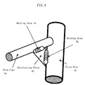
- Fig. 4 shows an example of weldment assembled by the automatic welding machine of Fig. 3.
- the sign 6a refers to a thin-walled pipe having a thickness of 0.8mm
- the sign 6b to a thick-walled pipe having a thickness of 1.6mm
- the sign 6c to a reinforcing plate.
- the thin-walled pipe 6a is welded to the reinforcing plate 6c (see the weld area 7a) in the "electrode negative" mode (the polarity setting signal Spn at the low level).
- the other pipe 6b is welded to the reinforcing plate 6c (see the weld area 7b) in the "electrode positive" mode (the polarity setting signal Spn at the high level).
- the necking current control is also performed to reduce spatters.
- the welding result is spatterless and suffers no burn through holes.
Landscapes
- Engineering & Computer Science (AREA)
- Physics & Mathematics (AREA)
- Plasma & Fusion (AREA)
- Mechanical Engineering (AREA)
- Arc Welding Control (AREA)
- Rectifiers (AREA)
- Generation Of Surge Voltage And Current (AREA)
Applications Claiming Priority (2)
| Application Number | Priority Date | Filing Date | Title |
|---|---|---|---|
| JP2002280132A JP4739641B2 (ja) | 2002-09-26 | 2002-09-26 | 短絡アーク溶接用電源装置及びロボット溶接装置 |
| JP2002280132 | 2002-09-26 |
Publications (3)
| Publication Number | Publication Date |
|---|---|
| EP1410867A2 true EP1410867A2 (de) | 2004-04-21 |
| EP1410867A3 EP1410867A3 (de) | 2004-11-24 |
| EP1410867B1 EP1410867B1 (de) | 2007-11-14 |
Family
ID=32025173
Family Applications (1)
| Application Number | Title | Priority Date | Filing Date |
|---|---|---|---|
| EP03255852A Expired - Lifetime EP1410867B1 (de) | 2002-09-26 | 2003-09-18 | Kurzschluss-Lichtbogenschweissversorgung und automatische Schweissvorrichtung dafür |
Country Status (5)
| Country | Link |
|---|---|
| US (1) | US6833529B2 (de) |
| EP (1) | EP1410867B1 (de) |
| JP (1) | JP4739641B2 (de) |
| CN (1) | CN1289249C (de) |
| DE (1) | DE60317441T2 (de) |
Cited By (1)
| Publication number | Priority date | Publication date | Assignee | Title |
|---|---|---|---|---|
| WO2007028858A1 (en) * | 2005-09-08 | 2007-03-15 | Kemppi Oy | Method and apparatus for short- arc welding |
Families Citing this family (34)
| Publication number | Priority date | Publication date | Assignee | Title |
|---|---|---|---|---|
| US9333580B2 (en) * | 2004-04-29 | 2016-05-10 | Lincoln Global, Inc. | Gas-less process and system for girth welding in high strength applications |
| JP4916759B2 (ja) * | 2006-04-20 | 2012-04-18 | 株式会社ダイヘン | 消耗電極交流パルスアーク溶接の極性切換制御方法 |
| US8067714B2 (en) | 2007-03-12 | 2011-11-29 | Daihen Corporation | Squeezing detection control method for consumable electrode arc welding |
| JP4965311B2 (ja) * | 2007-03-12 | 2012-07-04 | 株式会社ダイヘン | 消耗電極交流アーク溶接のくびれ検出制御方法 |
| JP5090759B2 (ja) * | 2007-03-12 | 2012-12-05 | 株式会社ダイヘン | 消耗電極交流アーク溶接電源の出力制御方法 |
| JP5090765B2 (ja) | 2007-03-29 | 2012-12-05 | 株式会社ダイヘン | 消耗電極交流アーク溶接の送給制御方法 |
| US9895760B2 (en) | 2007-09-26 | 2018-02-20 | Lincoln Global, Inc. | Method and system to increase heat input to a weld during a short-circuit arc welding process |
| SE532457C2 (sv) * | 2008-07-03 | 2010-01-26 | Esab Ab | Pulverhanteringsanordning för svetsning under pulver |
| JP2010214399A (ja) * | 2009-03-16 | 2010-09-30 | Daihen Corp | アーク溶接方法 |
| JP5083415B2 (ja) * | 2009-04-08 | 2012-11-28 | パナソニック株式会社 | アーク溶接方法およびアーク溶接装置 |
| JP5375389B2 (ja) * | 2009-07-15 | 2013-12-25 | パナソニック株式会社 | 溶接装置および溶接方法 |
| US20130334188A1 (en) * | 2010-12-21 | 2013-12-19 | Lincoln Global, Inc. | Power routing for welding suite |
| TWI442988B (zh) * | 2011-05-31 | 2014-07-01 | Metal Ind Res & Dev Ct | 自動銲接之方法 |
| JP5851798B2 (ja) * | 2011-10-28 | 2016-02-03 | 株式会社ダイヘン | 消耗電極アーク溶接のくびれ検出時電流制御方法 |
| JP5918061B2 (ja) * | 2012-07-30 | 2016-05-18 | 株式会社ダイヘン | 消耗電極アーク溶接制御方法 |
| US9656340B2 (en) | 2012-09-24 | 2017-05-23 | Lincoln Global, Inc. | Systems and methods providing low current regulation for AC arc welding processes |
| US9114471B2 (en) | 2012-09-24 | 2015-08-25 | Lincoln Global, Inc. | Systems and methods providing low current regulation for AC arc welding processes |
| US9120172B2 (en) * | 2012-09-24 | 2015-09-01 | Lincoln Global, Inc. | Systems and methods providing controlled AC arc welding processes |
| US9481046B2 (en) | 2012-09-24 | 2016-11-01 | Lincoln Global, Inc. | Systems and methods providing controlled AC arc welding processes |
| US10315268B2 (en) | 2012-11-07 | 2019-06-11 | Lincoln Global, Inc. | Method and system to control heat input in a welding operation |
| US9138823B2 (en) | 2012-11-13 | 2015-09-22 | Lincoln Global, Inc. | Systems and methods providing arc re-ignition for AC arc welding processes |
| KR102199238B1 (ko) * | 2014-02-24 | 2021-01-06 | 가부시키가이샤 다이헨 | 아크 용접 방법 |
| US10052706B2 (en) * | 2014-04-04 | 2018-08-21 | Lincoln Global, Inc. | Method and system to use AC welding waveform and enhanced consumable to improve welding of galvanized workpiece |
| US10369649B2 (en) | 2015-02-05 | 2019-08-06 | Lincoln Global, Inc. | Circuits for improved welding performance |
| JP6395644B2 (ja) * | 2015-02-27 | 2018-09-26 | 株式会社神戸製鋼所 | アーク溶接方法、アーク溶接装置およびアーク溶接用制御装置 |
| US10179369B2 (en) | 2015-10-27 | 2019-01-15 | Lincoln Global, Inc. | Welding system for AC welding with reduced spatter |
| JP6778857B2 (ja) * | 2016-03-29 | 2020-11-04 | パナソニックIpマネジメント株式会社 | アーク溶接制御方法 |
| US10682719B2 (en) | 2017-01-27 | 2020-06-16 | Lincoln Global, Inc. | Apparatus and method for welding with AC waveform |
| US11110536B2 (en) * | 2017-01-27 | 2021-09-07 | Lincoln Global, Inc. | Apparatus and method for welding with AC waveform |
| US10744584B2 (en) | 2017-01-27 | 2020-08-18 | Lincoln Global, Inc. | Apparatus and method for welding with AC waveform |
| US10722967B2 (en) | 2017-01-27 | 2020-07-28 | Lincoln Global, Inc. | Apparatus and method for welding with AC waveform |
| CN112653337A (zh) * | 2020-12-24 | 2021-04-13 | 唐山松下产业机器有限公司 | 交流斩波控制电路、控制方法、装置及介质 |
| EP4417983A4 (de) * | 2021-10-11 | 2025-09-10 | Hioki Electric Works | Messvorrichtung, messsystem und messverfahren |
| CN115341170B (zh) * | 2022-05-07 | 2026-04-03 | 浙江星辉电子有限公司 | 一种自动互为阴阳极电弧源清洗装置及镀膜机 |
Family Cites Families (12)
| Publication number | Priority date | Publication date | Assignee | Title |
|---|---|---|---|---|
| JPS59137177A (ja) * | 1983-01-27 | 1984-08-07 | Matsushita Electric Ind Co Ltd | 溶接用電源 |
| JPS59179274A (ja) * | 1983-03-30 | 1984-10-11 | Hitachi Ltd | ホットワイヤを用いた溶接装置 |
| US4546234A (en) * | 1983-08-11 | 1985-10-08 | Kabushiki Kaisha Kobe Seiko Sho | Output control of short circuit welding power source |
| US4553018A (en) * | 1983-10-27 | 1985-11-12 | Mitsubishi Denki Kabushiki Kaisha | Short circuiting transfer arc welding machine |
| JPS63157765A (ja) * | 1986-12-19 | 1988-06-30 | Kobe Steel Ltd | 短絡移行型ア−ク溶接機の出力制御方法および出力制御装置 |
| KR910004997B1 (ko) * | 1987-05-12 | 1991-07-20 | 가부시끼가이샤 고오베 세이꼬오쇼 | 소모전극식 아크용접용 전원시스템 |
| JP3305708B2 (ja) | 1990-04-20 | 2002-07-24 | 大日本印刷株式会社 | 電離放射線硬化表面の機能化方法 |
| JPH07116844A (ja) * | 1993-10-22 | 1995-05-09 | Matsushita Electric Ind Co Ltd | アーク溶接ロボットの制御装置 |
| JP3358080B2 (ja) * | 1997-09-20 | 2002-12-16 | 松下電器産業株式会社 | 極性切換制御方法および消耗電極式アーク溶接機 |
| US6051810A (en) * | 1998-01-09 | 2000-04-18 | Lincoln Global, Inc. | Short circuit welder |
| JP3809983B2 (ja) * | 1998-02-12 | 2006-08-16 | 日立ビアメカニクス株式会社 | 消耗電極式の交流ガスシールド溶接装置 |
| US6498321B1 (en) * | 2001-04-09 | 2002-12-24 | Lincoln Global, Inc. | System and method for controlling an electric arc welder |
-
2002
- 2002-09-26 JP JP2002280132A patent/JP4739641B2/ja not_active Expired - Fee Related
-
2003
- 2003-09-03 US US10/654,074 patent/US6833529B2/en not_active Expired - Lifetime
- 2003-09-18 DE DE60317441T patent/DE60317441T2/de not_active Expired - Lifetime
- 2003-09-18 EP EP03255852A patent/EP1410867B1/de not_active Expired - Lifetime
- 2003-09-24 CN CN03134805.XA patent/CN1289249C/zh not_active Expired - Fee Related
Cited By (4)
| Publication number | Priority date | Publication date | Assignee | Title |
|---|---|---|---|---|
| WO2007028858A1 (en) * | 2005-09-08 | 2007-03-15 | Kemppi Oy | Method and apparatus for short- arc welding |
| EP1940578A4 (de) * | 2005-09-08 | 2010-12-29 | Kemppi Oy | Verfahren und vorrichtung zum schweissen mit kurzem lichtbogen |
| AU2006289052B2 (en) * | 2005-09-08 | 2011-06-09 | Kemppi Oy | Method and apparatus for short - arc welding |
| CN101262976B (zh) * | 2005-09-08 | 2011-07-13 | 肯倍公司 | 用于短弧焊的方法和设备 |
Also Published As
| Publication number | Publication date |
|---|---|
| EP1410867A3 (de) | 2004-11-24 |
| DE60317441T2 (de) | 2008-03-06 |
| US6833529B2 (en) | 2004-12-21 |
| DE60317441D1 (de) | 2007-12-27 |
| CN1496775A (zh) | 2004-05-19 |
| JP4739641B2 (ja) | 2011-08-03 |
| CN1289249C (zh) | 2006-12-13 |
| EP1410867B1 (de) | 2007-11-14 |
| JP2004114088A (ja) | 2004-04-15 |
| US20040060913A1 (en) | 2004-04-01 |
Similar Documents
| Publication | Publication Date | Title |
|---|---|---|
| EP1410867B1 (de) | Kurzschluss-Lichtbogenschweissversorgung und automatische Schweissvorrichtung dafür | |
| US7495193B2 (en) | Pipe seam tack welding methods and apparatus using modified series arc welding | |
| EP0607819B1 (de) | Vorrichtung zum Schweissen mit pulsierendem Lichtbogen und abschmelzendem Elektrodendraht | |
| JP4965311B2 (ja) | 消耗電極交流アーク溶接のくびれ検出制御方法 | |
| JP3809983B2 (ja) | 消耗電極式の交流ガスシールド溶接装置 | |
| JP4916759B2 (ja) | 消耗電極交流パルスアーク溶接の極性切換制御方法 | |
| JP2006247710A (ja) | 消耗電極アーク溶接のくびれ検出時電流制御方法 | |
| US6037554A (en) | Consumable electrode type pulsed arc welder and controlling method for the same | |
| US20220055136A1 (en) | Arc welding method and arc welding device | |
| JPH07116839A (ja) | 消耗電極式直流アーク溶接機 | |
| US5942139A (en) | Consumable electrode DC arc welder | |
| JP5349152B2 (ja) | 交流パルスアーク溶接制御方法 | |
| JP4211724B2 (ja) | アーク溶接制御方法及びアーク溶接装置 | |
| JP3110295B2 (ja) | 消耗電極式交流アーク溶接機の制御方法 | |
| JP3813732B2 (ja) | パルスアーク溶接の制御方法及び装置 | |
| CN115461178B (zh) | 直流电弧焊接控制方法 | |
| JPS6255472B2 (de) | ||
| JP4676094B2 (ja) | 溶接電源装置の出力電圧制御方法 | |
| JP2515273B2 (ja) | 短絡移行ア−ク溶接方法及びその装置 | |
| JP2022185997A (ja) | パルスアーク溶接電源 | |
| JP2022185998A (ja) | アーク溶接電源 | |
| JP4643236B2 (ja) | 極性切換短絡アーク溶接方法 | |
| JP4875443B2 (ja) | 消耗電極アーク溶接電源の出力制御方法 | |
| JP2025068841A (ja) | 非消耗電極アーク溶接の溶接開始方法 | |
| JPH1177304A (ja) | 消耗電極式アーク溶接機の出力制御装置 |
Legal Events
| Date | Code | Title | Description |
|---|---|---|---|
| PUAI | Public reference made under article 153(3) epc to a published international application that has entered the european phase |
Free format text: ORIGINAL CODE: 0009012 |
|
| AK | Designated contracting states |
Kind code of ref document: A2 Designated state(s): AT BE BG CH CY CZ DE DK EE ES FI FR GB GR HU IE IT LI LU MC NL PT RO SE SI SK TR |
|
| AX | Request for extension of the european patent |
Extension state: AL LT LV MK |
|
| PUAL | Search report despatched |
Free format text: ORIGINAL CODE: 0009013 |
|
| AK | Designated contracting states |
Kind code of ref document: A3 Designated state(s): AT BE BG CH CY CZ DE DK EE ES FI FR GB GR HU IE IT LI LU MC NL PT RO SE SI SK TR |
|
| AX | Request for extension of the european patent |
Extension state: AL LT LV MK |
|
| RIC1 | Information provided on ipc code assigned before grant |
Ipc: 7B 23K 9/10 A Ipc: 7B 23K 9/09 B |
|
| AKX | Designation fees paid | ||
| REG | Reference to a national code |
Ref country code: DE Ref legal event code: 8566 |
|
| RBV | Designated contracting states (corrected) |
Designated state(s): DE GB |
|
| 17P | Request for examination filed |
Effective date: 20050802 |
|
| RBV | Designated contracting states (corrected) |
Designated state(s): DE GB |
|
| GRAP | Despatch of communication of intention to grant a patent |
Free format text: ORIGINAL CODE: EPIDOSNIGR1 |
|
| GRAS | Grant fee paid |
Free format text: ORIGINAL CODE: EPIDOSNIGR3 |
|
| GRAA | (expected) grant |
Free format text: ORIGINAL CODE: 0009210 |
|
| AK | Designated contracting states |
Kind code of ref document: B1 Designated state(s): DE GB |
|
| REG | Reference to a national code |
Ref country code: GB Ref legal event code: FG4D |
|
| REF | Corresponds to: |
Ref document number: 60317441 Country of ref document: DE Date of ref document: 20071227 Kind code of ref document: P |
|
| PLBE | No opposition filed within time limit |
Free format text: ORIGINAL CODE: 0009261 |
|
| STAA | Information on the status of an ep patent application or granted ep patent |
Free format text: STATUS: NO OPPOSITION FILED WITHIN TIME LIMIT |
|
| 26N | No opposition filed |
Effective date: 20080815 |
|
| PGFP | Annual fee paid to national office [announced via postgrant information from national office to epo] |
Ref country code: DE Payment date: 20200909 Year of fee payment: 18 Ref country code: GB Payment date: 20200909 Year of fee payment: 18 |
|
| REG | Reference to a national code |
Ref country code: DE Ref legal event code: R119 Ref document number: 60317441 Country of ref document: DE |
|
| GBPC | Gb: european patent ceased through non-payment of renewal fee |
Effective date: 20210918 |
|
| PG25 | Lapsed in a contracting state [announced via postgrant information from national office to epo] |
Ref country code: GB Free format text: LAPSE BECAUSE OF NON-PAYMENT OF DUE FEES Effective date: 20210918 Ref country code: DE Free format text: LAPSE BECAUSE OF NON-PAYMENT OF DUE FEES Effective date: 20220401 |