EP1409316B1 - Vorrichtung und verfahren zur erfassung von bremsdrücken - Google Patents
Vorrichtung und verfahren zur erfassung von bremsdrücken Download PDFInfo
- Publication number
- EP1409316B1 EP1409316B1 EP02747326.3A EP02747326A EP1409316B1 EP 1409316 B1 EP1409316 B1 EP 1409316B1 EP 02747326 A EP02747326 A EP 02747326A EP 1409316 B1 EP1409316 B1 EP 1409316B1
- Authority
- EP
- European Patent Office
- Prior art keywords
- pressure
- valve block
- regulating device
- correction
- transducer
- Prior art date
- Legal status (The legal status is an assumption and is not a legal conclusion. Google has not performed a legal analysis and makes no representation as to the accuracy of the status listed.)
- Expired - Lifetime
Links
- 238000000034 method Methods 0.000 title claims description 11
- 238000012937 correction Methods 0.000 claims description 22
- 230000003750 conditioning effect Effects 0.000 claims description 9
- 230000001105 regulatory effect Effects 0.000 claims description 8
- 238000009530 blood pressure measurement Methods 0.000 claims description 4
- 239000012530 fluid Substances 0.000 claims description 4
- 238000004364 calculation method Methods 0.000 claims description 3
- 238000011156 evaluation Methods 0.000 claims description 3
- 238000004519 manufacturing process Methods 0.000 claims description 3
- 230000003321 amplification Effects 0.000 claims description 2
- 238000003199 nucleic acid amplification method Methods 0.000 claims description 2
- 239000011159 matrix material Substances 0.000 claims 2
- 238000012545 processing Methods 0.000 description 5
- 238000005259 measurement Methods 0.000 description 4
- 230000001953 sensory effect Effects 0.000 description 4
- 230000001419 dependent effect Effects 0.000 description 3
- 230000013011 mating Effects 0.000 description 3
- 230000007613 environmental effect Effects 0.000 description 2
- 239000012528 membrane Substances 0.000 description 2
- 101100382340 Arabidopsis thaliana CAM2 gene Proteins 0.000 description 1
- 101100494530 Brassica oleracea var. botrytis CAL-A gene Proteins 0.000 description 1
- 101100165913 Brassica oleracea var. italica CAL gene Proteins 0.000 description 1
- 101150118283 CAL1 gene Proteins 0.000 description 1
- 102100021849 Calretinin Human genes 0.000 description 1
- 101000898072 Homo sapiens Calretinin Proteins 0.000 description 1
- 101100029577 Saccharomyces cerevisiae (strain ATCC 204508 / S288c) CDC43 gene Proteins 0.000 description 1
- 101100439683 Saccharomyces cerevisiae (strain ATCC 204508 / S288c) CHS3 gene Proteins 0.000 description 1
- 230000005540 biological transmission Effects 0.000 description 1
- 101150014174 calm gene Proteins 0.000 description 1
- 238000006243 chemical reaction Methods 0.000 description 1
- 239000002131 composite material Substances 0.000 description 1
- 238000010276 construction Methods 0.000 description 1
- 230000001276 controlling effect Effects 0.000 description 1
- 238000013500 data storage Methods 0.000 description 1
- 238000013461 design Methods 0.000 description 1
- 230000005284 excitation Effects 0.000 description 1
- 238000009434 installation Methods 0.000 description 1
- 230000010354 integration Effects 0.000 description 1
- 238000007789 sealing Methods 0.000 description 1
- 238000000926 separation method Methods 0.000 description 1
- 239000010409 thin film Substances 0.000 description 1
Images


Classifications
-
- B—PERFORMING OPERATIONS; TRANSPORTING
- B60—VEHICLES IN GENERAL
- B60T—VEHICLE BRAKE CONTROL SYSTEMS OR PARTS THEREOF; BRAKE CONTROL SYSTEMS OR PARTS THEREOF, IN GENERAL; ARRANGEMENT OF BRAKING ELEMENTS ON VEHICLES IN GENERAL; PORTABLE DEVICES FOR PREVENTING UNWANTED MOVEMENT OF VEHICLES; VEHICLE MODIFICATIONS TO FACILITATE COOLING OF BRAKES
- B60T8/00—Arrangements for adjusting wheel-braking force to meet varying vehicular or ground-surface conditions, e.g. limiting or varying distribution of braking force
- B60T8/32—Arrangements for adjusting wheel-braking force to meet varying vehicular or ground-surface conditions, e.g. limiting or varying distribution of braking force responsive to a speed condition, e.g. acceleration or deceleration
- B60T8/34—Arrangements for adjusting wheel-braking force to meet varying vehicular or ground-surface conditions, e.g. limiting or varying distribution of braking force responsive to a speed condition, e.g. acceleration or deceleration having a fluid pressure regulator responsive to a speed condition
- B60T8/36—Arrangements for adjusting wheel-braking force to meet varying vehicular or ground-surface conditions, e.g. limiting or varying distribution of braking force responsive to a speed condition, e.g. acceleration or deceleration having a fluid pressure regulator responsive to a speed condition including a pilot valve responding to an electromagnetic force
- B60T8/3615—Electromagnetic valves specially adapted for anti-lock brake and traction control systems
- B60T8/3675—Electromagnetic valves specially adapted for anti-lock brake and traction control systems integrated in modulator units
-
- B—PERFORMING OPERATIONS; TRANSPORTING
- B60—VEHICLES IN GENERAL
- B60T—VEHICLE BRAKE CONTROL SYSTEMS OR PARTS THEREOF; BRAKE CONTROL SYSTEMS OR PARTS THEREOF, IN GENERAL; ARRANGEMENT OF BRAKING ELEMENTS ON VEHICLES IN GENERAL; PORTABLE DEVICES FOR PREVENTING UNWANTED MOVEMENT OF VEHICLES; VEHICLE MODIFICATIONS TO FACILITATE COOLING OF BRAKES
- B60T13/00—Transmitting braking action from initiating means to ultimate brake actuator with power assistance or drive; Brake systems incorporating such transmitting means, e.g. air-pressure brake systems
- B60T13/10—Transmitting braking action from initiating means to ultimate brake actuator with power assistance or drive; Brake systems incorporating such transmitting means, e.g. air-pressure brake systems with fluid assistance, drive, or release
- B60T13/66—Electrical control in fluid-pressure brake systems
- B60T13/662—Electrical control in fluid-pressure brake systems characterised by specified functions of the control system components
-
- B—PERFORMING OPERATIONS; TRANSPORTING
- B60—VEHICLES IN GENERAL
- B60T—VEHICLE BRAKE CONTROL SYSTEMS OR PARTS THEREOF; BRAKE CONTROL SYSTEMS OR PARTS THEREOF, IN GENERAL; ARRANGEMENT OF BRAKING ELEMENTS ON VEHICLES IN GENERAL; PORTABLE DEVICES FOR PREVENTING UNWANTED MOVEMENT OF VEHICLES; VEHICLE MODIFICATIONS TO FACILITATE COOLING OF BRAKES
- B60T13/00—Transmitting braking action from initiating means to ultimate brake actuator with power assistance or drive; Brake systems incorporating such transmitting means, e.g. air-pressure brake systems
- B60T13/10—Transmitting braking action from initiating means to ultimate brake actuator with power assistance or drive; Brake systems incorporating such transmitting means, e.g. air-pressure brake systems with fluid assistance, drive, or release
- B60T13/66—Electrical control in fluid-pressure brake systems
- B60T13/68—Electrical control in fluid-pressure brake systems by electrically-controlled valves
-
- B—PERFORMING OPERATIONS; TRANSPORTING
- B60—VEHICLES IN GENERAL
- B60T—VEHICLE BRAKE CONTROL SYSTEMS OR PARTS THEREOF; BRAKE CONTROL SYSTEMS OR PARTS THEREOF, IN GENERAL; ARRANGEMENT OF BRAKING ELEMENTS ON VEHICLES IN GENERAL; PORTABLE DEVICES FOR PREVENTING UNWANTED MOVEMENT OF VEHICLES; VEHICLE MODIFICATIONS TO FACILITATE COOLING OF BRAKES
- B60T17/00—Component parts, details, or accessories of power brake systems not covered by groups B60T8/00, B60T13/00 or B60T15/00, or presenting other characteristic features
- B60T17/18—Safety devices; Monitoring
-
- B—PERFORMING OPERATIONS; TRANSPORTING
- B60—VEHICLES IN GENERAL
- B60T—VEHICLE BRAKE CONTROL SYSTEMS OR PARTS THEREOF; BRAKE CONTROL SYSTEMS OR PARTS THEREOF, IN GENERAL; ARRANGEMENT OF BRAKING ELEMENTS ON VEHICLES IN GENERAL; PORTABLE DEVICES FOR PREVENTING UNWANTED MOVEMENT OF VEHICLES; VEHICLE MODIFICATIONS TO FACILITATE COOLING OF BRAKES
- B60T2250/00—Monitoring, detecting, estimating vehicle conditions
- B60T2250/06—Sensor zero-point adjustment; Offset compensation
-
- B—PERFORMING OPERATIONS; TRANSPORTING
- B60—VEHICLES IN GENERAL
- B60T—VEHICLE BRAKE CONTROL SYSTEMS OR PARTS THEREOF; BRAKE CONTROL SYSTEMS OR PARTS THEREOF, IN GENERAL; ARRANGEMENT OF BRAKING ELEMENTS ON VEHICLES IN GENERAL; PORTABLE DEVICES FOR PREVENTING UNWANTED MOVEMENT OF VEHICLES; VEHICLE MODIFICATIONS TO FACILITATE COOLING OF BRAKES
- B60T2270/00—Further aspects of brake control systems not otherwise provided for
- B60T2270/88—Pressure measurement in brake systems
Definitions
- the invention relates to a method for error compensation according to the preamble of claim 1 and an electro-hydraulic pressure control device according to the preamble of claim 5, in particular in electro-hydraulic control devices for electronically controlled brakes (ABS, ASR, ESP, etc.) for motor vehicles.
- ABS electronically controlled brakes
- ASR electronically controlled brakes
- ESP ESP
- Electronically regulating braking devices are known ( Brake Manual, "Electronic Brake Systems", 1955, ISBN 3-89059-026-8 ). They consist of the combination of a hydraulic control unit, which is also referred to as a valve block, and an electronic controller (ER).
- the hydraulic control unit comprises a motor-pump unit and a valve block flanged thereto.
- the engine-pump unit provides the pressurized fluid volume needed in the pressurization phase.
- the combined in the hydraulic control unit intake and exhaust valves allow the modulation of the wheel brake pressures.
- the brake lines to the wheel brakes are connected to the valve block.
- the hydraulic valves in the valve block are actuated by electromagnetic coils, which are arranged within the electronic controller housing.
- the electronic controller is supplied, inter alia, the signals of four wheel speed sensors.
- a valve block with arranged thereon pressure sensor cluster and with a hydraulic pump for a motor vehicle brake system is known.
- the pressure sensors are via tube connections in contact with the respectively prevailing in the wheel brakes and the master cylinder pressure.
- a circuit for processing the pressure sensor signals is part of the pressure sensor cluster.
- the valve block connected to the pressure sensor cluster to a common module is electrically connected to an electronic control unit.
- the electronic control unit monitors the pressure signals of the pressure sensor cluster and, depending on these, activates the hydraulic pump and the valves in the valve block.
- the invention provides to develop a known electro-hydraulic pressure control device according to claim 5.
- pressure transducers are preferably formed in the manner that a passive uncompensated strain gauge is applied to the pressure measuring diaphragm, which is connected in particular with a corresponding number of contact surfaces for establishing an electrical connection to the electronic controller via mating contacts.
- the connection via mating contacts is carried out according to the invention preferably waiving the customary in the prior art integration of an active electronic circuit for signal pre-amplification, signal processing and error compensation the measuring bridge.
- the invention also relates to brake devices which additionally evaluate the pressure information of one or more hydraulic connections in the valve block.
- the invention proposes to realize the electronic signal processing for all individual pressure transducers of existing in the hydraulic control unit pressure channels circuitry as part of an integrated circuit in the electronic controller. It is particularly useful to provide exactly one integrated circuit. However, a simplification is already achieved when the number of integrated circuits is chosen numerically lower than the number of existing pressure transducers.
- the electronic controller has computation means, in particular realized by one or more microcomputers or controllers, with which the errors of the measuring chain of each individual pressure channel can be eliminated by electronic evaluation of two functionally separate correction quantity computations or correction tables at least substantially.
- the attachment of the housing body of the pressure transducer to the hydraulic control unit either via a mounting frame (eg a perforated plate), using suitable fasteners (eg one or more screws) or also preferably in such a way that the housing body of the pressure transducer directly to the hydraulic Control unit, in particular by means of clinch connections, are attached.
- a mounting frame eg a perforated plate
- suitable fasteners eg one or more screws
- the invention further relates to a method for error compensation according to claim 1.
- a pressure transducer converts the pressure (differential pressure) detected at a measuring diaphragm to an electrical signal (eg ohmic resistance of the measuring bridge).
- an individual sensor is first calibrated or calibrated.
- the value pairs, which assign the electrical parameter to the physical pressure variable are generally dependent on further environmental parameters, in particular the ambient temperature. It makes sense first to define by definition a suitable association between the pressure variable and the electrical quantity and to refer to existing deviations of the electrical signal value from the expected signal value as a setpoint deviation.
- the setpoint deviations of an individual pressure transducer as a function of pressure and temperature and / or the setpoint deviations of the signal conditioning stage associated with the individual pressure transducer, in particular including the associated analog to digital converter are determined as a function of the signal input voltage and / or the temperature via interpolation point measurements and kept individually stored in the electronic controller stored in data storage.
- Signal conditioning channel (s) (mainly “electronic” components of the pressure sensor channel (s)).
- a spatial separation of the above correction value determination is particularly useful when the production of the mechanical and electronic components of the device according to the invention takes place at different locations.
- a measured value determined at the pressure sensor is converted into a corrected pressure value using two mutually linked correction values.
- This conversion is conveniently done individually for each hydraulic channel, e.g. by applying two or more correction value matrices.
- the device and the method of the present invention can be used particularly advantageously in electrohydraulic brake systems (EHB).
- EHB electrohydraulic brake systems
- the solution according to the invention offers, inter alia, in arrangements with several pressure transducers the advantage of a considerable simplification and cost reduction.
- the reason for this is essentially the simplification in the electronic evaluation circuit of the pressure sensors, which manages with a smaller number of electronic components.
- Another advantage is that can be used on already proven in mass production mechanical / hydraulic structures.
- the calibration effort is advantageously reduced to a measurement of the error curve before or in particular after installation of the component in the motor vehicle.
- the motor vehicle manufacturer can advantageously the integrated circuit and the Pressure transducer on the tape together to form a structural unit. It is also possible to perform a calibration after the completion of a control unit of hydraulic unit and electronic controller at the manufacturer of the brake system.
- a significant advantage is that no calibration needs to be made at the manufacturer of the pressure sensors.
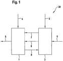
- Fig. 1 schematically shows the essential functional blocks of a known electro-hydraulic pressure control device 30 (control unit) for controlling hydraulically actuated motor vehicle brakes.
- Pressure control device 30 consists of a valve block 1 and an electronic controller 2.
- Valve block and electronic controller form a structural unit. Valve block and electronic controller are connected via an electrical and magnetic interface 7,8,9.
- the electronic controller electrical energy 3, the valve block hydraulic energy 4 is supplied.
- Controller 2 are also supplied with additional sensor signals 5 from external sensors, such as wheel speed sensors, yaw rate sensors, switch states, etc., with which the current driving condition can be determined.
- Valve block 1 passes in response to the signals of the electronic control pressure modulated brake fluid 6 to the brakes.
- the composite interfaces 7, 8, 9 result.
- 7 is an electrical connector for powering the pump motor and 9 a sensory interface to Transmission of pressure signals.
- 8 is a so-called “magnetic plug", with which a control of the hydraulic valves in the valve block takes place magnetically via coils.
- Fig. 2 shows the construction scheme of the brake system or the brake control device 30.
- Electronic controller 2 is surrounded by a substantially cup-shaped housing which receives on a side facing the valve block, the valve coils 12 for engagement in valve dome 11. In combination with the valve block, this results in cavity 10 in which the elements of the interfaces 7, 8, 9 are made Fig. 1 are housed protected by environmental influences.
- an armature is magnetically moved in valve dome 11, so that the arranged in the valve block, connected to the valve dome hydraulic valve is actuated.
- the version 14 connected to regulator 2 and the pressure sensor 15 connected to valve block 1 forms the sensory interface 9.
- valve domes are inserted into corresponding bores in the coils.
- an electrical connection of the sensor interface 9 and the unsigned electrical connection 7 for the pump motor is Embedded in the housing of the electronic controller.
- an electronic circuit carrier 13 to which the electrically converted pressure signals are supplied and which, inter alia, generates electrical signals for coil excitation.
- Fig. 3a is shown by means of function blocks, the structure of the pressure sensor arrangement according to the invention using the example of a single sensor.
- Pressure transducer 16 has a Druckmeßmembran 32 and mounted thereon, passive and uncompensated strain gauge 33. Furthermore, the pressure transducer has a corresponding number of contact surfaces 31 for producing an electrical connection 17 with the electronic controller via mating contacts 32 on. In pressure transducer 16 no electrically active components (eg amplifiers) are included.
- the measuring bridges B are known piezoresistive resistors or stretchable thin film resistors, which are connected to the membrane.
- Partial image b of Fig. 3 shows an example of a pressure sensor arrangement according to the invention with a plurality of pressure sensors, in which the electronic signal processing stage 27 is implemented for all individual pressure transducers of the pressure channels p1, p2, p3, ..., etc. circuitry as part of an integrated circuit 29 in the electronic controller, which summarizes the active components of the individual sensors on a common chip.
- a calibration of the electrical signals of the sensor 16 is performed in the measurement in electronic controller 2.
- Each individual electrical pressure signal is converted via analog / digital converter 28 into a digital signal.
- a signal conditioning stage 27 may be provided, which together with the A / D converter comprises a signal conditioning channel.
- the electronic calibration is carried out program-controlled in a microprocessor system 37.
- Microprocessor system 37 carries out a method by which the determined measured values are corrected by means of two functionally separate stored correction quantity calculations 35, 36 or correction tables.
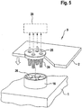
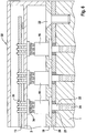
- the sensory interface is in the FIGS. 4 and 5 shown.
- Wheatstone bridge 33 which is composed of resistive strain gauges for pressure determination.
- a temperature determination can also be made either by measuring the temperature-dependent resistance of bridge 33 or by means of an additional temperature sensor.
- the connections of bridge 33 lead via metallic or metallized contact surfaces 26, which are connected to the housing body of the pressure transducer 16, to integrated circuit 29.
- Druckmeßwandler 16 is inserted into the valve block 1.
- contact springs 24 are attached. When valve block 1 and the housing of the electronic controller 2 are guided towards each other, an electrical connection is established by placing contact springs 24 on contact surfaces 26 (interface 9).
- Fig. 6 shows an example of the attachment of the housing body of the pressure transducer 16 via a plate 19 with screws 22 to valve block 1. Between plate 19 and valve block 1, a sealing plate 20 is inserted with recessed seals 21. At pressure transducer 16 risers 23 are attached, which are acted upon by individual hydraulic channels 34 with hydraulic fluid. With housing 2 of the electronic controller contact springs 24 are connected. Of springs 24 exist electrical connections, which in corresponding holes of the circuit board circuit board 13 protrude and soldered to this or are connected by known per se pressure contacts conductive.
Landscapes
- Engineering & Computer Science (AREA)
- Transportation (AREA)
- Mechanical Engineering (AREA)
- Physics & Mathematics (AREA)
- Electromagnetism (AREA)
- Fluid Mechanics (AREA)
- Regulating Braking Force (AREA)
Applications Claiming Priority (5)
| Application Number | Priority Date | Filing Date | Title |
|---|---|---|---|
| DE10133293 | 2001-07-12 | ||
| DE10133293 | 2001-07-12 | ||
| DE10205012A DE10205012A1 (de) | 2001-07-12 | 2002-02-07 | Vorrichtung und Verfahren zur Erfassung von Bremsdrücken |
| DE10205012 | 2002-02-07 | ||
| PCT/EP2002/005838 WO2003006294A1 (de) | 2001-07-12 | 2002-05-28 | Vorrichtung und verfahren zur erfassung von bremsdrücken |
Publications (2)
| Publication Number | Publication Date |
|---|---|
| EP1409316A1 EP1409316A1 (de) | 2004-04-21 |
| EP1409316B1 true EP1409316B1 (de) | 2017-03-08 |
Family
ID=26009668
Family Applications (1)
| Application Number | Title | Priority Date | Filing Date |
|---|---|---|---|
| EP02747326.3A Expired - Lifetime EP1409316B1 (de) | 2001-07-12 | 2002-05-28 | Vorrichtung und verfahren zur erfassung von bremsdrücken |
Country Status (4)
| Country | Link |
|---|---|
| US (1) | US20040178674A1 (enExample) |
| EP (1) | EP1409316B1 (enExample) |
| JP (1) | JP2004533968A (enExample) |
| WO (1) | WO2003006294A1 (enExample) |
Families Citing this family (5)
| Publication number | Priority date | Publication date | Assignee | Title |
|---|---|---|---|---|
| JP2006513905A (ja) * | 2003-02-20 | 2006-04-27 | コンチネンタル・テベス・アーゲー・ウント・コンパニー・オーハーゲー | 圧力コントローラ |
| DE102005042888A1 (de) * | 2005-05-13 | 2006-11-16 | Continental Teves Ag & Co. Ohg | Drucksteuerventil |
| KR102703548B1 (ko) * | 2019-12-26 | 2024-09-05 | 현대모비스 주식회사 | 차량 제동 시스템의 압력 제어 장치 및 방법 |
| CN113635877B (zh) * | 2021-08-20 | 2022-09-30 | 中汽创智科技有限公司 | 一种电液控制单元 |
| US12018765B2 (en) * | 2022-05-06 | 2024-06-25 | Sartorius Stedim Chromatography Systems Ltd. | Valve setup for SMB chromatography |
Family Cites Families (14)
| Publication number | Priority date | Publication date | Assignee | Title |
|---|---|---|---|---|
| US4108008A (en) * | 1977-10-26 | 1978-08-22 | United Technologies Corporation | Quick connect multiple fluid/electrical transducer apparatus |
| US4442716A (en) * | 1982-04-30 | 1984-04-17 | The United States Of America As Represented By The Administrator Of The National Areonautics And Space Administration | Electronic scanning pressure measuring system and transducer package |
| US4753105A (en) * | 1987-01-22 | 1988-06-28 | Pressure Systems Incorporated | Electronic pressure scanner |
| DE19521832A1 (de) * | 1995-06-16 | 1996-12-19 | Bosch Gmbh Robert | Druckmeßvorrichtung |
| DE19711366A1 (de) | 1997-03-19 | 1998-09-24 | Bosch Gmbh Robert | Meßvorrichtung |
| DE19755821A1 (de) | 1997-12-16 | 1999-06-17 | Bosch Gmbh Robert | Bremsanlage für Fahrzeuge |
| US6220101B1 (en) * | 1998-02-03 | 2001-04-24 | Ssi Technologies, Inc. | Apparatus for measuring multiple pressures |
| DE19841334A1 (de) * | 1998-03-31 | 1999-10-07 | Itt Mfg Enterprises Inc | Drucksensorbaugruppe |
| WO1999050115A1 (de) * | 1998-03-31 | 1999-10-07 | Continental Teves Ag & Co. Ohg | Drucksensorbaugruppe |
| GB9820621D0 (en) | 1998-09-23 | 1998-11-18 | Lucas Ind Plc | Improvements relating to electro-hydraulic braking systems |
| EP1133423A1 (en) | 1998-11-25 | 2001-09-19 | Kelsey-Hayes Company | Structure for mounting a cluster of pressure sensors upon an electro-hydraulic brake system control unit |
| DE19917941A1 (de) * | 1999-04-21 | 2000-10-26 | Bosch Gmbh Robert | Bremsgerät für Fahrzeugbremssysteme |
| EP1282544B1 (de) | 2000-05-11 | 2006-07-19 | Continental Teves AG & Co. oHG | Bremsvorrichtung mit integriertem drucksensormodul |
| US6434456B1 (en) * | 2000-09-07 | 2002-08-13 | Kelsey-Hayes Company | High reliability pressure sensor |
-
2002
- 2002-05-28 WO PCT/EP2002/005838 patent/WO2003006294A1/de not_active Ceased
- 2002-05-28 JP JP2003512080A patent/JP2004533968A/ja active Pending
- 2002-05-28 US US10/483,351 patent/US20040178674A1/en not_active Abandoned
- 2002-05-28 EP EP02747326.3A patent/EP1409316B1/de not_active Expired - Lifetime
Non-Patent Citations (1)
| Title |
|---|
| None * |
Also Published As
| Publication number | Publication date |
|---|---|
| EP1409316A1 (de) | 2004-04-21 |
| WO2003006294A1 (de) | 2003-01-23 |
| JP2004533968A (ja) | 2004-11-11 |
| US20040178674A1 (en) | 2004-09-16 |
Similar Documents
| Publication | Publication Date | Title |
|---|---|---|
| EP0824429B1 (de) | Hydraulische kraftfahrzeugbremsanlage mit bremsschlupfregelung und/oder automatischem bremseneingriff zur antriebs- und/oder fahrdynamikregelung | |
| EP1282544B1 (de) | Bremsvorrichtung mit integriertem drucksensormodul | |
| EP2956339B1 (de) | Bremsvorrichtung mit einem wegsensor für integrierte kraftfahrzeugbremssysteme | |
| EP2398684B1 (de) | Elektro-pneumatisches druckregelmodul mit pneumatisch kreisgetrennten druckregelkanälen | |
| EP0651705B1 (de) | Verfahren zur erhöhung der funktionssicherheit einer bremsanlage mit elektronischer regelung der bremskraftverteilung | |
| EP3684659A1 (de) | Bremsanlage für ein kraftfahrzeug sowie verfahren zu deren betrieb | |
| DE3501179A1 (de) | Elektrische bremsanlage | |
| EP1337422B1 (de) | Vorrichtung zur ermittlung von positionen und bewegungen eines bremspedales für eine fahrzeugbremsanlage | |
| DE4227083C2 (de) | Elektronisches Bremssystem, insbesondere für Straßenfahrzeuge | |
| DE4228893A1 (de) | System zur Beeinflussung der Fahrdynamik eines Kraftfahrzeugs | |
| EP0949130B1 (de) | Steuereinrichtung für eine Fahrzeug-Bremsanlage | |
| EP1409316B1 (de) | Vorrichtung und verfahren zur erfassung von bremsdrücken | |
| EP0481027B1 (de) | Verfahren zur uberwachung des bremsentlüftungszustands | |
| EP1012555B1 (de) | Drucksensor | |
| DE10205012A1 (de) | Vorrichtung und Verfahren zur Erfassung von Bremsdrücken | |
| EP3867112B1 (de) | Aktuatormodul und verfahren zur messung und verarbeitung einer fahrdynamischen grösse eines fahrzeugs | |
| EP1419075A1 (de) | Elektrohydraulische druckregelvorrichtung | |
| DE10011796B4 (de) | Verfahren und Anordnung zum Bestimmen der Kenngrößsen | |
| DE10329489B4 (de) | Drucksteuergerät | |
| DE102007018515A1 (de) | Vorrichtung zur Bremsdruckregelung mit Blockierschutzfunktion und weiteren Regelungen | |
| DE102020201084A1 (de) | Drucksensoreinheit | |
| DE10302280A1 (de) | Drucksensormodul | |
| EP1544072A1 (de) | Elektronisch geregeltes Bremssystem | |
| JP2004533968A5 (enExample) | ||
| DE10255510A1 (de) | Vorrichtung und Verfahren zum Testen eines elektronischen Steuergeräts |
Legal Events
| Date | Code | Title | Description |
|---|---|---|---|
| PUAI | Public reference made under article 153(3) epc to a published international application that has entered the european phase |
Free format text: ORIGINAL CODE: 0009012 |
|
| 17P | Request for examination filed |
Effective date: 20040212 |
|
| AK | Designated contracting states |
Kind code of ref document: A1 Designated state(s): AT BE CH CY DE DK ES FI FR GB GR IE IT LI LU MC NL PT SE TR |
|
| 17Q | First examination report despatched |
Effective date: 20090420 |
|
| GRAP | Despatch of communication of intention to grant a patent |
Free format text: ORIGINAL CODE: EPIDOSNIGR1 |
|
| INTG | Intention to grant announced |
Effective date: 20161028 |
|
| GRAS | Grant fee paid |
Free format text: ORIGINAL CODE: EPIDOSNIGR3 |
|
| GRAA | (expected) grant |
Free format text: ORIGINAL CODE: 0009210 |
|
| AK | Designated contracting states |
Kind code of ref document: B1 Designated state(s): DE FR GB IT |
|
| REG | Reference to a national code |
Ref country code: GB Ref legal event code: FG4D Free format text: NOT ENGLISH |
|
| REG | Reference to a national code |
Ref country code: DE Ref legal event code: R096 Ref document number: 50216220 Country of ref document: DE |
|
| PG25 | Lapsed in a contracting state [announced via postgrant information from national office to epo] |
Ref country code: IT Free format text: LAPSE BECAUSE OF FAILURE TO SUBMIT A TRANSLATION OF THE DESCRIPTION OR TO PAY THE FEE WITHIN THE PRESCRIBED TIME-LIMIT Effective date: 20170308 |
|
| REG | Reference to a national code |
Ref country code: DE Ref legal event code: R097 Ref document number: 50216220 Country of ref document: DE |
|
| PLBE | No opposition filed within time limit |
Free format text: ORIGINAL CODE: 0009261 |
|
| STAA | Information on the status of an ep patent application or granted ep patent |
Free format text: STATUS: NO OPPOSITION FILED WITHIN TIME LIMIT |
|
| 26N | No opposition filed |
Effective date: 20171211 |
|
| GBPC | Gb: european patent ceased through non-payment of renewal fee |
Effective date: 20170608 |
|
| REG | Reference to a national code |
Ref country code: FR Ref legal event code: ST Effective date: 20180131 |
|
| PG25 | Lapsed in a contracting state [announced via postgrant information from national office to epo] |
Ref country code: GB Free format text: LAPSE BECAUSE OF NON-PAYMENT OF DUE FEES Effective date: 20170608 |
|
| PG25 | Lapsed in a contracting state [announced via postgrant information from national office to epo] |
Ref country code: FR Free format text: LAPSE BECAUSE OF NON-PAYMENT OF DUE FEES Effective date: 20170531 |
|
| PGFP | Annual fee paid to national office [announced via postgrant information from national office to epo] |
Ref country code: DE Payment date: 20180531 Year of fee payment: 17 |
|
| REG | Reference to a national code |
Ref country code: DE Ref legal event code: R119 Ref document number: 50216220 Country of ref document: DE |
|
| PG25 | Lapsed in a contracting state [announced via postgrant information from national office to epo] |
Ref country code: DE Free format text: LAPSE BECAUSE OF NON-PAYMENT OF DUE FEES Effective date: 20191203 |