EP1408469A2 - Branderkennungsverfahren und Brandmelder zu dessen Durchführung - Google Patents
Branderkennungsverfahren und Brandmelder zu dessen Durchführung Download PDFInfo
- Publication number
- EP1408469A2 EP1408469A2 EP03013270A EP03013270A EP1408469A2 EP 1408469 A2 EP1408469 A2 EP 1408469A2 EP 03013270 A EP03013270 A EP 03013270A EP 03013270 A EP03013270 A EP 03013270A EP 1408469 A2 EP1408469 A2 EP 1408469A2
- Authority
- EP
- European Patent Office
- Prior art keywords
- radiation
- wavelength
- scattered radiation
- values
- backward
- Prior art date
- Legal status (The legal status is an assumption and is not a legal conclusion. Google has not performed a legal analysis and makes no representation as to the accuracy of the status listed.)
- Granted
Links
Images


Classifications
-
- G—PHYSICS
- G08—SIGNALLING
- G08B—SIGNALLING SYSTEMS, e.g. PERSONAL CALLING SYSTEMS; ORDER TELEGRAPHS; ALARM SYSTEMS
- G08B17/00—Fire alarms; Alarms responsive to explosion
- G08B17/10—Actuation by presence of smoke or gases, e.g. automatic alarm devices for analysing flowing fluid materials by the use of optical means
- G08B17/103—Actuation by presence of smoke or gases, e.g. automatic alarm devices for analysing flowing fluid materials by the use of optical means using a light emitting and receiving device
- G08B17/107—Actuation by presence of smoke or gases, e.g. automatic alarm devices for analysing flowing fluid materials by the use of optical means using a light emitting and receiving device for detecting light-scattering due to smoke
-
- G—PHYSICS
- G08—SIGNALLING
- G08B—SIGNALLING SYSTEMS, e.g. PERSONAL CALLING SYSTEMS; ORDER TELEGRAPHS; ALARM SYSTEMS
- G08B17/00—Fire alarms; Alarms responsive to explosion
- G08B17/10—Actuation by presence of smoke or gases, e.g. automatic alarm devices for analysing flowing fluid materials by the use of optical means
- G08B17/11—Actuation by presence of smoke or gases, e.g. automatic alarm devices for analysing flowing fluid materials by the use of optical means using an ionisation chamber for detecting smoke or gas
- G08B17/113—Constructional details
Definitions
- the invention relates to a method for fire detection according to the scattered light principle by pulsed radiation a radiation of a first wavelength along a first Radiation axis and radiation of a second, in contrast shorter wavelength along a second radiation axis in a measuring volume and measurement of in the Measuring volume particles scattered radiation at a forward spread angle of more than 90 ° and below a backward angle of less than 90 °.
- the invention further relates to a scattered light fire alarm to carry out this process.
- WO 01/59 737 is a particular for installation in Ventilation and air conditioning ducts of certain scattered light detectors known, which works according to the aforementioned method and in the measuring chamber a first LED infrared light and a second LED emitting blue light.
- the LEDs are pulsed alternately.
- the from the "infrared” LED generated radiation allows the detection of large Particles that are typical of a smoldering fire.
- the of The "blue" LED generated scattered radiation allows the Detection of small particles typical of fires are open flame. This is explained by the law of Rayleigh, after which the intensity of the scattered light for Particles that are smaller than the wavelength, with the fourth power of the wavelength decreases.
- the well-known fire detector includes only one photoreceiver, the only two information about the stray radiation intensities provides, depending on the embodiment either the intensity of the forward scattered radiation in the infrared and in the blue waveband or the corresponding intensities the backscatter radiation or the intensity the forward scattered radiation in the infrared wavelength range and the backscatter radiation in the blue wavelength range.
- the respective arrangement geometries lead however, that the measurement volumes that make up the respective Stray radiation is not identical.
- a fire detection method is known in which the alarm decision depending on the ratio the intensity of the IR forward scattered radiation to the Intensity of the IR backscatter radiation is hit.
- the corresponding fire detector works optionally with two Infrared LEDs and a photoreceiver or vice versa with an infrared LED and two photoreceivers.
- the angle, below which the forward scattered radiation is measured is preferably 140 ° and the angle at which the reverse scattered radiation is measured, is preferably 70 °.
- the Forming the ratio of the intensities of the forward and the backward scattering allows the distinction lighter from dark smokes because of the light smoke high forward scatter signal and a comparatively small one Reverse scatter signal provides, while darker reversed Smoke a lesser forward scatter signal but in proportion to higher reverse scatter signal provides.
- the Processing of the absolute intensities or signal levels taking into account the generally lower intensities in the backward scattering area in relation to the the same particles in the same concentration in the forward scattering area generated intensities and the simultaneous Processing the ratios or quotients of these Signal level also allows for certain types of deception to distinguish from smoke. For example, generates water vapor in high concentration a high forward scatter signal, which after the older state of the art for triggering an alarm, in this case, however, a false alarm leads.
- the invention is based on the object, a method to create, with little additional effort, the sensitivity of stray light fire detectors for small particles and thus the usability of such detectors for detection significantly improved by hot and very hot fires, without this at the expense of increased false alarm frequency goes.
- This object is achieved in that the forward scattered radiation and the reverse scattered radiation of the first and the second wavelength measured separately and evaluated become.
- the intelligence implemented by the detector can be result-dependent e.g. a pre-alarm signal, a smoke identification signal, a main alarm signal, etc. are generated.
- the ratio between the weighted Values of the forward scattered radiation intensity and the backward scattered radiation intensity the first wavelength and the ratio between the weighted values of the forward scattered radiation intensity and the backscatter radiation intensity the second wavelength is formed and in an evaluation logic, with stored values compared and compared the comparison results and generates at least one alarm signal depending on the result be (claim 3).
- the determined ratio values can themselves put into proportion and saved the result with Values compared with the comparison result Be considered the further processing (claim 5).
- the scattered radiation of the first and the second wavelength can be on opposite sides of the measuring chamber on the be measured the same major axis (claim 7).
- the first wavelength and the second Wavelength chosen so that they are not in an integer Relative to each other (claim 9). If namely, the first wavelength and the second wavelength e.g. in the ratio of 1: 2, particles would be at the first wavelength e.g. a particularly large forward scatter signal generate even with lighting with the second Wavelength one exaggerated in the manner of a secondary maximum Generate signal. On the other hand, particles with a Extent equal to the longer wavelength, which then special reflect well, absorb strongly at half the wavelength, So generate almost no stray light.
- the first wavelength is in the range of 880 nm and the second wavelength in the range of 475 nm, alternatively 370 nm (claim 11).
- the pulse / pause ratio of the radiation of the first and the second wavelength is suitably greater than 1: 10,000 and preferably in the range of 1: 20000 (claim 12), because of Achieving sufficient sensitivity high radiation intensities necessary.
- the required for this electrical power not only pollutes the power supply of the detector, but also leads to a considerable Heating the radiation-generating chips of the LEDs, so that a sufficiently long cooling time is required after each pulse is to avoid overheating.
- a stray light fire detector with one with the ambient air communicating measuring chamber which limits a measuring volume, in the one infrared radiating and one blue emitting LED irradiate from different directions and in the the scattered in the measuring volume particles Radiation is photoelectrically measured and evaluated, wherein this detector according to the invention two photoreceivers which, when confronted with respect to the measuring volume, comprises have a common axis with which the Radiation axes of the two LEDs make an acute angle of less than 90 ° and in one on the Main axis lying point intersecting in the center of the Measuring volume is (claim 13).
- the LEDs can be arranged on the same side of the main axis be (claim 14).
- the one photo receiver measures then the forward scattered radiation of the infrared emitting LED and the backscatter radiation of the blue emitting LED, conversely, the other photoreceiver forward scattered radiation the blue emitting LED and the reverse scattered radiation the infrared emitting LED measures.
- the LEDs may be symmetrical to the main axis be arranged (claim 15), so that the one photoreceptor both forward scatters and the other photoreceiver both reverse scattered radiation measures.
- the LEDs are point symmetrical to the Center of the measuring volume arranged so that their radiation axes coincide (claim 16). So lie Both the LEDs and the photoreceivers in pairs exactly opposite.
- This has the advantage that the measured four scattered radiation intensities each of an identical Measuring volume go out.
- this facilitates symmetrical arrangement also the largely reflection-free Design of the measuring chamber, allows a substantially symmetrical structure of the board on which the LEDs and the Photo receiver sit and leads to a rotationally symmetric and thus of the air inlet direction at least largely independent sensitivity of the detector.
- the radiation axes of the LEDs close with the main axis each have an acute angle of about 60 ° a (claim 17). At this angle then the respective Reverse scattered radiation measured, the corresponding Forward scattered radiation, however, under the Complementwinkel of 120 °. It has been shown that this is one favorable compromise between that for the measurement of the backscatter radiation in itself more favorable value of 70 ° and the diameter of the measuring chamber, which is the decisive Outer diameter of the detector influenced.
- each LED and each photoreceiver To the photoreceiver from direct illumination by the LEDs and before lighting through on the walls of the measuring chamber to protect reflected radiation as well as the lighting of the measuring volume by reflected radiation to low hold, sits conveniently each LED and each photoreceiver in a separate tube; besides, outside the Measuring volume, between the LEDs and the photoreceivers, Apertures and radiation traps arranged (claim 18).
- the method according to the invention is based on the following:
- Aerosols Depending on the nature of the burning material, a wide range of combustion products is produced, which for the sake of simplicity are referred to below as aerosols or also as particles.
- Hot fires produce large quantities of small diameter aerosols.
- an aerosol formation or cluster comprising 100 molecules of CO 2 has a diameter of approximately 2.5 nm.
- Fires with low energy conversion per unit time ie in particular so-called smoldering fires, generate aerosols with a diameter of up to 100 ⁇ m and sometimes also macroscopic suspended matter. eg ash particles.
- a flare fire detector suitable for detecting all types of fires would therefore have to recognize aerosols with diameters of 2.5 nm to 100 ⁇ m, ie be able to cover a range of five orders of magnitude.
- the Rayleigh scattering is not omnidirectional but has pronounced maxima at 0 ° and 180 ° and pronounced minima at 90 ° and at 270 °.
- the Mie scattering is decisive, which is even more direction-dependent than the Rayleigh scattering and also shows destructive and constructive interference effects by interaction of the irradiated with the reflected radiation on the particle.
- the scattering intensity is largely wavelength-independent and depends primarily on the type and shape of the particle.
- the invention therefore four in each measurement cycle Stray radiation intensities measured, namely the forward scattered radiation and the reverse scattered radiation in the infrared Range and the same values in the blue area Light.
- Signal levels increase the measurement dynamics and to simplify further processing, the corresponding ones Resting level, preferably with a safety discount (corresponding to a multiplication of the quiescent level with a factor ⁇ 1), subtracted.
- the thus obtained Result values are then included in an evaluation logic stored values, in particular thresholds, compared. Additional information will be provided by education Ratios of the results and recent comparison with saved reference values.
- the results of this Operations may themselves, e.g. Voted on the respective environment in which the detector is used, linked and evaluated. This way you can a series of meaningful intermediate results, e.g. For different pre-alarms, and finally alarms win.
- Fig. 1 is a first preferred embodiment of a illustrated for performing this method suitable detector.
- On a base plate 1.7 is one with a thin one Circle schematically indicated, spherical measuring volume defined with a center 1.5.
- this measurement volume sends an infrared emitting LED 1.1a along a first one Radiation axis.
- Her right opposite is a blue-blazing one LED 1.1b, in the measuring volume along a second Radiation axis sends.
- the first and the second radiation axis fall together.
- the photodiode 1.2a measures that of the generated "infrared” LED 1.1a of particles in the measuring volume, infrared forward scattered radiation at an angle of 120 ° and the blue generated on the "blue” LED 1.1b Scattered radiation at a backward angle of 60 °.
- the photodiode 1.2b measures the blue forward scattered radiation, generated by the "blue” LED 1.1b, at the angle ⁇ of 120 ° and the infrared backscatter radiation, generated by the "infrared” LED 1.1a is under a backward angle of 60 °.
- the LEDs and the Photodiodes in tubes such as 1.6.
- the LEDs and the Photodiodes Apertures such as 1.3a, 1.3b and 1.4a and 1.4b arranged.
- a temperature sensor On the base plate 1.7 are further sensors, e.g. at 1.8 a temperature sensor and at 1.9 a gas sensor arranged.
- a Circuit board for generating the current pulses for the LEDs 1.1a and 1.1b and for processing of the photodiodes 1.2a and 1.2b supplied electrical signals.
- the base plate 1.7 in a detector housing (not shown) accommodated an exchange between the ambient air and the air in the measuring chamber allows, but extraneous light from the measuring chamber keeps away.
- Figure 2 shows a second embodiment of the detector, with the same components as in Figure 1, but in another geometric arrangement. To illustrate this, is the first digit of the respective reference numerals instead of "1" here "2".
- the first photodiode 2.2a measures the forward scattered radiation the "infarct” LED 2.1a and the backscatter radiation the "blue” LED 2.1b.
- the second photodiode 2.2b conversely measures the forward scattered radiation, the generated by the "blue” LED 2.1b and the reverse scattered radiation, generated by the "infarct” LED 2.1a becomes.
- the photodiodes 2.2a and 2.2b can their position with the Swap LEDs 2.1a and 2.1b, so that then the two Photodiodes with respect to the measuring center 2.5 exactly opposite.
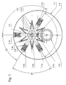
- Figure 3 shows a third embodiment of the detector, with the same components as in Fig. 2, but in another geometric arrangement. To illustrate this, is the first digit of the respective reference instead of "2" here "3".
- the two LEDs and the two photodiodes are not reversed be arranged, because in this case would the two photodiodes simultaneously the forward scattered radiation the one LED and then the reverse scattered radiation the other LED measure, so four Deliver readings, but two in pairs at least approximately the same.
- the stray radiation measured at angles of 120 ° and 60 °, respectively.
- compliance with these angles is not necessary Condition for carrying out the proposed with the invention Process.
- the only important thing is that the Angle be chosen so that in forward scatter direction and sufficient in reverse direction on the one hand high intensities, on the other hand for as many different Brand-following products sufficiently different Intensities in the forward scattering area and in the backward scattering area of the particles concerned.
Landscapes
- Chemical & Material Sciences (AREA)
- Analytical Chemistry (AREA)
- Business, Economics & Management (AREA)
- Emergency Management (AREA)
- Physics & Mathematics (AREA)
- General Physics & Mathematics (AREA)
- Fire-Detection Mechanisms (AREA)
- Investigating Or Analysing Materials By Optical Means (AREA)
- Fire Alarms (AREA)
Abstract
Description
- Fig. 1
- eine in Höhe der optischen Achsen geschnittene Aufsicht auf die die Messkammer tragende Grundplatte des Brandmelders in einer ersten Ausführungsform
- Fig. 2
- die entsprechende Ansicht einer zweiten Ausführungsform und
- Fig. 3
- die entsprechende Ansicht einer dritten Ausführungsform.
Claims (19)
- Verfahren zur Branderkennung nach dem Streulichtprinzip durch gepulste Einstrahlung einer Strahlung einer ersten Wellenlänge längs einer ersten Strahlungsachse sowie einer Strahlung einer zweiten, demgegenüber kürzeren Wellenlänge längs einer zweiten Strahlungsachse in ein Messvolumen und Messung der an in dem Messvolumen befindlichen Partikeln gestreuten Strahlungen unter einem Vorwärtsstreuwinkel von mehr als 90° und unter einem Rückwärtsstreuwinkel von weniger als 90°, dadurch gekennzeichnet, dass die Vorwärtsstreustrahlungen und die Rückwärtsstreustrahlungen der ersten und der zweiten Wellenlänge getrennt voneinander gemessen und ausgewertet werden.
- Verfahren nach Anspruch 1, dadurch gekennzeichnet, dass von den Signalpegeln, die den vier gemessenen Intensitäten der Streustrahlungen entsprechen, die korrespondierenden Ruhewertpegel, multipliziert mit einem Faktor ≤1, subtrahiert werden, dass die Ergebniswerte gewichtet werden und dass die gewichteten Werte in einer Auswertelogik verrechnet, mit gespeicherten Werten verglichen, die Vergleichsergebnisse verknüpft und bewertet werden sowie ergebnisabhängig mindestens ein Alarmsignal erzeugt wird.
- Verfahren nach Anspruch 2, dadurch gekennzeichnet, dass das Verhältnis zwischen den gewichteten Werten der Vorwärtsstreustrahlungsintensität und der Rückwärtsstreustrahlungsintensität der ersten Wellenlänge und das Verhältnis zwischen den gewichteten Werten der Vorwärtsstreustrahlungsintensität und der Rückwärtsstreustrahlungsintensität der zweiten Wellenlänge gebildet werden, und dass die ermittelten Verhältniswerte in einer Auswertelogik verrechnet, mit gespeicherten Werten verglichen, die Vergleichsergebnisse verknüpft und bewertet werden sowie ergebnisabhängig mindestens ein Alarmsignal erzeugt wird.
- Verfahren nach einem der Anspruch 2 oder 3, dadurch gekennzeichnet, dass das Verhältnis der gewichteten Werte der Vorwärtsstreustrahlungsintensitäten der ersten und der zweiten Wellenlänge zueinander und das Verhältnis der gewichteten Werte der Rückwärtsstreustrahlungsintensitäten der ersten und der zweiten Wellenlänge zueinander gebildet werden, und die ermittelten Verhältniswerte in einer Auswertelogik verrechnet, mit gespeicherten Werten verglichen, die Vergleichsergebnisse verknüpft und bewertet werden sowie ergebnisabhängig mindestens ein Alarmsignal erzeugt wird.
- Verfahren nach Anspruch 3 oder 4, dadurch gekennzeichnet, dass die ermittelten Verhältniswerte ihrerseits ins Verhältnis gesetzt werden und das Resultat mit gespeicherten Werten verglichen sowie das Vergleichsergebnis bei der Weiterverarbeitung berücksichtigt wird.
- Verfahren nach einem der Ansprüche 1 bis 5, dadurch gekennzeichnet, dass die Vorwärtsstreustrahlungen der ersten und der zweiten Wellenlänge unter dem gleichen Vorwärtsstreuwinkel sowie die Rückwärtsstreustrahlungen der ersten und der zweiten Wellenlänge unter dem gleichen Rückwärtsstreuwinkel gemessen werden.
- Verfahren nach einem der Ansprüche 1 bis 6, dadurch gekennzeichnet, dass die Streustrahlungen der ersten und der zweiten Wellenlänge auf gegenüberliegenden Seiten der Messkammer auf der gleichen Hauptachse gemessen werden.
- Verfahren nach einem der Ansprüche 1 bis 7, dadurch gekennzeichnet, dass die Strahlungen der ersten und der zweiten Wellenlänge von gegenüberliegenden Seiten längs zusammenfallender Strahlungsachsen in das Messvolumen eingestrahlt werden.
- Verfahren nach einem der Ansprüche 1 bis 8, dadurch gekennzeichnet, dass die erste Wellenlänge und die zweite Wellenlänge so gewählt werden, dass sie nicht in einem ganzzahligen Verhältnis zueinander stehen.
- Verfahren nach einem der Ansprüche 1 bis 9, dadurch gekennzeichnet, dass die erste Wellenlänge im Bereich der Infrarotstrahlung liegt und dass die zweite Wellenlänge im Bereich des blauen Lichts oder der ultravioletten Strahlung liegt.
- Verfahren nach einem der Ansprüche 1 bis 10, dadurch gekennzeichnet, dass die erste Wellenlänge im Bereich von 880 nm liegt und dass die zweite Wellenlänge im Bereich von 475 nm, alternativ 370 nm liegt.
- Verfahren nach einem der Ansprüche 1 bis 11, dadurch gekennzeichnet, dass das Puls/Pause-Verhältnis der Strahlung der ersten und der zweiten Wellenlänge größer als 1:10000 und vorzugsweise im Bereich von 1:20000 gewählt wird.
- Streulicht-Brandmelder mit einer mit der Umgebungsluft kommunizierenden Messkammer, die ein Messvolumen begrenzt, in das eine infrarotstrahlende und eine blaustrahlende LED aus unterschiedlichen Richtungen einstrahlen und die an in dem Messvolumen befindlichen Partikeln gestreute Strahlung fotoelektrisch gemessen und ausgewertet wird, dadurch gekennzeichnet, dass der Melder zwei Fotoempfänger umfasst, dass die zwei Fotoempfänger sich in Bezug auf das Messvolumen gegenüber auf einer gemeinsamen Hauptachse liegen und dass die Strahlungsachsen der zwei LEDs mit dieser Hauptachse einen spitzen Winkel von weniger als 90° einschließen und sich in einem auf der Hauptachse liegenen Punkt schneiden, der im Zentrum des Messvolumens liegt.
- Melder nach Anspruch 13, dadurch gekennzeichnet, dass die LEDs auf der gleichen Seite der Hauptachse angeordnet sind.
- Melder nach Anspruch 13, dadurch gekennzeichnet, dass die LEDs symmetrisch zu der Hauptachse angeordnet sind.
- Melder nach Anspruch 13 oder 15, dadurch gekennzeichnet, dass die LEDs punktsymmetrisch zu dem Zentrum des Messvolumens angeordnet sind, so dass ihre Strahlungsachsen zusammenfallen.
- Melder nach einem der Ansprüche 13 bis 16, dadurch gekennzeichnet, dass die Strahlungsachsen der LEDs mit der Hauptachse jeweils einen spitzen Winkel von etwa 60° einschließen.
- Melder nach einem der Ansprüche 13 bis 17, dadurch gekennzeichnet, dass jede LED und jeder Fotoempfänger in einem eigenen Tubus sitzt, und dass in der Messkammer, außerhalb des Messvolumens, zwischen den LEDs und den Fotoempfängern Blenden und Strahlungsfallen angeordnet sind.
- Melder nach einem der Ansprüche 13 oder 15 bis 18, dadurch gekennzeichnet, dass der erste Fotoempfänger die Vorwärtsstreustrahlung der infrarotstrahlenden LED und die Rückwärtsstreustrahlung der blaustrahlenden LED sowie der zweite Fotoempfänger die Rückwärtsstreustrahlung der infrarotstrahlenden LED und die Vorwärtsstreustrahlung der blaustrahlenden LED empfängt.
Applications Claiming Priority (2)
| Application Number | Priority Date | Filing Date | Title |
|---|---|---|---|
| DE10246756A DE10246756B4 (de) | 2002-10-07 | 2002-10-07 | Branderkennungsverfahren und Brandmelder zu dessen Durchführung |
| DE10246756 | 2002-10-07 |
Publications (3)
| Publication Number | Publication Date |
|---|---|
| EP1408469A2 true EP1408469A2 (de) | 2004-04-14 |
| EP1408469A3 EP1408469A3 (de) | 2004-07-14 |
| EP1408469B1 EP1408469B1 (de) | 2009-05-27 |
Family
ID=32010359
Family Applications (1)
| Application Number | Title | Priority Date | Filing Date |
|---|---|---|---|
| EP03013270A Expired - Lifetime EP1408469B1 (de) | 2002-10-07 | 2003-06-12 | Branderkennungsverfahren und Brandmelder zu dessen Durchführung |
Country Status (6)
| Country | Link |
|---|---|
| US (2) | US7239387B2 (de) |
| EP (1) | EP1408469B1 (de) |
| AT (1) | ATE432518T1 (de) |
| DE (2) | DE10246756B4 (de) |
| ES (1) | ES2326631T3 (de) |
| TW (1) | TW200532593A (de) |
Cited By (8)
| Publication number | Priority date | Publication date | Assignee | Title |
|---|---|---|---|---|
| EP1879158A1 (de) * | 2006-07-14 | 2008-01-16 | Siemens Schweiz AG | Verfahren zur Detektion von Rauch und optischer Rauchmelder |
| WO2008006578A1 (de) | 2006-07-12 | 2008-01-17 | Hochschule Für Technik Und Wirtschaft Des Saarlandes | Vorrichtung und verfahren zur unterscheidung von nebelarten |
| EP1887536A1 (de) * | 2006-08-09 | 2008-02-13 | Siemens Schweiz AG | Streulicht-Rauchmelder |
| EP2706515A1 (de) * | 2012-09-07 | 2014-03-12 | Amrona AG | Vorrichtung und Verfahren zum Detektieren von Streulichtsignalen |
| DE202015000820U1 (de) | 2014-12-01 | 2015-03-04 | Siemens Schweiz Ag | Streulichtrauchmelder mit zwei zweifarbigen Leuchtdioden und einem gemeinsamen Photosensor oder mit einer zweifarbigen Leuchtdiode und mit zwei Photosensoren jeweils in einer Vorwärts- und Rückwärtsstreulichtanordnung |
| US9036150B2 (en) | 2011-11-25 | 2015-05-19 | Apparatebau Gauting Gmbh | Scattered radiation fire detector and method for the automatic detection of a fire situation |
| EP3287999A1 (de) | 2016-08-25 | 2018-02-28 | Siemens Schweiz AG | Verfahren zur branddetektion nach dem streulichtprinzip mit gestaffelter zuschaltung einer weiteren led-einheit zum einstrahlen weiterer lichtimpulse unterschiedlicher wellenlänge und streulichtwinkel sowie derartige streulichtrauchmelder |
| EP3321906A1 (de) * | 2016-11-11 | 2018-05-16 | Kidde Technologies, Inc. | Auf hochempfindlicher faseroptik basierende detektion |
Families Citing this family (31)
| Publication number | Priority date | Publication date | Assignee | Title |
|---|---|---|---|---|
| US7111496B1 (en) * | 2004-04-29 | 2006-09-26 | Pedro Lilienfeld | Methods and apparatus for monitoring a mass concentration of particulate matter |
| EP1619640A1 (de) * | 2004-07-23 | 2006-01-25 | Siemens Schweiz AG | Streulichtrauchmelder |
| EP1630758B1 (de) * | 2004-08-31 | 2008-01-02 | Siemens Schweiz AG | Streulicht-Rauchmelder |
| DE102007013295A1 (de) | 2007-03-16 | 2008-09-18 | Aoa Apparatebau Gauting Gmbh | Rauchmelder |
| AU2015224408B2 (en) * | 2008-09-05 | 2016-05-26 | Garrett Thermal Systems Limited | Optical detection of particle characteristics |
| EP2331938A4 (de) | 2008-09-05 | 2017-05-17 | Xtralis Technologies Ltd | Optischer nachweis von partikeleigenschaften |
| US8717181B2 (en) | 2010-07-29 | 2014-05-06 | Hill-Rom Services, Inc. | Bed exit alert silence with automatic re-enable |
| JP5853143B2 (ja) * | 2011-03-11 | 2016-02-09 | パナソニックIpマネジメント株式会社 | 火災感知器 |
| DE102011108389A1 (de) | 2011-07-22 | 2013-01-24 | PPP "KB Pribor" Ltd. | Rauchdetektor |
| DE102011108390B4 (de) | 2011-07-22 | 2019-07-11 | PPP "KB Pribor" Ltd. | Verfahren zur Herstellung eines Rauchdetektors vom offenen Typ |
| GB2499256A (en) * | 2012-02-13 | 2013-08-14 | Thorn Security | Fire detector sensing photo-luminescent emissions from illuminated particles |
| US8952821B2 (en) * | 2012-04-29 | 2015-02-10 | Valor Fire Safety, Llc | Smoke detector utilizing ambient-light sensor, external sampling volume, and internally reflected light |
| DE102013201049A1 (de) * | 2013-01-23 | 2014-07-24 | Robert Bosch Gmbh | Brandmelder |
| KR20160079057A (ko) | 2013-10-30 | 2016-07-05 | 발로르 파이어 세이프티, 엘엘씨 | 외부 샘플링 볼륨 및 주변광 배제를 갖는 연기 감지기 |
| US9355542B2 (en) * | 2014-01-27 | 2016-05-31 | Kidde Technologies, Inc. | Apparatuses, systems and methods for self-testing optical fire detectors |
| EP3029646B1 (de) * | 2014-12-01 | 2019-01-30 | Siemens Schweiz AG | Streulichtrauchmelder mit einer zweifarbigen Leuchtdiode |
| CN106663357B (zh) * | 2015-06-23 | 2019-01-22 | 华中科技大学 | 一种基于双波长散射信号的气溶胶特征参数传感方法及其应用 |
| MX389745B (es) * | 2016-06-15 | 2025-03-20 | Carrier Corp | Metodología de detección de humo. |
| WO2018027104A1 (en) * | 2016-08-04 | 2018-02-08 | Carrier Corporation | Smoke detector |
| WO2018226567A1 (en) | 2017-06-09 | 2018-12-13 | Carrier Corporation | Chamberless smoke detector with indoor air quality detection and monitoring |
| CN110675590A (zh) * | 2018-07-03 | 2020-01-10 | 秦皇岛尼特智能科技有限公司 | 一种火灾烟雾探测用复合式迷宫结构及装配方法 |
| JP7320959B2 (ja) | 2019-03-11 | 2023-08-04 | 能美防災株式会社 | 煙感知器 |
| US10697880B1 (en) * | 2019-04-07 | 2020-06-30 | Everday Technology Co., Ltd. | Smoke detecting device |
| CN109949534A (zh) * | 2019-04-19 | 2019-06-28 | 汉威科技集团股份有限公司 | 一种多光路双向散射感烟探测器迷宫 |
| US10950108B2 (en) * | 2019-08-09 | 2021-03-16 | Rosemount Aerospace Inc. | Characterization of aerosols |
| CN112562253B (zh) * | 2019-09-26 | 2022-06-03 | 杭州海康消防科技有限公司 | 一种烟雾传感器、烟雾报警方法及装置 |
| US11127284B1 (en) * | 2020-07-02 | 2021-09-21 | Honeywell International Inc. | Self-calibrating fire sensing device |
| US11506586B2 (en) | 2020-08-17 | 2022-11-22 | Carrier Corporation | Photoelectric smoke sensor tube |
| CN112991666B (zh) * | 2021-02-08 | 2023-04-28 | 三明学院 | 一种火灾烟雾探测器及其烟室和抗干扰烟雾探测方法 |
| JP7728089B2 (ja) * | 2021-03-10 | 2025-08-22 | ホーチキ株式会社 | 火災検出装置、防災設備及び火災検出方法 |
| WO2024149768A1 (en) | 2023-01-12 | 2024-07-18 | ams Sensors Germany GmbH | Smoke detector and method for smoke detection |
Family Cites Families (18)
| Publication number | Priority date | Publication date | Assignee | Title |
|---|---|---|---|---|
| US3982130A (en) * | 1975-10-10 | 1976-09-21 | The United States Of America As Represented By The Secretary Of The Air Force | Ultraviolet wavelength smoke detector |
| SE7905294L (sv) * | 1979-06-15 | 1980-12-16 | Svenska Traeforskningsinst | Stoftmetning |
| US5051595A (en) * | 1989-12-06 | 1991-09-24 | Santa Barbara Research Center | Fiber optic flame detection and temperature measurement system employing doped optical fiber |
| GB2259763B (en) * | 1991-09-20 | 1995-05-31 | Hochiki Co | Fire alarm system |
| US5352901A (en) * | 1993-04-26 | 1994-10-04 | Cummins Electronics Company, Inc. | Forward and back scattering loss compensated smoke detector |
| US5575837A (en) * | 1993-04-28 | 1996-11-19 | Fujimi Incorporated | Polishing composition |
| US5527423A (en) * | 1994-10-06 | 1996-06-18 | Cabot Corporation | Chemical mechanical polishing slurry for metal layers |
| EP0852615B1 (de) * | 1996-07-25 | 2005-12-14 | DuPont Air Products NanoMaterials L.L.C. | Zusammensetzung und verfahren zum chemisch-mechanischen polieren |
| US5958288A (en) * | 1996-11-26 | 1999-09-28 | Cabot Corporation | Composition and slurry useful for metal CMP |
| JPH1123458A (ja) * | 1997-05-08 | 1999-01-29 | Nittan Co Ltd | 煙感知器および監視制御システム |
| US6001269A (en) * | 1997-05-20 | 1999-12-14 | Rodel, Inc. | Method for polishing a composite comprising an insulator, a metal, and titanium |
| US6083419A (en) * | 1997-07-28 | 2000-07-04 | Cabot Corporation | Polishing composition including an inhibitor of tungsten etching |
| EP1101210A1 (de) * | 1998-07-31 | 2001-05-23 | Dunstan Walter Runciman | Rauchdetektoren |
| DE19902319B4 (de) * | 1999-01-21 | 2011-06-30 | Novar GmbH, Albstadt-Ebingen Zweigniederlassung Neuss, 41469 | Streulichtbrandmelder |
| US7126687B2 (en) * | 1999-08-09 | 2006-10-24 | The United States Of America As Represented By The Secretary Of The Army | Method and instrumentation for determining absorption and morphology of individual airborne particles |
| AUPQ553800A0 (en) * | 2000-02-10 | 2000-03-02 | Cole, Martin Terence | Improvements relating to smoke detectors particularily duct monitored smoke detectors |
| JP4954398B2 (ja) * | 2001-08-09 | 2012-06-13 | 株式会社フジミインコーポレーテッド | 研磨用組成物およびそれを用いた研磨方法 |
| GB2397122B (en) | 2003-01-03 | 2006-02-08 | David Appleby | Fire detector with low false alarm rate |
-
2002
- 2002-10-07 DE DE10246756A patent/DE10246756B4/de not_active Expired - Lifetime
-
2003
- 2003-06-12 ES ES03013270T patent/ES2326631T3/es not_active Expired - Lifetime
- 2003-06-12 EP EP03013270A patent/EP1408469B1/de not_active Expired - Lifetime
- 2003-06-12 DE DE50311545T patent/DE50311545D1/de not_active Expired - Lifetime
- 2003-06-12 AT AT03013270T patent/ATE432518T1/de active
- 2003-08-26 US US10/647,318 patent/US7239387B2/en not_active Expired - Lifetime
-
2004
- 2004-03-16 TW TW093106965A patent/TW200532593A/zh unknown
-
2007
- 2007-06-07 US US11/759,264 patent/US7298479B2/en not_active Expired - Lifetime
Cited By (19)
| Publication number | Priority date | Publication date | Assignee | Title |
|---|---|---|---|---|
| WO2008006578A1 (de) | 2006-07-12 | 2008-01-17 | Hochschule Für Technik Und Wirtschaft Des Saarlandes | Vorrichtung und verfahren zur unterscheidung von nebelarten |
| EP1879158A1 (de) * | 2006-07-14 | 2008-01-16 | Siemens Schweiz AG | Verfahren zur Detektion von Rauch und optischer Rauchmelder |
| EP1887536A1 (de) * | 2006-08-09 | 2008-02-13 | Siemens Schweiz AG | Streulicht-Rauchmelder |
| WO2008017698A1 (de) * | 2006-08-09 | 2008-02-14 | Siemens Schweiz Ag | Streulicht-rauchmelder |
| US9036150B2 (en) | 2011-11-25 | 2015-05-19 | Apparatebau Gauting Gmbh | Scattered radiation fire detector and method for the automatic detection of a fire situation |
| EP2706515A1 (de) * | 2012-09-07 | 2014-03-12 | Amrona AG | Vorrichtung und Verfahren zum Detektieren von Streulichtsignalen |
| US9244010B2 (en) | 2012-09-07 | 2016-01-26 | Amrona Ag | Device and method for detecting scattered light signals |
| CN103782327A (zh) * | 2012-09-07 | 2014-05-07 | 艾摩罗那股份公司 | 用于检测散射光信号的设备和方法 |
| WO2014037520A1 (de) * | 2012-09-07 | 2014-03-13 | Amrona Ag | Vorrichtung und verfahren zum detektieren von streulichtsignalen |
| EP2839448B1 (de) | 2012-09-07 | 2015-07-22 | Amrona AG | Vorrichtung und verfahren zum detektieren von streulichtsignalen |
| CN103782327B (zh) * | 2012-09-07 | 2015-08-05 | 艾摩罗那股份公司 | 用于检测散射光信号的设备和方法 |
| EP3029648A1 (de) | 2014-12-01 | 2016-06-08 | Siemens Schweiz AG | Streulichtrauchmelder mit zwei zweifarbigen Leuchtdioden und einem gemeinsamen Photosensor oder mit einer zweifarbigen Leuchtdiode und mit zwei Photosensoren jeweils in einer Vorwärts- und Rückwärtsstreulichtanordnung |
| DE202015000820U1 (de) | 2014-12-01 | 2015-03-04 | Siemens Schweiz Ag | Streulichtrauchmelder mit zwei zweifarbigen Leuchtdioden und einem gemeinsamen Photosensor oder mit einer zweifarbigen Leuchtdiode und mit zwei Photosensoren jeweils in einer Vorwärts- und Rückwärtsstreulichtanordnung |
| EP3287999A1 (de) | 2016-08-25 | 2018-02-28 | Siemens Schweiz AG | Verfahren zur branddetektion nach dem streulichtprinzip mit gestaffelter zuschaltung einer weiteren led-einheit zum einstrahlen weiterer lichtimpulse unterschiedlicher wellenlänge und streulichtwinkel sowie derartige streulichtrauchmelder |
| WO2018036754A1 (de) | 2016-08-25 | 2018-03-01 | Siemens Schweiz Ag | Verfahren zur branddetektion nach dem streulichtprinzip mit gestaffelter zuschaltung einer weiteren led-einheit zum einstrahlen weiterer lichtimpulse unterschiedlicher wellenlänge und streulichtwinkel sowie derartige streulichtrauchmelder |
| CN109601019A (zh) * | 2016-08-25 | 2019-04-09 | 西门子瑞士有限公司 | 用于根据散射光原理、借助用于使不同波长和散射光角度的另外的光脉冲入射的另外的led单元交错地接通来进行火灾探测的方法以及这样的散射光烟雾报警器 |
| US10685546B2 (en) | 2016-08-25 | 2020-06-16 | Siemens Schweiz Ag | Fire detection using the scattered light principle with a staggered activation of a further LED unit for radiating in further light pulses with different wavelengths and scattered light angles |
| EP3321906A1 (de) * | 2016-11-11 | 2018-05-16 | Kidde Technologies, Inc. | Auf hochempfindlicher faseroptik basierende detektion |
| CN108072596A (zh) * | 2016-11-11 | 2018-05-25 | 基德科技公司 | 基于高灵敏度光纤的检测 |
Also Published As
| Publication number | Publication date |
|---|---|
| US7298479B2 (en) | 2007-11-20 |
| ATE432518T1 (de) | 2009-06-15 |
| US20040066512A1 (en) | 2004-04-08 |
| TW200532593A (en) | 2005-10-01 |
| ES2326631T3 (es) | 2009-10-16 |
| EP1408469A3 (de) | 2004-07-14 |
| EP1408469B1 (de) | 2009-05-27 |
| US7239387B2 (en) | 2007-07-03 |
| HK1060426A1 (zh) | 2004-08-06 |
| DE10246756B4 (de) | 2006-03-16 |
| DE50311545D1 (de) | 2009-07-09 |
| DE10246756A1 (de) | 2004-04-22 |
| US20070229824A1 (en) | 2007-10-04 |
Similar Documents
| Publication | Publication Date | Title |
|---|---|---|
| EP1408469B1 (de) | Branderkennungsverfahren und Brandmelder zu dessen Durchführung | |
| DE60315449T2 (de) | Rauchmelder | |
| EP2839448B1 (de) | Vorrichtung und verfahren zum detektieren von streulichtsignalen | |
| DE102011119431B4 (de) | Streustrahlungsbrandmelder und Verfahren zur automatischen Erkennung einer Brandsituation | |
| DE3831654C2 (de) | ||
| EP3504692B1 (de) | Verfahren zur branddetektion nach dem streulichtprinzip mit gestaffelter zuschaltung einer weiteren led-einheit zum einstrahlen weiterer lichtimpulse unterschiedlicher wellenlänge und streulichtwinkel sowie derartige streulichtrauchmelder | |
| EP3504535B1 (de) | Messvorrichtung zur absorptionsmessung von gasen | |
| DE19809896A1 (de) | Brandmelder | |
| DE2504300B2 (de) | Vorrichtung zur Messung des Absorptionsvermögens eines Mediums, insbesondere von Rauch | |
| DE102014016515B4 (de) | Optischer Gassensor | |
| DE102015002465A1 (de) | Verfahren zur Feinstaubmessung und Feinstaubsensor zur Bestimmung der Partikelgröße von Feinstaub | |
| DE19741853A1 (de) | Rauchmelder | |
| DE112020002849T5 (de) | Optischer Partikelsensor | |
| EP3096130B1 (de) | Vorrichtung zur identifikation von aerosolen | |
| CH711170A1 (de) | Verfahren und Vorrichtung zur Detektion von Aerosolpartikeln. | |
| DE102018131128A1 (de) | Optischer Sensor | |
| EP3704473A1 (de) | Neuartiger sensor für die ramanspektroskopie | |
| DE3917571C2 (de) | ||
| DE102006048839B4 (de) | Photoakustische Gassensor-Vorrichtung mit mehreren Messzellen | |
| EP4043870A1 (de) | Vorrichtung und verfahren zur ermittlung des verschmutzungsgrades einer oberfläche eines solarmoduls | |
| DE29622293U1 (de) | Optischer Rauchmelder | |
| DE3018021C2 (de) | ||
| DE102011077290B4 (de) | Messverfahren und Messvorrichtung zur Ermittlung von Transmissions- und/oder Reflexionseigenschaften | |
| DE102020202824A1 (de) | Sensorvorrichtung unter verwendung der winkelabhängigkeit eines dichroitischen filters | |
| DE102017220461A1 (de) | Partikelsensor |
Legal Events
| Date | Code | Title | Description |
|---|---|---|---|
| PUAI | Public reference made under article 153(3) epc to a published international application that has entered the european phase |
Free format text: ORIGINAL CODE: 0009012 |
|
| AK | Designated contracting states |
Kind code of ref document: A2 Designated state(s): AT BE BG CH CY CZ DE DK EE ES FI FR GB GR HU IE IT LI LU MC NL PT RO SE SI SK TR |
|
| AX | Request for extension of the european patent |
Extension state: AL LT LV MK |
|
| PUAL | Search report despatched |
Free format text: ORIGINAL CODE: 0009013 |
|
| AK | Designated contracting states |
Kind code of ref document: A3 Designated state(s): AT BE BG CH CY CZ DE DK EE ES FI FR GB GR HU IE IT LI LU MC NL PT RO SE SI SK TR |
|
| AX | Request for extension of the european patent |
Extension state: AL LT LV MK |
|
| REG | Reference to a national code |
Ref country code: HK Ref legal event code: DE Ref document number: 1060426 Country of ref document: HK |
|
| 17P | Request for examination filed |
Effective date: 20040715 |
|
| AKX | Designation fees paid |
Designated state(s): AT BE BG CH CY CZ DE DK EE ES FI FR GB GR HU IE IT LI LU MC NL PT RO SE SI SK TR |
|
| 17Q | First examination report despatched |
Effective date: 20060802 |
|
| GRAP | Despatch of communication of intention to grant a patent |
Free format text: ORIGINAL CODE: EPIDOSNIGR1 |
|
| GRAS | Grant fee paid |
Free format text: ORIGINAL CODE: EPIDOSNIGR3 |
|
| GRAA | (expected) grant |
Free format text: ORIGINAL CODE: 0009210 |
|
| AK | Designated contracting states |
Kind code of ref document: B1 Designated state(s): AT BE BG CH CY CZ DE DK EE ES FI FR GB GR HU IE IT LI LU MC NL PT RO SE SI SK TR |
|
| REG | Reference to a national code |
Ref country code: GB Ref legal event code: FG4D Free format text: NOT ENGLISH |
|
| REG | Reference to a national code |
Ref country code: CH Ref legal event code: EP |
|
| REG | Reference to a national code |
Ref country code: IE Ref legal event code: FG4D Free format text: LANGUAGE OF EP DOCUMENT: GERMAN |
|
| REF | Corresponds to: |
Ref document number: 50311545 Country of ref document: DE Date of ref document: 20090709 Kind code of ref document: P |
|
| REG | Reference to a national code |
Ref country code: HK Ref legal event code: GR Ref document number: 1060426 Country of ref document: HK |
|
| REG | Reference to a national code |
Ref country code: ES Ref legal event code: FG2A Ref document number: 2326631 Country of ref document: ES Kind code of ref document: T3 |
|
| PG25 | Lapsed in a contracting state [announced via postgrant information from national office to epo] |
Ref country code: PT Free format text: LAPSE BECAUSE OF FAILURE TO SUBMIT A TRANSLATION OF THE DESCRIPTION OR TO PAY THE FEE WITHIN THE PRESCRIBED TIME-LIMIT Effective date: 20090927 Ref country code: FI Free format text: LAPSE BECAUSE OF FAILURE TO SUBMIT A TRANSLATION OF THE DESCRIPTION OR TO PAY THE FEE WITHIN THE PRESCRIBED TIME-LIMIT Effective date: 20090527 |
|
| NLV1 | Nl: lapsed or annulled due to failure to fulfill the requirements of art. 29p and 29m of the patents act | ||
| PG25 | Lapsed in a contracting state [announced via postgrant information from national office to epo] |
Ref country code: SI Free format text: LAPSE BECAUSE OF FAILURE TO SUBMIT A TRANSLATION OF THE DESCRIPTION OR TO PAY THE FEE WITHIN THE PRESCRIBED TIME-LIMIT Effective date: 20090527 Ref country code: SE Free format text: LAPSE BECAUSE OF FAILURE TO SUBMIT A TRANSLATION OF THE DESCRIPTION OR TO PAY THE FEE WITHIN THE PRESCRIBED TIME-LIMIT Effective date: 20090827 Ref country code: NL Free format text: LAPSE BECAUSE OF FAILURE TO SUBMIT A TRANSLATION OF THE DESCRIPTION OR TO PAY THE FEE WITHIN THE PRESCRIBED TIME-LIMIT Effective date: 20090527 |
|
| BERE | Be: lapsed |
Owner name: NOVAR G.M.B.H. Effective date: 20090630 |
|
| REG | Reference to a national code |
Ref country code: IE Ref legal event code: FD4D |
|
| PG25 | Lapsed in a contracting state [announced via postgrant information from national office to epo] |
Ref country code: EE Free format text: LAPSE BECAUSE OF FAILURE TO SUBMIT A TRANSLATION OF THE DESCRIPTION OR TO PAY THE FEE WITHIN THE PRESCRIBED TIME-LIMIT Effective date: 20090527 Ref country code: DK Free format text: LAPSE BECAUSE OF FAILURE TO SUBMIT A TRANSLATION OF THE DESCRIPTION OR TO PAY THE FEE WITHIN THE PRESCRIBED TIME-LIMIT Effective date: 20090527 Ref country code: CZ Free format text: LAPSE BECAUSE OF FAILURE TO SUBMIT A TRANSLATION OF THE DESCRIPTION OR TO PAY THE FEE WITHIN THE PRESCRIBED TIME-LIMIT Effective date: 20090527 Ref country code: IE Free format text: LAPSE BECAUSE OF FAILURE TO SUBMIT A TRANSLATION OF THE DESCRIPTION OR TO PAY THE FEE WITHIN THE PRESCRIBED TIME-LIMIT Effective date: 20090527 Ref country code: MC Free format text: LAPSE BECAUSE OF NON-PAYMENT OF DUE FEES Effective date: 20090630 Ref country code: RO Free format text: LAPSE BECAUSE OF FAILURE TO SUBMIT A TRANSLATION OF THE DESCRIPTION OR TO PAY THE FEE WITHIN THE PRESCRIBED TIME-LIMIT Effective date: 20090527 |
|
| REG | Reference to a national code |
Ref country code: CH Ref legal event code: PL |
|
| PG25 | Lapsed in a contracting state [announced via postgrant information from national office to epo] |
Ref country code: SK Free format text: LAPSE BECAUSE OF FAILURE TO SUBMIT A TRANSLATION OF THE DESCRIPTION OR TO PAY THE FEE WITHIN THE PRESCRIBED TIME-LIMIT Effective date: 20090527 |
|
| PG25 | Lapsed in a contracting state [announced via postgrant information from national office to epo] |
Ref country code: BG Free format text: LAPSE BECAUSE OF FAILURE TO SUBMIT A TRANSLATION OF THE DESCRIPTION OR TO PAY THE FEE WITHIN THE PRESCRIBED TIME-LIMIT Effective date: 20090827 |
|
| PLBE | No opposition filed within time limit |
Free format text: ORIGINAL CODE: 0009261 |
|
| STAA | Information on the status of an ep patent application or granted ep patent |
Free format text: STATUS: NO OPPOSITION FILED WITHIN TIME LIMIT |
|
| PG25 | Lapsed in a contracting state [announced via postgrant information from national office to epo] |
Ref country code: CH Free format text: LAPSE BECAUSE OF NON-PAYMENT OF DUE FEES Effective date: 20090630 Ref country code: LI Free format text: LAPSE BECAUSE OF NON-PAYMENT OF DUE FEES Effective date: 20090630 |
|
| 26N | No opposition filed |
Effective date: 20100302 |
|
| PG25 | Lapsed in a contracting state [announced via postgrant information from national office to epo] |
Ref country code: BE Free format text: LAPSE BECAUSE OF NON-PAYMENT OF DUE FEES Effective date: 20090630 |
|
| PG25 | Lapsed in a contracting state [announced via postgrant information from national office to epo] |
Ref country code: GR Free format text: LAPSE BECAUSE OF FAILURE TO SUBMIT A TRANSLATION OF THE DESCRIPTION OR TO PAY THE FEE WITHIN THE PRESCRIBED TIME-LIMIT Effective date: 20090828 |
|
| PG25 | Lapsed in a contracting state [announced via postgrant information from national office to epo] |
Ref country code: LU Free format text: LAPSE BECAUSE OF NON-PAYMENT OF DUE FEES Effective date: 20090612 |
|
| PG25 | Lapsed in a contracting state [announced via postgrant information from national office to epo] |
Ref country code: HU Free format text: LAPSE BECAUSE OF FAILURE TO SUBMIT A TRANSLATION OF THE DESCRIPTION OR TO PAY THE FEE WITHIN THE PRESCRIBED TIME-LIMIT Effective date: 20091128 |
|
| PG25 | Lapsed in a contracting state [announced via postgrant information from national office to epo] |
Ref country code: TR Free format text: LAPSE BECAUSE OF FAILURE TO SUBMIT A TRANSLATION OF THE DESCRIPTION OR TO PAY THE FEE WITHIN THE PRESCRIBED TIME-LIMIT Effective date: 20090527 |
|
| PG25 | Lapsed in a contracting state [announced via postgrant information from national office to epo] |
Ref country code: CY Free format text: LAPSE BECAUSE OF FAILURE TO SUBMIT A TRANSLATION OF THE DESCRIPTION OR TO PAY THE FEE WITHIN THE PRESCRIBED TIME-LIMIT Effective date: 20090527 |
|
| REG | Reference to a national code |
Ref country code: DE Ref legal event code: R082 Ref document number: 50311545 Country of ref document: DE Representative=s name: PATENTANWAELTE HENKEL, BREUER & PARTNER, DE Ref country code: DE Ref legal event code: R082 Ref document number: 50311545 Country of ref document: DE Representative=s name: PATENTANWAELTE HENKEL, BREUER & PARTNER MBB, DE |
|
| REG | Reference to a national code |
Ref country code: FR Ref legal event code: PLFP Year of fee payment: 14 |
|
| REG | Reference to a national code |
Ref country code: FR Ref legal event code: PLFP Year of fee payment: 15 |
|
| REG | Reference to a national code |
Ref country code: FR Ref legal event code: PLFP Year of fee payment: 16 |
|
| PGFP | Annual fee paid to national office [announced via postgrant information from national office to epo] |
Ref country code: IT Payment date: 20180625 Year of fee payment: 9 Ref country code: ES Payment date: 20180723 Year of fee payment: 16 |
|
| REG | Reference to a national code |
Ref country code: AT Ref legal event code: MM01 Ref document number: 432518 Country of ref document: AT Kind code of ref document: T Effective date: 20190612 |
|
| PG25 | Lapsed in a contracting state [announced via postgrant information from national office to epo] |
Ref country code: AT Free format text: LAPSE BECAUSE OF NON-PAYMENT OF DUE FEES Effective date: 20190612 Ref country code: IT Free format text: LAPSE BECAUSE OF NON-PAYMENT OF DUE FEES Effective date: 20190612 |
|
| PGFP | Annual fee paid to national office [announced via postgrant information from national office to epo] |
Ref country code: FR Payment date: 20200626 Year of fee payment: 18 |
|
| REG | Reference to a national code |
Ref country code: ES Ref legal event code: FD2A Effective date: 20201027 |
|
| PGFP | Annual fee paid to national office [announced via postgrant information from national office to epo] |
Ref country code: DE Payment date: 20200630 Year of fee payment: 18 |
|
| PG25 | Lapsed in a contracting state [announced via postgrant information from national office to epo] |
Ref country code: ES Free format text: LAPSE BECAUSE OF NON-PAYMENT OF DUE FEES Effective date: 20190613 |
|
| REG | Reference to a national code |
Ref country code: DE Ref legal event code: R119 Ref document number: 50311545 Country of ref document: DE |
|
| PG25 | Lapsed in a contracting state [announced via postgrant information from national office to epo] |
Ref country code: DE Free format text: LAPSE BECAUSE OF NON-PAYMENT OF DUE FEES Effective date: 20220101 |
|
| PG25 | Lapsed in a contracting state [announced via postgrant information from national office to epo] |
Ref country code: FR Free format text: LAPSE BECAUSE OF NON-PAYMENT OF DUE FEES Effective date: 20210630 |
|
| PGFP | Annual fee paid to national office [announced via postgrant information from national office to epo] |
Ref country code: GB Payment date: 20220621 Year of fee payment: 20 |
|
| P01 | Opt-out of the competence of the unified patent court (upc) registered |
Effective date: 20230523 |
|
| REG | Reference to a national code |
Ref country code: GB Ref legal event code: PE20 Expiry date: 20230611 |
|
| PG25 | Lapsed in a contracting state [announced via postgrant information from national office to epo] |
Ref country code: GB Free format text: LAPSE BECAUSE OF EXPIRATION OF PROTECTION Effective date: 20230611 |