EP3321906A1 - Auf hochempfindlicher faseroptik basierende detektion - Google Patents
Auf hochempfindlicher faseroptik basierende detektion Download PDFInfo
- Publication number
- EP3321906A1 EP3321906A1 EP17201027.4A EP17201027A EP3321906A1 EP 3321906 A1 EP3321906 A1 EP 3321906A1 EP 17201027 A EP17201027 A EP 17201027A EP 3321906 A1 EP3321906 A1 EP 3321906A1
- Authority
- EP
- European Patent Office
- Prior art keywords
- light
- node
- fiber optic
- fiber
- core
- Prior art date
- Legal status (The legal status is an assumption and is not a legal conclusion. Google has not performed a legal analysis and makes no representation as to the accuracy of the status listed.)
- Granted
Links
- 239000000835 fiber Substances 0.000 title claims abstract description 113
- 238000001514 detection method Methods 0.000 title claims abstract description 66
- 230000035945 sensitivity Effects 0.000 title description 3
- 239000000779 smoke Substances 0.000 claims description 24
- 238000000034 method Methods 0.000 claims description 17
- 238000010586 diagram Methods 0.000 description 13
- 238000012545 processing Methods 0.000 description 12
- 239000000463 material Substances 0.000 description 11
- 238000000149 argon plasma sintering Methods 0.000 description 9
- 230000008859 change Effects 0.000 description 6
- 238000011156 evaluation Methods 0.000 description 5
- 230000004927 fusion Effects 0.000 description 5
- 239000002245 particle Substances 0.000 description 5
- 230000001419 dependent effect Effects 0.000 description 4
- 230000008569 process Effects 0.000 description 4
- 230000005540 biological transmission Effects 0.000 description 3
- 238000004364 calculation method Methods 0.000 description 3
- 231100001261 hazardous Toxicity 0.000 description 3
- 230000033001 locomotion Effects 0.000 description 3
- 230000003287 optical effect Effects 0.000 description 3
- 239000013307 optical fiber Substances 0.000 description 3
- 238000012706 support-vector machine Methods 0.000 description 3
- 230000001629 suppression Effects 0.000 description 3
- 238000007476 Maximum Likelihood Methods 0.000 description 2
- 238000010521 absorption reaction Methods 0.000 description 2
- 230000003044 adaptive effect Effects 0.000 description 2
- 238000013528 artificial neural network Methods 0.000 description 2
- 238000004891 communication Methods 0.000 description 2
- 238000007405 data analysis Methods 0.000 description 2
- 238000003066 decision tree Methods 0.000 description 2
- 238000013135 deep learning Methods 0.000 description 2
- 239000003344 environmental pollutant Substances 0.000 description 2
- 238000001914 filtration Methods 0.000 description 2
- 230000010354 integration Effects 0.000 description 2
- 238000012544 monitoring process Methods 0.000 description 2
- 231100000719 pollutant Toxicity 0.000 description 2
- 230000005855 radiation Effects 0.000 description 2
- 230000004044 response Effects 0.000 description 2
- 238000012360 testing method Methods 0.000 description 2
- 230000000007 visual effect Effects 0.000 description 2
- 230000004075 alteration Effects 0.000 description 1
- 230000003321 amplification Effects 0.000 description 1
- 238000004458 analytical method Methods 0.000 description 1
- 238000013459 approach Methods 0.000 description 1
- 230000033228 biological regulation Effects 0.000 description 1
- 230000003139 buffering effect Effects 0.000 description 1
- -1 but not limited to Substances 0.000 description 1
- 230000001427 coherent effect Effects 0.000 description 1
- 238000002485 combustion reaction Methods 0.000 description 1
- 230000006835 compression Effects 0.000 description 1
- 238000007906 compression Methods 0.000 description 1
- 238000013527 convolutional neural network Methods 0.000 description 1
- 230000003247 decreasing effect Effects 0.000 description 1
- 238000013461 design Methods 0.000 description 1
- 230000023077 detection of light stimulus Effects 0.000 description 1
- 239000000428 dust Substances 0.000 description 1
- 238000000605 extraction Methods 0.000 description 1
- 230000006870 function Effects 0.000 description 1
- 239000007789 gas Substances 0.000 description 1
- 238000009499 grossing Methods 0.000 description 1
- 238000009434 installation Methods 0.000 description 1
- 230000003993 interaction Effects 0.000 description 1
- 238000012538 light obscuration Methods 0.000 description 1
- 230000004807 localization Effects 0.000 description 1
- 238000004519 manufacturing process Methods 0.000 description 1
- 239000000203 mixture Substances 0.000 description 1
- 239000002991 molded plastic Substances 0.000 description 1
- 238000003199 nucleic acid amplification method Methods 0.000 description 1
- 230000005693 optoelectronics Effects 0.000 description 1
- 239000004038 photonic crystal Substances 0.000 description 1
- 230000000704 physical effect Effects 0.000 description 1
- 230000010287 polarization Effects 0.000 description 1
- 230000009467 reduction Effects 0.000 description 1
- 238000005070 sampling Methods 0.000 description 1
- 239000007787 solid Substances 0.000 description 1
- 238000001228 spectrum Methods 0.000 description 1
- 239000000126 substance Substances 0.000 description 1
- 238000006467 substitution reaction Methods 0.000 description 1
- 230000001360 synchronised effect Effects 0.000 description 1
- 230000002123 temporal effect Effects 0.000 description 1
- 230000009466 transformation Effects 0.000 description 1
- XLYOFNOQVPJJNP-UHFFFAOYSA-N water Chemical compound O XLYOFNOQVPJJNP-UHFFFAOYSA-N 0.000 description 1
Images


Classifications
-
- G—PHYSICS
- G08—SIGNALLING
- G08B—SIGNALLING OR CALLING SYSTEMS; ORDER TELEGRAPHS; ALARM SYSTEMS
- G08B17/00—Fire alarms; Alarms responsive to explosion
- G08B17/06—Electric actuation of the alarm, e.g. using a thermally-operated switch
-
- G—PHYSICS
- G01—MEASURING; TESTING
- G01N—INVESTIGATING OR ANALYSING MATERIALS BY DETERMINING THEIR CHEMICAL OR PHYSICAL PROPERTIES
- G01N21/00—Investigating or analysing materials by the use of optical means, i.e. using sub-millimetre waves, infrared, visible or ultraviolet light
- G01N21/17—Systems in which incident light is modified in accordance with the properties of the material investigated
- G01N21/47—Scattering, i.e. diffuse reflection
- G01N21/4738—Diffuse reflection, e.g. also for testing fluids, fibrous materials
- G01N21/474—Details of optical heads therefor, e.g. using optical fibres
-
- G—PHYSICS
- G01—MEASURING; TESTING
- G01N—INVESTIGATING OR ANALYSING MATERIALS BY DETERMINING THEIR CHEMICAL OR PHYSICAL PROPERTIES
- G01N15/00—Investigating characteristics of particles; Investigating permeability, pore-volume, or surface-area of porous materials
- G01N15/06—Investigating concentration of particle suspensions
-
- G—PHYSICS
- G01—MEASURING; TESTING
- G01N—INVESTIGATING OR ANALYSING MATERIALS BY DETERMINING THEIR CHEMICAL OR PHYSICAL PROPERTIES
- G01N21/00—Investigating or analysing materials by the use of optical means, i.e. using sub-millimetre waves, infrared, visible or ultraviolet light
- G01N21/17—Systems in which incident light is modified in accordance with the properties of the material investigated
- G01N21/47—Scattering, i.e. diffuse reflection
- G01N21/49—Scattering, i.e. diffuse reflection within a body or fluid
- G01N21/53—Scattering, i.e. diffuse reflection within a body or fluid within a flowing fluid, e.g. smoke
-
- G—PHYSICS
- G08—SIGNALLING
- G08B—SIGNALLING OR CALLING SYSTEMS; ORDER TELEGRAPHS; ALARM SYSTEMS
- G08B17/00—Fire alarms; Alarms responsive to explosion
- G08B17/10—Actuation by presence of smoke or gases, e.g. automatic alarm devices for analysing flowing fluid materials by the use of optical means
- G08B17/103—Actuation by presence of smoke or gases, e.g. automatic alarm devices for analysing flowing fluid materials by the use of optical means using a light emitting and receiving device
- G08B17/107—Actuation by presence of smoke or gases, e.g. automatic alarm devices for analysing flowing fluid materials by the use of optical means using a light emitting and receiving device for detecting light-scattering due to smoke
-
- G01N15/075—
-
- G—PHYSICS
- G01—MEASURING; TESTING
- G01N—INVESTIGATING OR ANALYSING MATERIALS BY DETERMINING THEIR CHEMICAL OR PHYSICAL PROPERTIES
- G01N21/00—Investigating or analysing materials by the use of optical means, i.e. using sub-millimetre waves, infrared, visible or ultraviolet light
- G01N21/17—Systems in which incident light is modified in accordance with the properties of the material investigated
- G01N21/47—Scattering, i.e. diffuse reflection
- G01N21/4738—Diffuse reflection, e.g. also for testing fluids, fibrous materials
- G01N21/474—Details of optical heads therefor, e.g. using optical fibres
- G01N2021/4742—Details of optical heads therefor, e.g. using optical fibres comprising optical fibres
-
- G—PHYSICS
- G08—SIGNALLING
- G08B—SIGNALLING OR CALLING SYSTEMS; ORDER TELEGRAPHS; ALARM SYSTEMS
- G08B13/00—Burglar, theft or intruder alarms
- G08B13/18—Actuation by interference with heat, light, or radiation of shorter wavelength; Actuation by intruding sources of heat, light, or radiation of shorter wavelength
- G08B13/181—Actuation by interference with heat, light, or radiation of shorter wavelength; Actuation by intruding sources of heat, light, or radiation of shorter wavelength using active radiation detection systems
- G08B13/187—Actuation by interference with heat, light, or radiation of shorter wavelength; Actuation by intruding sources of heat, light, or radiation of shorter wavelength using active radiation detection systems by interference of a radiation field
Definitions
- Embodiments of this disclosure relate generally to a system for detecting conditions within a predefined space and, more particularly, to a fiber optic detection system.
- Smoke detection systems are susceptible to alarms generated from a source that is not a hazard.
- the presence of non-hazardous particulates near or inside the smoke detection system creates a false alarm condition.
- the particles may include non-combustible or combustible materials, which create a condition within the detector that mimics smoke. The ability for a smoke detection system to discriminate smoke from non-hazardous sources reduces false alarms.
- Smoke detection systems utilize anisotropic light scattering to reduce false alarms.
- the anisotropic light scattering results in the number of photons being redirected from their original direction non-uniformly with respect to angle. In practice, this can be accomplished utilizing a combination of opto-electronic detectors and light sources arranged and oriented such that more than one angle is utilized for determination of an alarm condition.
- FAR 25.858 requires not only the detection of a fire in the cargo compartment of the aircraft, but also providing a visual indication to the crew of the aircraft within one minute. However, fires that are much smaller in size, in critical locations or in areas not currently protected, possess a risk. Early reliable detection would allow for better control of the fire. Higher sensitivity of the fire detection system enables earlier detection, but increases the risk of false alarms. Advances in signal processing and sensor design for point sensors and aspirating systems have decreased nuisance alarms by incorporating temperature and smoke detection. However, the size and complexity of these systems restricts sensing to larger parts of the plane.
- a detection system for measuring one or more conditions within a predetermined area includes a fiber harness having at least one fiber optic cable for transmitting light.
- the at least one fiber optic cable defines a node arranged to measure the condition.
- the node is arranged such that light scattered by an atmosphere adjacent the node is received by at least one core of the fiber optic cable at and least one scattering angle relative to light transmitted through the node.
- a control system is operably coupled to the fiber harness such that scattered light associated with the node is transmitted to the control system.
- the control system analyzes the scattered light to determine at least one of a presence and magnitude of the one or more conditions at the node.
- the light sensitive device converts the scattered light associated with the node into a signal receivable by the control unit.
- the light sensitive device is a photodiode.
- the light source is a laser diode.
- the light source is operably coupled to the control unit and the at least one core.
- the at least one core further comprises a plurality of cores associated with a node for transmitting and receiving light.
- the predetermined area is a portion of an aircraft.
- condition is the presence of smoke in the predetermined area.
- the at least one fiber optic core of the fiber optic cable further comprises a first fiber optic core and a second fiber optic core.
- the first fiber optic core receives the scattered light at a first scattering angle relative to the light transmitted through the node and the second fiber optic core receives the scattered light at a second scattering angle relative to the light transmitted through the node, the first scattering angle being different than the second scattering angle.
- a method of measuring a condition within a predetermined area includes transmitting light along a fiber harness and through a node of a fiber optic cable of the fiber harness.
- the node is arranged to measure the one or more conditions.
- Scattered light associated with the node is received at at least one scattering angle relative to light transmitted through the at least one node.
- a signal corresponding to the scattered light associated with the node is communicated to a control unit and the signal is analyzed to determine at least one of the presence and magnitude of the one or more conditions within the predetermined area.
- the scattered light is received via at least one fiber optic core arranged at the at least one scattering angle.
- determining at least one of the presence and magnitude of the one or more conditions includes evaluating the signal using cross correlation of the signals associated with a plurality of scattering angles.
- determining at least one of the presence and magnitude of the one or more conditions includes evaluating the signal using a ratio of the signals associated with a plurality of scattering angles.
- At least one light sensitive device operably coupled to the control unit is configured to convert the scattered light associated with the at least one node into an electrical signal before communicating the signal to the control unit.
- the one or more conditions includes the presence of smoke in the predetermined area.
- the detection system 20 may be able to detect one or more hazardous conditions, including but not limited to the presence of smoke, fire, temperature, flame, or any of a plurality of pollutants, combustion products, or chemicals. Alternatively, or in addition, the detection system 20 may be configured to perform monitoring operations of people, lighting conditions, or objects. In an embodiment, the system 20 may operate in a manner similar to a motion sensor, such as to detect the presence of a person, occupants, or unauthorized access to the designated area for example. Utilizing fiber optics for detection of light scattering from multiple angles enables detection and discrimination.
- the conditions and events described herein are intended as an example only, and other suitable conditions or events are within the scope of the disclosure.
- the detection system 20 uses light to evaluate a volume for the presence of a condition.
- the term "light” means coherent or incoherent radiation at any frequency or a combination of frequencies in the electromagnetic spectrum.
- the photoelectric system uses light scattering to determine the presence of particles in the ambient atmosphere to indicate the existence of a predetermined condition or event.
- the term “scattered light” may include any change to the amplitude/intensity or direction of the incident light, including reflection, refraction, diffraction, absorption, and scattering in any/all directions.
- light is emitted into the designated area; when the light encounters an object (a person, smoke particle, or gas molecule for example), the light can be scattered and/or absorbed due to a difference in the refractive index of the object compared to the surrounding medium (air). Depending on the object, the light can be scattered in all different directions. Observing any changes in the incident light, by detecting light scattered by an object for example, can provide information about the designated area including determining the presence of a predetermined condition or event.
- an object a person, smoke particle, or gas molecule for example
- Light scattering is a physical property attributed to the interaction of light with the atoms or surface that make up the material.
- the angle of redirection for light emitted from a source is dependent on the material composition and geometry.
- the redirection of light can be isotropic, where every angle receives the same quantity of radiation.
- the redirection of light can be anisotropic or the redirection of a quantity of light non-uniformly with respect to angle.
- the amount of anisotropy is dependent on the optical, electronic, and magnetic properties combined with geometric properties of the material.
- the anisotropy is also frequency dependent. In practice this principle can be utilized for discriminating; one material from another material; a group of materials from another group of materials; or combinations of materials and groups of materials.
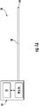
- the detection system 20 includes a single fiber optic cable 28 with at least one fiber optic core.
- the term fiber optic cable 28 includes any form of optical fiber.
- an optical fiber is a length of cable that is composed of one or more optical fiber cores of single-mode, multimode, polarization maintaining, photonic crystal fiber or hollow core.
- a node 34 is located at the termination point of a fiber optic cable 32 and is inherently included in the definition of a fiber optic cable 28. The node 34 is positioned in communication with the ambient atmosphere.
- a light source 36 such as a laser diode for example, and a light sensitive device 38, such as a photodiode for example, are coupled to the fiber optic cable 28.
- a control system 50 of the detection system 20, discussed in further detail below, is utilized to manage the detection system operation and may include control of components, data acquisition, data processing and data analysis.
- the light from the light source is transmitted through the node 34 to the surrounding area, illustrated schematically at 21.
- the light 21 interacts with one or more particles indicative of a condition, illustrated schematically at 22, and is reflected or transmitted back to the node 34, illustrated schematically at 23.
- a comparison of the light provided to the node 34 and/or changes to the light reflected back to the light sensitive device 38 from the node 34 will indicate whether or not changes in the atmosphere are present in the ambient atmosphere adjacent the node 34 that are causing the scattering of the light.
- the scattered light as described herein is intended to additionally include reflected, transmitted, and absorbed light.
- the detection system 20 can include a plurality of nodes 34.
- a plurality of fiber optic cables 28 and corresponding nodes 34 are each associated with a distinct light sensitive device 38.
- the signal output from each node 34 can be monitored.
- a predetermined event or condition it will be possible to localize the position of the event because the position of each node 34 within the system 20 is known.
- a plurality of fiber optic cables 28 may be coupled to a single light sensitive device.
- the control system 50 is able to localize the scattered light, i.e. identify the scattered light received from each of the plurality of nodes 34.
- the control system 50 uses the position of each node 34, specifically the length of the fiber optic cables 28 associated with each node 34 and the corresponding time of flight (i.e. the time elapsed between when the light was emitted by the light source 36 and when the light was received by the light sensitive device 38), to associate different parts of the light signal with each of the respective nodes 34 that are connected to that light sensitive device 38.
- the time of flight may include the time elapsed between when the light is emitted from the node and when the scattered light is received back at the node. In such embodiments, the time of flight provides information regarding the distance of the object relative to the node.
- two substantially identical and parallel light transmission fiber cores 40, 42 are included in the fiber optic cable 28 and terminate at the node 34.
- the light source 36 may be coupled to the first fiber core 40 and the light sensitive device 38 may be coupled to the second fiber core 42, for example near a first end of the fiber optic cable 28.
- the light source 36 is selectively operable to emit light, which travels down the first fiber core 40 of the fiber optic cable 28 to the node 34. At the node 34, the emitted light is expelled into the adjacent atmosphere. The light is scattered and transmitted back into the node 34 and down the fiber cable 28 to the light sensitive device 38 via the second fiber core 42.
- the detection system 20 includes a fiber harness 30 having a plurality of fiber optic cables 28 bundled together.
- a fiber harness 30 can also be only a single fiber optic cable 28.
- a plurality of fiber cores 40, 42 are bundled together at a location to form a fiber harness backbone 31 with the ends of the fiber optic cables 28 being separated (not included in the bundled backbone) to define a plurality of fiber optic branches 32 of the fiber harness 30.
- the plurality of fiber cores 40, 42 branch off to form a plurality of individual fiber branches 32, each of which terminates at a node 34.
- the fiber harness 30 additionally includes an emitter leg 33 and a receiver leg 35 associated with the fiber branches 32.
- the emitter leg 33 may contain the first fiber cores 40 from each of the plurality of fiber branches 32 and the receiver leg 35 may contain all of the second fiber cores 42 from each of the fiber branches 32.
- the length of the fiber optic cores 40, 42 extending between the emitter leg 33 or the receiver leg 35 and the node 34 may vary in length such that the branches 32 and corresponding nodes 34 are arranged at various positions along the length of the fiber harness backbone 31. In an embodiment, the positions of the nodes 34 may be set during manufacture, or at the time of installation of the system 20.
- the fiber harness 30 may include a fiber optic cable (not shown) having a plurality of branches 32 integrally formed therewith and extending therefrom.
- the branches 32 may include only a single fiber optic core.
- the configuration, specifically the spacing of the nodes 34 within a fiber harness 30 may be substantially equidistant, or may vary over the length of the harness 30. In an embodiment, the positioning of each node 34 may correlate to a specific location within the designated area.
- the system 20 includes a light mold, guide, or other distribution device 39, as shown in FIG. 12 .
- the light mold 39 is positioned such that the node is arranged in communication with the light mold which is coupled to the ambient atmosphere.
- the light mold 39 directs the light to a first position and illuminates the atmosphere at a given angle ⁇ and receives light from the atmosphere at a given angular position.
- the resultant light scattering that occurs is not uniform about the periphery of the emitted light. Rather, the scattering that occurs is also angularly dependent which causes the light to scatter more intensely in some directions relative to the emitted light versus other directions.
- the system 20 needs to be able to discriminate between the back scatter from the light emitted at a known angular position and the light scatter from another angular position.
- the light mold 39 is utilized to collect light from multiple angles.
- the light mold 39 is a node 34 where the signal of reflected light from a node 34 is collected and is evaluated based on a time of flight delay. The time of flight provides additional information regarding the distance between the back scatter position and a secondary angular position.
- the light mold 39 is a component of the detection system that enables collection of light from multiple angles.
- the light mold 39 can be fabricated from any suitable material, including but not limited to, fiber optics, free space optics, molded plastic optics or photonic integrated circuits for example.
- the light mold 39 and node 34 may be integrated; a plurality of fiber optic cores 40 can be bundled together in a fiber branch 32, such that a node 34 contains a plurality of fiber optic cores placed at different angles with respect to the emitted light.
- the detection system 20 may additionally include a plurality of fiber harnesses 30.
- a distinct light sensitive device 38 is associated with each of the plurality of fiber harnesses 30.
- a single light source 36 may be operably coupled to the plurality of light transmission fiber cores 40 within the plurality of fiber harnesses 30 of the system 20.
- the detection system 20 may include a plurality of light sources 36, each of which is coupled to one or more of the plurality of fiber harnesses 30.
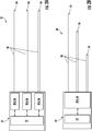
- the detection system 20 may be configured to monitor a predetermined area such as a building.
- the detection system 20 may be especially utilized for predetermined areas having a crowded environment, such as a server room, as shown in FIG. 6 for example.
- Each fiber harness 30 may be aligned with one or more rows of equipment 46, and each node 34 therein may be located directly adjacent to one of the towers 48 within the rows 46.
- nodes may be arranged so as to monitor specific enclosures, electronic devices, or machinery. Positioning of the nodes 34 in such a manner allows for earlier detection of a condition as well as localization, which may limit the exposure of the other equipment in the room to the same condition.
- the detection system 20 may be integrated into an aircraft, such as for monitoring a cargo bay, avionics rack, lavatory, or another confined region of the aircraft that may be susceptible to fires or other events.
- the control system 50 of the detection system 20 is utilized to manage the detection system operation and may include control of components, data acquisition, data processing and data analysis.
- the control system 50 illustrated in FIG. 7 , includes at least one light sensitive device 38, at least one light source, 36, and a control unit 52, such as a computer having one or more processors 54 and memory 56 for implementing an algorithm 58 as executable instructions that are executed by the processor 54.
- the instructions may be stored or organized in any manner at any level of abstraction.
- the processor 54 may be any type of processor, including a central processing unit (“CPU”), a general purpose processor, a digital signal processor, a microcontroller, an application specific integrated circuit (“ASIC”), a field programmable gate array (“FPGA”), or the like.
- memory 56 may include random access memory (“RAM”), read only memory (“ROM”), or other electronic, optical, magnetic, or any other computer readable medium for storing and supporting processing in the memory 56 .
- the control unit 52 may be associated with one or more input/output devices 60.
- the input/output devices 60 may include an alarm or other signal, or a fire suppression system which are activated upon detection of a predefined event or condition. It should be understood herein that the term alarm, as used herein, may indicate any of the possible outcomes of a detection.
- the processor 54 may be coupled to the at least one light source 36 and the at least one light sensitive device 38 via connectors.
- the light sensitive device 38 is configured to convert the scattered light received from a node 34 into a corresponding signal receivable by the processor 54.
- the signal generated by the light sensing device 38 is an electronic signal.
- the signal output from the light sensing device 38 is then provided to the control unit 52 for processing using an algorithm to determine whether a predefined condition is present.
- the signal received by or outputted from the light sensitive device(s) 38 may be amplified and/or filtered, such as by a comparator (not shown), to reduce or eliminate irrelevant information within the signal prior to being communicated to the control unit 52 located remotely from the node 34.
- the amplification and filtering of the signal may occur directly within the light sensing device 38, or alternatively, may occur via one or more components disposed between the light sensing device 38 and the control unit 52.
- the control unit 52 may control the data acquisition of the light sensitive device 38, such as by adjusting the gain of the amplifier, the bandwidth of filters, sampling rates, the amount of timing and data buffering for example.
- the light sensitive device 38 may include one or more Avalanche Photodiode (APD) sensors 64.
- APD Avalanche Photodiode
- an array 66 of APD sensors 64 may be associated with the one or more fiber harnesses 30.
- the number of APD sensors 64 within the sensor array 66 is equal to or greater than the total number of fiber harnesses 30 operably coupled thereto.
- embodiments where the total number of APD sensors 64 within the sensor array 66 is less than the total number of fiber harnesses 30 are also contemplated herein.
- Data representative of the output from each APD sensor 64 in the APD array 66 is periodically taken by a switch 68, or alternatively, is collected simultaneously.
- the data acquisition 67 collects the electronic signals from the APD and associates the collected signals with metadata.
- the metadata as an example can be time, frequency, location or node.
- the electronic signals are from the APD are synchronized to the laser modulation such that the electrical signals are collected for a period of time that starts when the laser is pulsed to several microseconds after the laser pulse.
- the data will be collected and processed by the processor 54 to determine whether any of the nodes 34 indicates the existence of a predefined condition or event.
- the switch 68 is therefore configured to collect information from the various APD sensors 64 of the sensor array 66 sequentially. While the data collected from a first APD sensor 64 is being processed to determine if an event or condition has occurred, the data from a second APD 66 of the sensor array 66 is collected and provided to the processor 54 for analysis. When a predefined condition or event has been detected from the data collected from one of the APD sensors 64, the switch 68 may be configured to provide additional information from the same APD sensor 64 to the processor 54 to track the condition or event.
- a method of operation 100 of the detection system 20 is illustrated in FIG. 9 .
- the control unit 52 operably coupled to the light source 36 is configured to selectively energize the light source 36, as shown in block 102, and to emit light to a fiber harness 30 coupled thereto as shown in block 104. Based on the desired operation of the detection system 20, the control unit 52 may vary the intensity, duration, repetition, frequency, or other properties, of the light emitted. As the light travels down the first fiber core 40 of the at least one fiber optic branch 32, all or a portion of the light is emitted at one or more nodes 34 of the fiber harness 30. In block 106, light is scattered in the predetermined area and transmitted back through the fiber optic branches 32 via the second fiber cores 42.
- the scattered light may include one or more of scattered light within the atmosphere adjacent the node and scattered light that reflects from an interior of the fiber optic branch 32.
- the scattered light is transmitted to the at least one light sensing device 38 in block 108.
- the light sensing device 38 generates a signal in response to the scattered light received by each node 34, and provides that signal to the control unit 52 for further processing.
- each of the signals representing the scattered light received by the corresponding nodes 34 are evaluated to determine whether the light at the node 34 is indicative of a predefined condition, such as smoke for example.
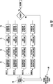
- a schematic diagram illustrating an example of a flow path for processing the signals generated by each of the nodes 34 is illustrated.
- the signal indicative of scattered light 69 is parsed, shown at block 70, into a plurality of signals based on their respective originating node 34.
- background signals illustrated schematically at 72, are subtracted from the data before the pulse features are evaluated for each of the individual signals.
- one or more characteristics or features (pulse features) of the signal may be determined.
- characteristics or features include, but are not limited to, a peak height, an area under a curve defined by the signal, statistical characteristics such as mean, variance, and/or higher-order moments, correlations in time, frequency, space, and/or combinations thereof, and empirical features as determined by deep learning, dictionary learning, and/or adaptive learning and the like.
- the time of flight record is parsed and features are extracted.
- the time of flight record can cover a period of time.
- a time of flight record can record light intensity over 0.001 -1,000,000 nanoseconds, 0.1-100,000 nanoseconds, or 0.1-10,000 microseconds.
- the features extracted from the signal can include, but are not limited to height, full width at half maximum, signal pick up time, signal drop off time, group velocity, integration, rate of change, mean, and variance for example.
- the features may then be further processed by using, for example, smoothing, Fourier transforms or cross correlation.
- the processed data is then sent to the detection algorithm at block 78 to determine whether or not the signal indicates the presence and/or magnitude of a condition or event at a corresponding node 34.
- This evaluation may be a simple binary comparison that does not identify the magnitude of deviation between the characteristic and a threshold.
- the evaluation may also be a comparison of a numerical function of the characteristic or characteristics to a threshold.
- the threshold may be determined a priori or may be determined from the signal.
- the determination of the threshold from the signal may be called background learning. Background learning may be accomplished by adaptive filtering, model-based parameter estimation, statistical modeling, and the like.
- the remainder of the detection algorithm is not applied in order to reduce the total amount processing done during the detection algorithm.
- an alarm or other fire suppression system may, but need not be activated. It should be understood that the process for evaluating the data illustrated and described herein is intended as an example only and that other processes including some or all of the steps indicated in the FIG. are also contemplated herein.
- the evaluation may also advantageously employ classifiers including those that may be learned from the signal via deep learning techniques including, but not limited to deep neural networks, convolutional neural networks, recursive neural networks, dictionary learning, bag of visual/depth word techniques, Support Vector Machine (SVM), Decision Trees, Decision Forests, Fuzzy Logic, and the like.
- the classifiers may also be constructed using Markov Model techniques, Hidden Markov Models (HMM), Markov Decision Processes (MDP), Partially Observable MDPs, Markov Decision Logic, Probabilistic Programming, and the like.
- the processor 54 may additionally be configured to evaluate the plurality of signals or characteristics thereof collectively, such as through a data fusion operation to produce fused signals or fused characteristics.
- the data fusion operation may provide information related to time and spatial evolution of an event or predetermined condition.
- a data fusion operation may be useful in detecting a lower level event, insufficient to initiate an alarm at any of the nodes 34 individually. For example, in the event of a slow burning fire, the light signal generated by a small amount of smoke near each of the nodes 34 individually may not be sufficient to initiate an alarm.
- the increase in light returned to the light sensitive device 38 from multiple nodes 34 may indicate the occurrence of an event or the presence of an object not otherwise detected.
- the fusion is performed by Bayesian Estimation.
- linear or non-linear joint estimation techniques may be employed such as maximum likelihood (ML), maximum a priori (MAP), non-linear least squares (NNLS), clustering techniques, support vector machines, decision trees and forests, and the like.
- the processor 54 is configured to analyze the signals generated by at least one light sensing device 38 relative to time.
- the detection algorithm may be configured to apply one or more of a Fourier transform, Wavelet transform, space-time transform, Choi-Williams distribution, Wigner-Ville distribution and the like, to the signals to convert the signals from a temporal domain to a frequency domain. This transformation may be applied to the signals when the nodes 34 are being analyzed individually, when the nodes 34 are being analyzed collectively during a data fusion, or both.
- the relationship between the light scattering and the magnitude or presence of a condition is inferred by measuring a signal's causality and dependency.
- the measure of a causality utilizes one or more signal features as an input and determines one or more outputs from a calculation of a hypothesis testing method, foreground ratio, second derivative, mean or Granger Causality Test.
- one or more signal features may be used as an input to evaluate the dependency of a signal.
- One or more outputs are selected from a calculation of a correlation, fast Fourier transform coefficients, a second derivative, or a window. The magnitude and presence of the condition is then based on the causality and dependency.
- the magnitude and presence of a condition may be calculated utilizing one or more evaluation approaches: a threshold, velocity, rate of change or a classifier.
- the detection algorithm may include utilizing the output from the calculation causality, dependency or both. This is used to indicate the presence of the condition at one or more nodes 34 and initiate a response.
- the detection algorithm may be configured to evaluate the signals in a fixed time window to determine the magnitude of the frequency or the strength of the motion of the smoke. Accordingly, if the magnitude of a frequency component exceeds a predetermined threshold, the detection algorithm may initiate an alarm indicating the presence of a fire.
- the predetermined threshold is about 10 Hz such that when the magnitude of the optical smoke frequency exceeds the threshold, smoke is present.
- the algorithm 58 is configured to distinguish between different events or conditions based on the rate of change in the light scattered by the atmosphere near the node 34 and received by one or more of the nodes 34 over time.
- FIGS. 11A and 11B graphs of the signals recorded from a node 34 over time with respect to different events are illustrated.
- FIG. 11A indicates the change in the light signal received by a node 34 as a person walks through the area being monitored by the node 34. As shown in the graph, the movement of a person appears as steps having varying magnitudes.
- FIG. 11A indicates the change in the light signal received by a node 34 as a person walks through the area being monitored by the node 34. As shown in the graph, the movement of a person appears as steps having varying magnitudes.
- FIG. 11A indicates the change in the light signal received by a node 34 as a person walks through the area being monitored by the node 34. As shown in the graph, the movement of a person appears as steps having varying magnitudes.
- each predefined event detectable by the detection system 20 may have one or more unique parameters associated therewith.
- the light emitting device 36 may be modulated such that the device 36 is selectively operated to generate modulated light in a specific pattern.
- the light within the pattern may vary in intensity, width, frequency, phase, and may comprise discrete pulses or may be continuous.
- the specific pattern of light may be designed to have desirable properties such as a specific autocorrelation with itself or cross-correlation with a second specific pattern. When the light is emitted in a specific pattern, the light scattered back to a corresponding light sensing device 38 should arrive in the substantially same pattern.
- Use of one or more specific and known patterns provides enhanced processing capabilities by allowing for the system 20 to reduce overall noise.
- This reduction in noise when combined with the signal processing may result in an improved signal to noise ratio and the total number of false events or conditions detected will decrease.
- the device sensitivity may be improved thereby increasing the limits of the detection system 20.
- cross-correlating one or more second patterns specific causes of transmitted or reflected signals may be distinguished, e.g. by Bayesian estimation of the respective cross-correlations of the received signal with the one or more second patterns.
- modulation of the light signal emitted by the light source 36 may provide improved detection by determining more information about the event or condition causing the scatter in the light signal received by the node 34. For example, such modulation may allow the system 20 to more easily distinguish between a person walking through the designated area adjacent a node, as shown in FIG. 11A , and a smoldering fire adjacent the node 34.
- each node 34 includes an emitting core 40 for transmitting light to the ambient area outside the fiber harness 30 adjacent the node 34, and a plurality of receiving cores 42, 44 for collecting/receiving scattered light from the designated area being monitored by the node 34.
- each receiving core 42, 44 is operably connected to a different light sensitive device 38 in order to differentiate between the scattered light received by the different cores.
- the receiving cores 42, 44 are different lengths and can be operably connected to the same light sensitive device and the scattered light received by each of the light sensitive devices 38 can be differentiated based on the time of flight of the scattered light.
- a fiber optic cable 28 in FIG. 12 is illustrated as having a second core 42 and a third core 44 for transmitting scattered light back to a light sensitive device 38, embodiments having three or more cores for receiving the scattered light are also contemplated herein.
- embodiments where there is a plurality of emitting cores are contemplated herein.
- embodiments where the at least one emitting core also receives scattered light are also contemplated herein.
- Each of the plurality of cores 42, 44 configured to receive scattered light back to a light sensitive device 38 is oriented at a different angle relative to the emitting core 40.
- a first angle is formed between the emitting core 40 and the first receiving core 42
- a second angle is formed between the emitting core 40 and the second receiving core 44.
- the first angle and the second angle are known and are distinct.
- the different angles can be achieved by physically orienting/positioning the cores differently.
- the different angles can be achieved by using a plurality of nodes 34, wherein not all of the nodes include an emitting core 40.
- a light mold 39 can be used to receive scattered light from different scattering angles at the plurality of receiving cores 42, 44.
- the light mold 39 is operably connected to a node 34 and is configured to support the emitting core 40 and the plurality of receiving cores 42, 44 such that the plurality of cores 40, 42, 44 at the node 34 each receive scattered light from a desired angle.
- the algorithm 58 executed by the processor 54 is configured to provide the two signals associated with each node 34 into an algorithm.
- the processor 54 is configured to use the known angles and the algorithm to distinguish between various types of conditions, such as gas, dust, water vapor, solid objects and smoke.
Applications Claiming Priority (1)
| Application Number | Priority Date | Filing Date | Title |
|---|---|---|---|
| US201662420828P | 2016-11-11 | 2016-11-11 |
Publications (2)
| Publication Number | Publication Date |
|---|---|
| EP3321906A1 true EP3321906A1 (de) | 2018-05-16 |
| EP3321906B1 EP3321906B1 (de) | 2019-10-02 |
Family
ID=60301885
Family Applications (1)
| Application Number | Title | Priority Date | Filing Date |
|---|---|---|---|
| EP17201027.4A Active EP3321906B1 (de) | 2016-11-11 | 2017-11-10 | Auf hochempfindlicher faseroptik basierende detektion |
Country Status (3)
| Country | Link |
|---|---|
| US (1) | US20180136122A1 (de) |
| EP (1) | EP3321906B1 (de) |
| CN (1) | CN108072596A (de) |
Cited By (1)
| Publication number | Priority date | Publication date | Assignee | Title |
|---|---|---|---|---|
| WO2020263549A1 (en) * | 2019-06-27 | 2020-12-30 | Carrier Corporation | Spatial and temporal pattern analysis for integrated smoke detection and localization |
Families Citing this family (7)
| Publication number | Priority date | Publication date | Assignee | Title |
|---|---|---|---|---|
| US20190236922A1 (en) * | 2018-01-30 | 2019-08-01 | The Boeing Company | Optical Cabin and Cargo Smoke Detection Using Multiple Spectrum Light |
| US11361643B2 (en) | 2018-07-13 | 2022-06-14 | Carrier Corporation | High sensitivity fiber optic based detection system |
| WO2020010596A1 (en) * | 2018-07-13 | 2020-01-16 | Carrier Corporation | High sensitivity fiber optic based detection system |
| CN109559059B (zh) * | 2018-12-17 | 2022-12-27 | 重庆邮电大学 | 一种基于回归决策树的光纤生产规则制定方法 |
| US10845294B1 (en) | 2019-07-03 | 2020-11-24 | Raytheon Technologies Corporation | Systems and methods for particulate ingestion sensing in gas turbine engines |
| US11492967B2 (en) | 2019-07-03 | 2022-11-08 | Raytheon Technologies Corporation | Particulate ingestion sensor for gas turbine engines |
| US20220397525A1 (en) * | 2021-06-09 | 2022-12-15 | Carrier Corporation | Apparatus and method for verifying optical functionality in a chamberless smoke detector |
Citations (3)
| Publication number | Priority date | Publication date | Assignee | Title |
|---|---|---|---|---|
| EP1408469A2 (de) * | 2002-10-07 | 2004-04-14 | Novar GmbH | Branderkennungsverfahren und Brandmelder zu dessen Durchführung |
| EP1887536A1 (de) * | 2006-08-09 | 2008-02-13 | Siemens Schweiz AG | Streulicht-Rauchmelder |
| DE102013213721A1 (de) * | 2013-03-07 | 2014-05-08 | Siemens Aktiengesellschaft | Optisches Raucherfassungsmodul, Brandmeldeanlage sowie Verwendung eines optischen Raucherfassungsmoduls in einem Nuklearbereich oder EX-Bereich |
Family Cites Families (20)
| Publication number | Priority date | Publication date | Assignee | Title |
|---|---|---|---|---|
| JPS5683895U (de) * | 1979-12-01 | 1981-07-06 | ||
| SU1179402A1 (ru) * | 1984-03-11 | 1985-09-15 | Предприятие П/Я А-3462 | Датчик дыма |
| US4764671A (en) * | 1986-10-03 | 1988-08-16 | Kollmorgen Corporation | Fiber optic fluid sensor using coated sensor tip |
| US4839527A (en) * | 1986-10-28 | 1989-06-13 | Alan Leitch | Optical-fibre smoke detection/analysis system |
| US4870394A (en) * | 1988-01-29 | 1989-09-26 | Systron-Donner Corp. | Smoke detector with improved testing |
| GB2274333B (en) * | 1993-01-07 | 1996-12-11 | Hochiki Co | Smoke detecting apparatus capable of detecting both smoke and fine particles |
| DE19902319B4 (de) * | 1999-01-21 | 2011-06-30 | Novar GmbH, Albstadt-Ebingen Zweigniederlassung Neuss, 41469 | Streulichtbrandmelder |
| GB0303155D0 (en) * | 2003-02-12 | 2003-03-19 | Sensornet Ltd | Distributed sensor |
| JP4535697B2 (ja) * | 2003-07-23 | 2010-09-01 | オリンパス株式会社 | 生体組織の光散乱観測内視鏡装置 |
| US6905258B2 (en) * | 2003-08-27 | 2005-06-14 | Mitutoyo Corporation | Miniature imaging encoder readhead using fiber optic receiver channels |
| US7233253B2 (en) * | 2003-09-12 | 2007-06-19 | Simplexgrinnell Lp | Multiwavelength smoke detector using white light LED |
| US7301641B1 (en) * | 2004-04-16 | 2007-11-27 | United States Of America As Represented By The Secretary Of The Navy | Fiber optic smoke detector |
| GB2430027A (en) * | 2005-09-09 | 2007-03-14 | Kidde Ip Holdings Ltd | Fibre bragg temperature sensors |
| GB0919906D0 (en) * | 2009-11-13 | 2009-12-30 | Qinetiq Ltd | Improvements to distributed fibre optic sensing |
| CN102033036B (zh) * | 2010-10-20 | 2013-11-27 | 上海理工大学 | 光全散射式在线粒度测量装置的测量方法 |
| CN102622847B (zh) * | 2012-03-23 | 2014-06-11 | 武汉发博科技有限公司 | 反射式点型光纤感烟火灾探测器 |
| CN102636418A (zh) * | 2012-03-26 | 2012-08-15 | 哈尔滨工程大学 | 一种多光谱后向散射式烟尘粒径及浓度测量装置及其测量方法 |
| CN104266945B (zh) * | 2014-10-18 | 2017-01-18 | 山东理工大学 | 动态光散射颗粒检测装置的检测方法 |
| CN204313854U (zh) * | 2014-12-25 | 2015-05-06 | 深圳市博亿精科科技有限公司 | 一种聚焦型光纤传感器 |
| CN104833624A (zh) * | 2015-05-20 | 2015-08-12 | 浙江科技学院 | 一种基于光纤的浊度测量方法及装置 |
-
2017
- 2017-11-10 EP EP17201027.4A patent/EP3321906B1/de active Active
- 2017-11-10 CN CN201711111390.XA patent/CN108072596A/zh active Pending
- 2017-11-10 US US15/809,654 patent/US20180136122A1/en not_active Abandoned
Patent Citations (3)
| Publication number | Priority date | Publication date | Assignee | Title |
|---|---|---|---|---|
| EP1408469A2 (de) * | 2002-10-07 | 2004-04-14 | Novar GmbH | Branderkennungsverfahren und Brandmelder zu dessen Durchführung |
| EP1887536A1 (de) * | 2006-08-09 | 2008-02-13 | Siemens Schweiz AG | Streulicht-Rauchmelder |
| DE102013213721A1 (de) * | 2013-03-07 | 2014-05-08 | Siemens Aktiengesellschaft | Optisches Raucherfassungsmodul, Brandmeldeanlage sowie Verwendung eines optischen Raucherfassungsmoduls in einem Nuklearbereich oder EX-Bereich |
Cited By (4)
| Publication number | Priority date | Publication date | Assignee | Title |
|---|---|---|---|---|
| WO2020263549A1 (en) * | 2019-06-27 | 2020-12-30 | Carrier Corporation | Spatial and temporal pattern analysis for integrated smoke detection and localization |
| GB2592463A (en) * | 2019-06-27 | 2021-09-01 | Carrier Corp | Spatial and temporal pattern analysis for integrated smoke detection and localization |
| US11594116B2 (en) | 2019-06-27 | 2023-02-28 | Carrier Corporation | Spatial and temporal pattern analysis for integrated smoke detection and localization |
| GB2592463B (en) * | 2019-06-27 | 2023-05-17 | Carrier Corp | Spatial and temporal pattern analysis for integrated smoke detection and localization |
Also Published As
| Publication number | Publication date |
|---|---|
| CN108072596A (zh) | 2018-05-25 |
| US20180136122A1 (en) | 2018-05-17 |
| EP3321906B1 (de) | 2019-10-02 |
Similar Documents
| Publication | Publication Date | Title |
|---|---|---|
| EP3321906B1 (de) | Auf hochempfindlicher faseroptik basierende detektion | |
| US10852202B2 (en) | High sensitivity fiber optic based detection | |
| CN109964259B (zh) | 基于高灵敏度光纤的检测 | |
| EP3321908A1 (de) | Auf faseroptik basierte überwachung von temperatur- und/oder rauchbedingungen an elektronischen bauteilen | |
| US11067457B2 (en) | Fiber optic based smoke and/or overheat detection and monitoring for aircraft | |
| CN109983515B (zh) | 基于高灵敏度光纤的检测系统及其操作方法 | |
| EP3321907B1 (de) | Faseroptikbasierter rauch- und/oder überhitzungsschutz und -überwachung für flugzeuge | |
| EP4300457A2 (de) | Hochempfindliche glasfaserbasierte detektion | |
| US11361643B2 (en) | High sensitivity fiber optic based detection system | |
| US20190287366A1 (en) | High sensitivity fiber optic based detection | |
| EP3539102A1 (de) | Auf hochempfindlicher faseroptik basierende detektion | |
| US20210201645A1 (en) | Chambered high sensitivity fiber optic smoke detection | |
| EP3538872B1 (de) | Verfahren zur faseroptik-basierten messung eines zustands | |
| EP3539107B1 (de) | Auf hochempfindlicher faseroptik basierende detektion | |
| US11448581B2 (en) | High sensitivity fiber optic based detection system | |
| WO2020010599A1 (en) | High sensitivity fiber optic based detection | |
| EP3821416A2 (de) | Auf hochempfindlicher faseroptik basierendes detektionssystem | |
| EP3821414A1 (de) | Auf hochempfindlicher faseroptik basierende detektion |
Legal Events
| Date | Code | Title | Description |
|---|---|---|---|
| PUAI | Public reference made under article 153(3) epc to a published international application that has entered the european phase |
Free format text: ORIGINAL CODE: 0009012 |
|
| STAA | Information on the status of an ep patent application or granted ep patent |
Free format text: STATUS: THE APPLICATION HAS BEEN PUBLISHED |
|
| AK | Designated contracting states |
Kind code of ref document: A1 Designated state(s): AL AT BE BG CH CY CZ DE DK EE ES FI FR GB GR HR HU IE IS IT LI LT LU LV MC MK MT NL NO PL PT RO RS SE SI SK SM TR |
|
| AX | Request for extension of the european patent |
Extension state: BA ME |
|
| STAA | Information on the status of an ep patent application or granted ep patent |
Free format text: STATUS: REQUEST FOR EXAMINATION WAS MADE |
|
| 17P | Request for examination filed |
Effective date: 20181116 |
|
| RBV | Designated contracting states (corrected) |
Designated state(s): AL AT BE BG CH CY CZ DE DK EE ES FI FR GB GR HR HU IE IS IT LI LT LU LV MC MK MT NL NO PL PT RO RS SE SI SK SM TR |
|
| GRAP | Despatch of communication of intention to grant a patent |
Free format text: ORIGINAL CODE: EPIDOSNIGR1 |
|
| STAA | Information on the status of an ep patent application or granted ep patent |
Free format text: STATUS: GRANT OF PATENT IS INTENDED |
|
| INTG | Intention to grant announced |
Effective date: 20190411 |
|
| GRAS | Grant fee paid |
Free format text: ORIGINAL CODE: EPIDOSNIGR3 |
|
| GRAA | (expected) grant |
Free format text: ORIGINAL CODE: 0009210 |
|
| STAA | Information on the status of an ep patent application or granted ep patent |
Free format text: STATUS: THE PATENT HAS BEEN GRANTED |
|
| AK | Designated contracting states |
Kind code of ref document: B1 Designated state(s): AL AT BE BG CH CY CZ DE DK EE ES FI FR GB GR HR HU IE IS IT LI LT LU LV MC MK MT NL NO PL PT RO RS SE SI SK SM TR |
|
| REG | Reference to a national code |
Ref country code: GB Ref legal event code: FG4D |
|
| REG | Reference to a national code |
Ref country code: CH Ref legal event code: EP Ref country code: AT Ref legal event code: REF Ref document number: 1187036 Country of ref document: AT Kind code of ref document: T Effective date: 20191015 |
|
| REG | Reference to a national code |
Ref country code: DE Ref legal event code: R096 Ref document number: 602017007457 Country of ref document: DE |
|
| REG | Reference to a national code |
Ref country code: IE Ref legal event code: FG4D |
|
| REG | Reference to a national code |
Ref country code: NL Ref legal event code: MP Effective date: 20191002 |
|
| REG | Reference to a national code |
Ref country code: LT Ref legal event code: MG4D |
|
| REG | Reference to a national code |
Ref country code: AT Ref legal event code: MK05 Ref document number: 1187036 Country of ref document: AT Kind code of ref document: T Effective date: 20191002 |
|
| PG25 | Lapsed in a contracting state [announced via postgrant information from national office to epo] |
Ref country code: BG Free format text: LAPSE BECAUSE OF FAILURE TO SUBMIT A TRANSLATION OF THE DESCRIPTION OR TO PAY THE FEE WITHIN THE PRESCRIBED TIME-LIMIT Effective date: 20200102 Ref country code: FI Free format text: LAPSE BECAUSE OF FAILURE TO SUBMIT A TRANSLATION OF THE DESCRIPTION OR TO PAY THE FEE WITHIN THE PRESCRIBED TIME-LIMIT Effective date: 20191002 Ref country code: PT Free format text: LAPSE BECAUSE OF FAILURE TO SUBMIT A TRANSLATION OF THE DESCRIPTION OR TO PAY THE FEE WITHIN THE PRESCRIBED TIME-LIMIT Effective date: 20200203 Ref country code: AT Free format text: LAPSE BECAUSE OF FAILURE TO SUBMIT A TRANSLATION OF THE DESCRIPTION OR TO PAY THE FEE WITHIN THE PRESCRIBED TIME-LIMIT Effective date: 20191002 Ref country code: LV Free format text: LAPSE BECAUSE OF FAILURE TO SUBMIT A TRANSLATION OF THE DESCRIPTION OR TO PAY THE FEE WITHIN THE PRESCRIBED TIME-LIMIT Effective date: 20191002 Ref country code: SE Free format text: LAPSE BECAUSE OF FAILURE TO SUBMIT A TRANSLATION OF THE DESCRIPTION OR TO PAY THE FEE WITHIN THE PRESCRIBED TIME-LIMIT Effective date: 20191002 Ref country code: NL Free format text: LAPSE BECAUSE OF FAILURE TO SUBMIT A TRANSLATION OF THE DESCRIPTION OR TO PAY THE FEE WITHIN THE PRESCRIBED TIME-LIMIT Effective date: 20191002 Ref country code: ES Free format text: LAPSE BECAUSE OF FAILURE TO SUBMIT A TRANSLATION OF THE DESCRIPTION OR TO PAY THE FEE WITHIN THE PRESCRIBED TIME-LIMIT Effective date: 20191002 Ref country code: LT Free format text: LAPSE BECAUSE OF FAILURE TO SUBMIT A TRANSLATION OF THE DESCRIPTION OR TO PAY THE FEE WITHIN THE PRESCRIBED TIME-LIMIT Effective date: 20191002 Ref country code: GR Free format text: LAPSE BECAUSE OF FAILURE TO SUBMIT A TRANSLATION OF THE DESCRIPTION OR TO PAY THE FEE WITHIN THE PRESCRIBED TIME-LIMIT Effective date: 20200103 Ref country code: PL Free format text: LAPSE BECAUSE OF FAILURE TO SUBMIT A TRANSLATION OF THE DESCRIPTION OR TO PAY THE FEE WITHIN THE PRESCRIBED TIME-LIMIT Effective date: 20191002 Ref country code: NO Free format text: LAPSE BECAUSE OF FAILURE TO SUBMIT A TRANSLATION OF THE DESCRIPTION OR TO PAY THE FEE WITHIN THE PRESCRIBED TIME-LIMIT Effective date: 20200102 |
|
| PG25 | Lapsed in a contracting state [announced via postgrant information from national office to epo] |
Ref country code: CZ Free format text: LAPSE BECAUSE OF FAILURE TO SUBMIT A TRANSLATION OF THE DESCRIPTION OR TO PAY THE FEE WITHIN THE PRESCRIBED TIME-LIMIT Effective date: 20191002 Ref country code: RS Free format text: LAPSE BECAUSE OF FAILURE TO SUBMIT A TRANSLATION OF THE DESCRIPTION OR TO PAY THE FEE WITHIN THE PRESCRIBED TIME-LIMIT Effective date: 20191002 Ref country code: HR Free format text: LAPSE BECAUSE OF FAILURE TO SUBMIT A TRANSLATION OF THE DESCRIPTION OR TO PAY THE FEE WITHIN THE PRESCRIBED TIME-LIMIT Effective date: 20191002 Ref country code: IS Free format text: LAPSE BECAUSE OF FAILURE TO SUBMIT A TRANSLATION OF THE DESCRIPTION OR TO PAY THE FEE WITHIN THE PRESCRIBED TIME-LIMIT Effective date: 20200224 |
|
| PG25 | Lapsed in a contracting state [announced via postgrant information from national office to epo] |
Ref country code: AL Free format text: LAPSE BECAUSE OF FAILURE TO SUBMIT A TRANSLATION OF THE DESCRIPTION OR TO PAY THE FEE WITHIN THE PRESCRIBED TIME-LIMIT Effective date: 20191002 |
|
| REG | Reference to a national code |
Ref country code: DE Ref legal event code: R097 Ref document number: 602017007457 Country of ref document: DE |
|
| PG2D | Information on lapse in contracting state deleted |
Ref country code: IS |
|
| PG25 | Lapsed in a contracting state [announced via postgrant information from national office to epo] |
Ref country code: DK Free format text: LAPSE BECAUSE OF FAILURE TO SUBMIT A TRANSLATION OF THE DESCRIPTION OR TO PAY THE FEE WITHIN THE PRESCRIBED TIME-LIMIT Effective date: 20191002 Ref country code: LU Free format text: LAPSE BECAUSE OF NON-PAYMENT OF DUE FEES Effective date: 20191110 Ref country code: MC Free format text: LAPSE BECAUSE OF FAILURE TO SUBMIT A TRANSLATION OF THE DESCRIPTION OR TO PAY THE FEE WITHIN THE PRESCRIBED TIME-LIMIT Effective date: 20191002 Ref country code: RO Free format text: LAPSE BECAUSE OF FAILURE TO SUBMIT A TRANSLATION OF THE DESCRIPTION OR TO PAY THE FEE WITHIN THE PRESCRIBED TIME-LIMIT Effective date: 20191002 Ref country code: EE Free format text: LAPSE BECAUSE OF FAILURE TO SUBMIT A TRANSLATION OF THE DESCRIPTION OR TO PAY THE FEE WITHIN THE PRESCRIBED TIME-LIMIT Effective date: 20191002 Ref country code: IS Free format text: LAPSE BECAUSE OF FAILURE TO SUBMIT A TRANSLATION OF THE DESCRIPTION OR TO PAY THE FEE WITHIN THE PRESCRIBED TIME-LIMIT Effective date: 20200202 |
|
| PLBE | No opposition filed within time limit |
Free format text: ORIGINAL CODE: 0009261 |
|
| STAA | Information on the status of an ep patent application or granted ep patent |
Free format text: STATUS: NO OPPOSITION FILED WITHIN TIME LIMIT |
|
| REG | Reference to a national code |
Ref country code: BE Ref legal event code: MM Effective date: 20191130 |
|
| PG25 | Lapsed in a contracting state [announced via postgrant information from national office to epo] |
Ref country code: SK Free format text: LAPSE BECAUSE OF FAILURE TO SUBMIT A TRANSLATION OF THE DESCRIPTION OR TO PAY THE FEE WITHIN THE PRESCRIBED TIME-LIMIT Effective date: 20191002 Ref country code: SM Free format text: LAPSE BECAUSE OF FAILURE TO SUBMIT A TRANSLATION OF THE DESCRIPTION OR TO PAY THE FEE WITHIN THE PRESCRIBED TIME-LIMIT Effective date: 20191002 |
|
| 26N | No opposition filed |
Effective date: 20200703 |
|
| PG25 | Lapsed in a contracting state [announced via postgrant information from national office to epo] |
Ref country code: IE Free format text: LAPSE BECAUSE OF NON-PAYMENT OF DUE FEES Effective date: 20191110 |
|
| PG25 | Lapsed in a contracting state [announced via postgrant information from national office to epo] |
Ref country code: BE Free format text: LAPSE BECAUSE OF NON-PAYMENT OF DUE FEES Effective date: 20191130 Ref country code: SI Free format text: LAPSE BECAUSE OF FAILURE TO SUBMIT A TRANSLATION OF THE DESCRIPTION OR TO PAY THE FEE WITHIN THE PRESCRIBED TIME-LIMIT Effective date: 20191002 |
|
| PG25 | Lapsed in a contracting state [announced via postgrant information from national office to epo] |
Ref country code: CY Free format text: LAPSE BECAUSE OF FAILURE TO SUBMIT A TRANSLATION OF THE DESCRIPTION OR TO PAY THE FEE WITHIN THE PRESCRIBED TIME-LIMIT Effective date: 20191002 |
|
| REG | Reference to a national code |
Ref country code: CH Ref legal event code: PL |
|
| PG25 | Lapsed in a contracting state [announced via postgrant information from national office to epo] |
Ref country code: MT Free format text: LAPSE BECAUSE OF FAILURE TO SUBMIT A TRANSLATION OF THE DESCRIPTION OR TO PAY THE FEE WITHIN THE PRESCRIBED TIME-LIMIT Effective date: 20191002 Ref country code: HU Free format text: LAPSE BECAUSE OF FAILURE TO SUBMIT A TRANSLATION OF THE DESCRIPTION OR TO PAY THE FEE WITHIN THE PRESCRIBED TIME-LIMIT; INVALID AB INITIO Effective date: 20171110 |
|
| PG25 | Lapsed in a contracting state [announced via postgrant information from national office to epo] |
Ref country code: LI Free format text: LAPSE BECAUSE OF NON-PAYMENT OF DUE FEES Effective date: 20201130 Ref country code: CH Free format text: LAPSE BECAUSE OF NON-PAYMENT OF DUE FEES Effective date: 20201130 |
|
| PG25 | Lapsed in a contracting state [announced via postgrant information from national office to epo] |
Ref country code: TR Free format text: LAPSE BECAUSE OF FAILURE TO SUBMIT A TRANSLATION OF THE DESCRIPTION OR TO PAY THE FEE WITHIN THE PRESCRIBED TIME-LIMIT Effective date: 20191002 |
|
| PG25 | Lapsed in a contracting state [announced via postgrant information from national office to epo] |
Ref country code: MK Free format text: LAPSE BECAUSE OF FAILURE TO SUBMIT A TRANSLATION OF THE DESCRIPTION OR TO PAY THE FEE WITHIN THE PRESCRIBED TIME-LIMIT Effective date: 20191002 |
|
| P01 | Opt-out of the competence of the unified patent court (upc) registered |
Effective date: 20230603 |
|
| PGFP | Annual fee paid to national office [announced via postgrant information from national office to epo] |
Ref country code: GB Payment date: 20231019 Year of fee payment: 7 |
|
| PGFP | Annual fee paid to national office [announced via postgrant information from national office to epo] |
Ref country code: IT Payment date: 20231019 Year of fee payment: 7 Ref country code: FR Payment date: 20231019 Year of fee payment: 7 Ref country code: DE Payment date: 20231019 Year of fee payment: 7 |