EP1408466A1 - Method and hazard detector to signalize an escape route - Google Patents
Method and hazard detector to signalize an escape route Download PDFInfo
- Publication number
- EP1408466A1 EP1408466A1 EP03019001A EP03019001A EP1408466A1 EP 1408466 A1 EP1408466 A1 EP 1408466A1 EP 03019001 A EP03019001 A EP 03019001A EP 03019001 A EP03019001 A EP 03019001A EP 1408466 A1 EP1408466 A1 EP 1408466A1
- Authority
- EP
- European Patent Office
- Prior art keywords
- escape route
- control center
- hazard
- danger
- escape
- Prior art date
- Legal status (The legal status is an assumption and is not a legal conclusion. Google has not performed a legal analysis and makes no representation as to the accuracy of the status listed.)
- Ceased
Links
- 238000000034 method Methods 0.000 title claims description 17
- 230000011664 signaling Effects 0.000 claims description 5
- 230000000694 effects Effects 0.000 abstract description 5
- 238000009434 installation Methods 0.000 description 4
- 238000006243 chemical reaction Methods 0.000 description 2
- 230000003111 delayed effect Effects 0.000 description 2
- 239000000779 smoke Substances 0.000 description 2
- 230000004913 activation Effects 0.000 description 1
- 230000008901 benefit Effects 0.000 description 1
- 230000033228 biological regulation Effects 0.000 description 1
- 230000005540 biological transmission Effects 0.000 description 1
- 230000004397 blinking Effects 0.000 description 1
- 230000008859 change Effects 0.000 description 1
- 239000003086 colorant Substances 0.000 description 1
- 230000007423 decrease Effects 0.000 description 1
- 239000007789 gas Substances 0.000 description 1
- 230000006872 improvement Effects 0.000 description 1
- 230000001795 light effect Effects 0.000 description 1
- 230000007246 mechanism Effects 0.000 description 1
- 230000005855 radiation Effects 0.000 description 1
- 230000033764 rhythmic process Effects 0.000 description 1
- 239000004065 semiconductor Substances 0.000 description 1
- 230000003068 static effect Effects 0.000 description 1
- 230000001960 triggered effect Effects 0.000 description 1
Images
Classifications
-
- G—PHYSICS
- G08—SIGNALLING
- G08B—SIGNALLING OR CALLING SYSTEMS; ORDER TELEGRAPHS; ALARM SYSTEMS
- G08B7/00—Signalling systems according to more than one of groups G08B3/00 - G08B6/00; Personal calling systems according to more than one of groups G08B3/00 - G08B6/00
- G08B7/06—Signalling systems according to more than one of groups G08B3/00 - G08B6/00; Personal calling systems according to more than one of groups G08B3/00 - G08B6/00 using electric transmission, e.g. involving audible and visible signalling through the use of sound and light sources
- G08B7/062—Signalling systems according to more than one of groups G08B3/00 - G08B6/00; Personal calling systems according to more than one of groups G08B3/00 - G08B6/00 using electric transmission, e.g. involving audible and visible signalling through the use of sound and light sources indicating emergency exits
-
- G—PHYSICS
- G08—SIGNALLING
- G08B—SIGNALLING OR CALLING SYSTEMS; ORDER TELEGRAPHS; ALARM SYSTEMS
- G08B7/00—Signalling systems according to more than one of groups G08B3/00 - G08B6/00; Personal calling systems according to more than one of groups G08B3/00 - G08B6/00
- G08B7/06—Signalling systems according to more than one of groups G08B3/00 - G08B6/00; Personal calling systems according to more than one of groups G08B3/00 - G08B6/00 using electric transmission, e.g. involving audible and visible signalling through the use of sound and light sources
- G08B7/066—Signalling systems according to more than one of groups G08B3/00 - G08B6/00; Personal calling systems according to more than one of groups G08B3/00 - G08B6/00 using electric transmission, e.g. involving audible and visible signalling through the use of sound and light sources guiding along a path, e.g. evacuation path lighting strip
Definitions
- the invention relates to a method for signaling the escape route to be taken in a dangerous situation a building with distributed hazard detectors, which are connected to a hazard alarm center.
- the invention further relates to hazard detectors Performing this procedure.
- DE-AS 24 41 071 is a method for identification known as escape routes through light sources are distributed along the entire escape route and form a running light, the color of which is directed towards the safe end of the escape route increasingly shifts to green or whose brightness decreases or whose rhythm slows down.
- Sound sources are assigned to the light sources, which are simultaneous or delayed with the light sources are excitable.
- the light sources can be individually or as running light e.g. by one that went into the alarm state Hazard detectors can be activated. This well-known proposal has not been put into practice.
- the invention is therefore based on the object of a method of the genus specified in the introduction to create the with only a little additional equipment and installation technology Effort.
- the Hazard detectors can be equipped with lamps that in the event of an emergency, sequentially from the head office in accordance with Art a running light that can be activated from the hazard location designated leading direction of the escape route (Claim 1).
- the method can preferably be implemented in such a way that that at the headquarters a file that all Escape routes of the building and the physical locations of all Danger detector includes as well as a program for the determination of the escape route or routes to be chosen depending on of one or more incoming hazard reports which program is saved the data of the beginning, the direction and end of the determined by the one or more Escape routes leading away from danger locations and the result the control commands of the lamps to be activated Risk detector calculated (claim 2). These control commands are usually sent as digital data telegrams the individual hazard detectors transmitted.
- the proposed method can be supplemented by that the illuminants are also illuminated at the head office Escape route signs can be connected and that the control center can determine the escape route (s) determined escape route markings in a flashing mode offset (claim 3).
- Prior art methods are used here only according to the local public law regulations attached and thus already existing, illuminated Emergency exit signs used. These are often monitored and also from the alarm center controllable. Only if this is not the case does one arise relatively modest, additional installation effort for connecting the escape route signs the headquarters.
- the object underlying the invention is further through the use of automatic or manual Hazard detectors with green lights in their idle state LED solved by the fact that this LED from the Central can be switched to a flashing mode (claim 6). This is particularly the case with microprocessor-controlled hazard detectors a generally minor change the software and possibly an additional semiconductor switch necessary.
- hazard detectors for signaling their operating status LEDs with low power consumption and correspondingly low luminance or radiation intensity used. Instead of this LED by a corresponding The hazard detector can replace more powerful LEDs at least one additional, bright, green glowing LEDs that only light up in the event of danger, uzw. in a flashing mode that can be switched from the control center (Claim 7).
- the hazard detectors can be automatic detectors that point to certain characteristics such as temperature, smoke, flame, certain Gases or other physical phenomena typical of the hazard speak to.
- Manual hazard detectors are also suitable, which are usually wall-mountable, in an emergency or dangerous situation by pressing one Push button or the like are triggered and then one Send the corresponding message to the head office.
- a manual wall-mounted hazard detector can have two arrows pointing in opposite directions designed LEDs include, of which either one or the other one from the head office, depending on the situation a flashing mode can be switched.
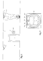
- Figure 1 are on the ceiling 1 of a building corridor in prescribed intervals automatic hazard detectors, here in the form of fire detectors 11 and 12 attached.
- automatic hazard detectors here in the form of fire detectors 11 and 12 attached.
- a door or a passage 2 to another hallway which are equipped with hazard detectors in the same way there is a manual hazard detector, here in Form of a push button detector 30, which on a corridor wall 3rd is mounted.
- Each automatic fire detector 11, 12 is not one represented control center connected and includes at least a bright LED 11.1, 12.1, which is usually the Has the function of an operating status display or with which the Detector is additionally equipped.
- the push button detector 30 includes the in generally accessible only after pressing in a pane Push button 31 or another, manually operable Mechanism of transmission after actuation an analog or digital signal to a control center (not shown) triggers.
- This push button has et al a window in which next to the printed symbol of a burning house three LEDs 30.1, 30.2, 30.3 for Signaling of the states "operation", “alarm” and "fault", which are usually assigned the colors green, red and yellow are arranged. Near the side edges This window has an additional LED on each side 30.4 and 30.5 arranged in the physical shape of an arrow. These LEDs 30.4 and 30.5 can be from the control center be switched from blinking to single.
- Figure 1 speaks the detector 11 for one or more sequelae of fire (Temperature, smoke, etc.) and gives a corresponding one Data telegram to the control center.
- a person presses the push button 30.1 of the push button detector 30, which then also sends an alarm signal to the Central sends.
- the computer in the central office solves that usual reactions intended for fire and Messages.
- the computer also determines the under Taking into account that caused by the alarm signal of the fire detector 11 localized danger location the usable escape routes and the exits to be driven on them, which are safe leading directions.
- the computer generates from this data Control commands that the LED 12.1 of the detector 12 and the corresponding LEDs of everyone on the escape route or routes following, not shown fire detector in a flashing mode relocate, specifically for the individual detectors delayed that for refugees the impression one signaling the direction of escape to be taken Running light is created.
- the computer Alternatively or simultaneously activated the computer in all on the escape route (s) lying push button detectors that LED in the form of a Arrow, which indicates the direction of escape, in the case of Push button detector 30, the LED 30.4 and also offset this into a flashing mode.
Abstract
Description
Die Erfindung betrifft ein Verfahren zur Signalisierung des in einer Gefahrensituation einzuschlagenden Fluchtweges in einem Gebäude mit verteilt angeordneten Gefahrenmeldern, die an eine Gefahrenmeldezentrale angeschlossen sind. Die Erfindung bezieht sich des weiteren auf Gefahrenmelder zur Durchführung dieses Verfahrens.The invention relates to a method for signaling the escape route to be taken in a dangerous situation a building with distributed hazard detectors, which are connected to a hazard alarm center. The The invention further relates to hazard detectors Performing this procedure.
Aus der DE-AS 24 41 071 ist ein Verfahren zur Kenntlichmachung von Fluchtwegen durch Lichtquellen bekannt, die längs des gesamten Fluchtweges verteilt angeordnet sind und ein Lauflicht bilden, dessen Farbe sich in Richtung auf das sichere Ende des Fluchtweges hin zunehmend nach grün verschiebt oder dessen Helligkeit abnimmt oder dessen Rhytmus sich verlangsamt. Den Lichtquellen sind Schallquellen zugeordnet, die gleichzeitig oder verzögert mit den Lichtquellen erregbar sind. Die Lichtquellen können einzeln oder als Lauflicht z.B. durch einen in den Alarmzustand gegangenen Gefahrenmelder aktiviert werden. Dieser bekannte Vorschlag ist nicht in die Praxis umgesetzt worden. Dafür sind vermutlich zwei wesentliche Mängel verantwortlich, nämlich zum einen der erhebliche geräte- und installationstechnische Aufwand, der selbst bei einer Beschränkung lediglich auf Lichtquellen erforderlich wäre und zum anderen der Umstand, dass es sich um eine gewissermaßen statische Lösung handelt, die nicht berücksichtigt, dass es zumindest in größeren Gebäuden mehrere getrennte oder auch sich kreuzende und voneinander abzweigende potentielle Fluchtwege gibt und die in einem konkreten Gefahrenfall zu benützenden, sicheren Fluchtwege von dem Ort abhängen, an dem die Gefahr aufgetreten ist.DE-AS 24 41 071 is a method for identification known as escape routes through light sources are distributed along the entire escape route and form a running light, the color of which is directed towards the safe end of the escape route increasingly shifts to green or whose brightness decreases or whose rhythm slows down. Sound sources are assigned to the light sources, which are simultaneous or delayed with the light sources are excitable. The light sources can be individually or as running light e.g. by one that went into the alarm state Hazard detectors can be activated. This well-known proposal has not been put into practice. Are for probably responsible for two major shortcomings, namely on the one hand, the considerable device and installation technology Effort that even with a limitation only would be required on light sources and secondly the fact that it's a kind of static solution that does not take into account that it is at least in larger buildings several separate or intersecting and potential escape routes there and which are to be used in a specific danger, safe escape routes depend on the place where the Danger has occurred.
Der Erfindung liegt daher die Aufgabe zugrunde, ein Verfahren der einleitend angegebenen Gattung zu schaffen, das mit nur geringem zusätzlichem geräte- und installationstechnischem Aufwand auskommt.The invention is therefore based on the object of a method of the genus specified in the introduction to create the with only a little additional equipment and installation technology Effort.
Diese Aufgabe ist erfindungsgemäß dadurch gelöst, dass die Gefahrenmelder mit Leuchtmitteln ausgestattet werden, die im Gefahrenfall von der Zentrale aus sequentiell nach Art eines Lauflichtes aktivierbar sind, das die von dem Gefahrenort wegführende Richtung des Fluchtweges bezeichnet (Anspruch 1).This object is achieved in that the Hazard detectors can be equipped with lamps that in the event of an emergency, sequentially from the head office in accordance with Art a running light that can be activated from the hazard location designated leading direction of the escape route (Claim 1).
Diese Lösung hat den Vorteil, dass sie einerseits den an sich bekannten Lauflichteffekt auf der Grundlage der ohnehin vorhandenen Gefahrenmelder und deren Installation verwirklicht und andererseits dynamisch arbeitet, d.h. nur die sicheren Fluchtwege und die auf diesen einzuschlagende Richtung in Abhängigkeit von dem Gefahrenort signalisiert. Der Aufwand ist hierfür vergleichsweise gering, denn nach dem Stand der Technik sind zum einen die in einem Gebäude verteilt angeordneten Gefahrenmelder stets an eine rechnergesteuerte Zentrale angeschlossen und werden von dieser auch mit der Versorgungsspannung gespeist, zum anderen stehen als Leuchtmittel inzwischen lichtemittierende Dioden (LEDs) mit hohem Umwandlungswirkungsgrad zur Verfügung, die deshalb im Pulsbetrieb Lichtimpulse hoher Intensität abstrahlen können, ohne dass deswegen die von der Zentrale zur Verfügung gestellte Speiseleistung je Melder merklich erhöht werden muss.This solution has the advantage that on the one hand the well-known chaser effect based on the anyway existing hazard detectors and their installation realized and on the other hand works dynamically, i.e. only that safe escape routes and the routes to be followed Direction signaled depending on the hazard location. The effort for this is comparatively low, because after the state of the art are those in a building Distributed hazard detectors always to a computer-controlled Central connected and are operated by this also supplied with the supply voltage, on the other are now light emitting diodes (LEDs) with high conversion efficiency therefore emit light pulses of high intensity in pulse mode can, without that from the headquarters provided power per detector noticeable must be increased.
Bevorzugt lässt sich das Verfahren in der Weise verwirklichen, dass in der Zentrale eine Datei, die sämtliche Fluchtwege des Gebäudes und die physikalischen Orte sämtlicher Gefahrenmelder umfasst sowie ein Programm zur Ermittlung des oder der zu wählenden Fluchtwege in Abhängigkeit von einer oder mehreren einlaufenden Gefahrenmeldungen gespeichert wird, welches Programm die Daten des Anfangs, der Richtung und des Endes der von dem oder den ermittelten Gefahrenorten wegführenden Fluchtwege und daraus die Folge der Ansteuerbefehle der zu aktivierenden Leuchtmittel der Gefahrenmelder errechnet (Anspruch 2). Diese Ansteuerbefehle werden in der Regel als digitale Datentelegramme an die einzelnen Gefahrenmelder übermittelt.The method can preferably be implemented in such a way that that at the headquarters a file that all Escape routes of the building and the physical locations of all Danger detector includes as well as a program for the determination of the escape route or routes to be chosen depending on of one or more incoming hazard reports which program is saved the data of the beginning, the direction and end of the determined by the one or more Escape routes leading away from danger locations and the result the control commands of the lamps to be activated Risk detector calculated (claim 2). These control commands are usually sent as digital data telegrams the individual hazard detectors transmitted.
Das vorgeschlagene Verfahren kann dadurch ergänzt werden, dass an die Zentrale zusätzlich die Leuchtmittel beleuchteter Fluchtwegkennzeichnungen angeschlossen werden und dass die Zentrale die auf dem/den ermittelten Fluchtweg(en) liegenden Fluchtwegkennzeichnungen in einen Blinkmodus versetzt (Anspruch 3). Anders als bei dem einleitend genannten Verfahren nach dem Stand der Technik werden hierbei nur die nach den örtlichen öffentlich- rechtlichen Vorschriften angebrachten und somit bereits vorhandenen, beleuchteten Fluchtwegkennzeichnungen benutzt. Diese sind häufig von der Gefahrenmeldezentrale aus überwacht und auch steuerbar. Nur wenn dies nicht der Fall ist, entsteht ein verhältnismäßig bescheidener, zusätzlicher Installationsaufwand für den Anschluss der Fluchtwegkennzeichnungen an die Zentrale.The proposed method can be supplemented by that the illuminants are also illuminated at the head office Escape route signs can be connected and that the control center can determine the escape route (s) determined escape route markings in a flashing mode offset (claim 3). In contrast to the introduction mentioned Prior art methods are used here only according to the local public law regulations attached and thus already existing, illuminated Emergency exit signs used. These are often monitored and also from the alarm center controllable. Only if this is not the case does one arise relatively modest, additional installation effort for connecting the escape route signs the headquarters.
Nach einer Weiterbildung dieses Verfahrens schaltet die Zentrale die Leuchtmittel derjenigen Fluchtwegkennzeichnungen ab, die im jeweiligen Gefahrenfall ungeeignete oder gefährliche Fluchtwege bezeichnen (Anspruch 4). Dies ist eine wesentliche Verbesserung der derzeitigen Situation, bei der nach im Gefahrenfall erfolgter Aktivierung sämtliche konventionellen, beleuchteten Fluchtwegrichtungsweiser und Notausgangskennzeichnungen aufleuchten, also auch diejenigen, deren Benutzung statt von dem Gefahrenort weg näher an diesen hinführen. After further training of this procedure, the Central the illuminants of those escape route signs from which is unsuitable or denote dangerous escape routes (claim 4). This is a significant improvement in the current situation, all after activation in the event of danger conventional, illuminated escape route sign and emergency exit signs light up, also those whose use instead of away from the hazard lead closer to it.
Wie die physikalischen Orte der Gefahrenmelder, die zur Erzeugung des Lauflichteffektes eingesetzt werden, kön-nen auch die physikalischen Orte der beleuchteten Fluchtwegkennzeichnungen in der Datei in der Zentrale abgelegt und in dem Fluchtwegermittlungsprogramm mitverarbeitet werden (Anspruch 5).Like the physical locations of the hazard detectors used for Generation of the chaser effect can be used also the physical locations of the illuminated escape route signs filed in the file at the headquarters and be processed in the escape route determination program (Claim 5).
Die der Erfindung zugrunde liegende Aufgabe wird des weiteren durch den Einsatz automatischer oder handbetätigter Gefahrenmelder mit in deren Ruhezustand grün leuchtender LED dadurch gelöst, dass die-se LED im Gefahrenfall von der Zentrale aus in einen Blinkmodus schaltbar ist (Anspruch 6). Dazu ist insbesondere bei mikroprozessorgesteuerten Gefahrenmeldern eine in der Regel nur geringfügige Änderung der Software und allenfalls ein zusätzlicher Halbleiterschalter notwendig.The object underlying the invention is further through the use of automatic or manual Hazard detectors with green lights in their idle state LED solved by the fact that this LED from the Central can be switched to a flashing mode (claim 6). This is particularly the case with microprocessor-controlled hazard detectors a generally minor change the software and possibly an additional semiconductor switch necessary.
Aus Gründen der Einsparung an Versorgungsleistung werden allerdings in üblichen Gefahrenmeldern zur Signalisierung deren Betriebszustandes LEDs mit geringer Stromaufnahme und entsprechend geringer Leuchtdichte oder Strahlungsintensität eingesetzt. Statt diese LED durch eine entsprechend leuchtstärkere LED zu ersetzen, kann der Gefahrenmelder mit mindestens einer zusätzlichen, leuchtstarken, grünleuchtenden LED ausgestattet werden, die nur im Gefahrenfall leuchtet, uzw. in einem von der Zentrale aus schaltbaren Blinkmodus (Anspruch 7).For the sake of saving on utility services however, in usual hazard detectors for signaling their operating status LEDs with low power consumption and correspondingly low luminance or radiation intensity used. Instead of this LED by a corresponding The hazard detector can replace more powerful LEDs at least one additional, bright, green glowing LEDs that only light up in the event of danger, uzw. in a flashing mode that can be switched from the control center (Claim 7).
Es empfiehlt sich, die zusätzliche LED körperlich als Pfeil auszubilden (Anspruch 8). Selbstverständlich können, falls zwei alternative Fluchtwegrichtungen in Betracht kommen, zwei derartige zusätzliche LEDs je Melder vorgesehen sein.It is recommended to physically use the additional LED as an arrow train (claim 8). Of course, if two alternative escape routes can be considered, two such additional LEDs can be provided per detector.
Die Gefahrenmelder können automatische Melder sein, die auf bestimmte Merkmale wie Temperatur, Rauch, Flamme, bestimmte Gase oder andere gefahrentypische physikalische Erscheinunngen ansprechen. Ebenso gut eignen sich auch manuelle Gefahrenmelder, die in der Regel wandmontierbar sind, in einer Not- oder Gefahrensituation durch Betätigen eines Druckknopfes oder ähnliches ausgelöst werden und dann eine entsprechende Meldung an die Zentrale absetzen.The hazard detectors can be automatic detectors that point to certain characteristics such as temperature, smoke, flame, certain Gases or other physical phenomena typical of the hazard speak to. Manual hazard detectors are also suitable, which are usually wall-mountable, in an emergency or dangerous situation by pressing one Push button or the like are triggered and then one Send the corresponding message to the head office.
Insbesondere ein manueller wandmontierbarer Gefahrenmelder kann zwei als in entgegengesetzte Richtungen weisende Pfeile ausgestaltete LEDs umfassen, von denen entweder die eine oder die andere von der Zentrale aus situationsgerecht in einen Blinkmodus schaltbar ist.In particular, a manual wall-mounted hazard detector can have two arrows pointing in opposite directions designed LEDs include, of which either one or the other one from the head office, depending on the situation a flashing mode can be switched.
Das Verfahren nach der Erfindung wird nachfolgend anhand einer schematischen Zeichnung erläutert. Es zeigt:
- Fig. 1
- die Wand und die Decke eines Fluchtweges in einem Gebäude in schematischer Vereinfachung und
- Fig. 2
- die Einzelheit "X" in Fig. 1, d.h. einen manuellen Gefahrenmelder in vergrößerter Darstellung.
- Fig. 1
- the wall and the ceiling of an escape route in a building in a schematic simplification and
- Fig. 2
- the detail "X" in Fig. 1, ie a manual hazard detector in an enlarged view.
Gemäß Figur 1 sind an der Decke 1 eines Gebäudeflurs in
vorgeschriebenen Abständen automatische Gefahrenmelder,
hier in Form von Brandmeldern 11 und 12, angebracht. Neben
einer Tür oder einem Durchgang 2 zu einem weiteren Flur,
der in gleicher Weise mit Gefahrenmeldern ausgestattet sein
kann, befindet sich ein manueller Gefahrenmelder, hier in
Form eines Druckknopfmelders 30, der an einer Flurwand 3
montiert ist.According to Figure 1 are on the
Jeder automatische Brandmelder 11, 12 ist an eine nicht
dargestellte Zentrale angeschlossen und umfasst mindestens
eine leuchtstarke LED 11.1, 12.1, die normalerweise die
Funktion einer Betriebszustandsanzeige hat oder mit der der
Melder zusätzlich ausgestattet ist. Each
Der Druckknopfmelder 30 umfasst gemäß Fig. 2 u.a. den in
der Regel erst nach dem Eindrücken einer Scheibe zugänglichen
Druckknopf 31 oder auch einen anderen, manuell betätigbaren
Mechanismus, der nach dem Betätigen die Übermittlung
eines analogen oder digitalen Signals an eine Zentrale
(nicht dargestellt) auslöst. Dieser Druckknopfmelder hat
u.a. ein Fenster, in welchem neben dem gedruckten Symbol
eines brennenden Hauses drei LEDs 30.1, 30.2, 30.3 zur
Signalisierung der Zustände "Betrieb", "Alarm" und "Störung",
denen gewöhnlich die Farben grün, rot und gelb zugeordnet
sind, angeordnet sind. Nahe den Seitenrändern
dieses Fensters ist auf jeder Seite eine zusätzliche LED
30.4 und 30.5 in der körperlichen Form eines Pfeils angeordnet.
Diese LEDs 30.4 und 30.5 können von der Zentrale
aus eineln in einen Blinkzustand versetzt werden.According to FIG. 2, the
In der in Figur 1 dargestellten Gefahrensituation spricht
der Melder 11 auf eine oder mehrere Brandfolgeerscheinungen
(Temperatur, Rauch usw.) an und gibt ein entsprechendes
Datentelegramm an die Zentrale. Alternativ oder zusätzlich
drückt eine Person den Druckknopf 30.1 des Druckknopfmelders
30, der daraufhin ebenfalls ein Alarmsignal an die
Zentrale sendet. Der Rechner in der Zentrale löst dann die
üblichen, für den Brandfall vorgesehenen Reaktionen und
Meldungen aus. Zusätzlich ermittelt der Rechner die unter
Berücksichtigung des durch das Alarmsignal des Brandmelders
11 lokalisierten Gefahrenortes die benutzbaren Fluchtwege
und die auf diesen einzuschlagenden, zu sicheren Ausgängen
führenden Richtungen. Aus diesen Daten generiert der Rechner
Ansteuerbefehle, die die LED 12.1 des Melders 12 und
die entsprechenden LEDs aller auf dem oder den Fluchtwegen
folgenden, nicht dargestellten Brandmelder in einen Blinkmodus
versetzen, und zwar für die einzelnen Melder derart
zeitversetzt, dass für flüchtende Personen der Eindruck
eines die einzuschlagende Fluchtrichtung signalisierenden
Lauflichtes entsteht. Alternativ oder gleichzeitig aktiviert
der Rechner in allen auf dem oder den Fluchtwegen
liegenden Druckknopfmeldern diejenige LED in Form eines
Pfeiles, die die Fluchtrichtung bezeichnet, im Fall des
Druckknopfmelders 30 also die LED 30.4 und versetzt auch
diese in einen Blinkmodus. Dabei können wahlweise entweder
alle Druckknopfmelder mit dem gleichen Blinktakt angesteuert
werden oder die Ansteuerbefehle können wie diejenigen
für die automatischen Brandmelder zeitversetzt und gegebenenfalls
zu diesem synchron erzeugt werden, so dass die
entsprechenden LEDs aufeinanderfolgender Druckknopfmelder
einen eigenen Lauflichteffekt oder einen in den von den
automatischen Brandmeldern erzeugten Lauflichteffekt einbezogenen
Lauflichteffekt erzeugen.In the dangerous situation shown in Figure 1 speaks
the
Claims (9)
Applications Claiming Priority (2)
| Application Number | Priority Date | Filing Date | Title |
|---|---|---|---|
| DE10246033A DE10246033B4 (en) | 2002-10-02 | 2002-10-02 | flight control system |
| DE10246033 | 2002-10-02 |
Publications (1)
| Publication Number | Publication Date |
|---|---|
| EP1408466A1 true EP1408466A1 (en) | 2004-04-14 |
Family
ID=32010108
Family Applications (1)
| Application Number | Title | Priority Date | Filing Date |
|---|---|---|---|
| EP03019001A Ceased EP1408466A1 (en) | 2002-10-02 | 2003-08-21 | Method and hazard detector to signalize an escape route |
Country Status (3)
| Country | Link |
|---|---|
| US (1) | US6998960B2 (en) |
| EP (1) | EP1408466A1 (en) |
| DE (1) | DE10246033B4 (en) |
Cited By (5)
| Publication number | Priority date | Publication date | Assignee | Title |
|---|---|---|---|---|
| EP2118865A1 (en) * | 2007-02-28 | 2009-11-18 | Honeywell International Inc. | Detector/module integrated emergency signs |
| DE102008042611A1 (en) | 2008-10-06 | 2010-04-08 | Robert Bosch Gmbh | Signaling device for signaling an escape route and escape route signaling system |
| DE202012100157U1 (en) | 2012-01-17 | 2013-01-25 | P.E.R. Flucht- Und Rettungsleitsysteme Gmbh | Dynamic escape and rescue control system |
| EP3082116A4 (en) * | 2013-12-11 | 2017-08-02 | TNK Corporation Ltd. | Guidance system |
| DE102012100348B4 (en) | 2012-01-17 | 2018-08-16 | P.E.R. Flucht- Und Rettungsleitsysteme Gmbh | DYNAMIC FLIGHT AND RESCUE CONTROL SYSTEM |
Families Citing this family (62)
| Publication number | Priority date | Publication date | Assignee | Title |
|---|---|---|---|---|
| US6773360B2 (en) * | 2002-11-08 | 2004-08-10 | Taylor Made Golf Company, Inc. | Golf club head having a removable weight |
| US7061392B2 (en) * | 2003-12-12 | 2006-06-13 | Honeywell International, Inc. | System and method of disabling an evacuation location device |
| US7619538B1 (en) * | 2005-05-12 | 2009-11-17 | Sanrose, LLC | Programmable, directing evacuation systems: apparatus and method |
| KR100690403B1 (en) * | 2005-11-02 | 2007-03-09 | (주)인세이프테크 | Power supply checking device using RF system |
| US7800511B1 (en) * | 2006-03-07 | 2010-09-21 | Living Space International, Inc. | Emergency lighting system |
| US7905645B2 (en) * | 2007-11-15 | 2011-03-15 | Batti Stephen A | Illuminated floor mat |
| DE102007061754A1 (en) * | 2007-12-20 | 2009-06-25 | Elektro Grundler Ges.M.B.H. & Co. Kg | Evacuation device and escape route indicator for this |
| US8118447B2 (en) | 2007-12-20 | 2012-02-21 | Altair Engineering, Inc. | LED lighting apparatus with swivel connection |
| US7712918B2 (en) | 2007-12-21 | 2010-05-11 | Altair Engineering , Inc. | Light distribution using a light emitting diode assembly |
| US8120481B2 (en) * | 2008-02-12 | 2012-02-21 | Mark Gottlieb | Emergency services notification station and door unlock device |
| EP2256708A4 (en) * | 2008-03-14 | 2012-04-18 | Hochiki Co | Disaster-preventing terminal system |
| US8360599B2 (en) | 2008-05-23 | 2013-01-29 | Ilumisys, Inc. | Electric shock resistant L.E.D. based light |
| FI122351B (en) * | 2008-06-19 | 2011-12-15 | Marimils Oy | Procedure, system and device for display, guidance and warning |
| US7976196B2 (en) | 2008-07-09 | 2011-07-12 | Altair Engineering, Inc. | Method of forming LED-based light and resulting LED-based light |
| US7946729B2 (en) | 2008-07-31 | 2011-05-24 | Altair Engineering, Inc. | Fluorescent tube replacement having longitudinally oriented LEDs |
| US8674626B2 (en) | 2008-09-02 | 2014-03-18 | Ilumisys, Inc. | LED lamp failure alerting system |
| US8256924B2 (en) | 2008-09-15 | 2012-09-04 | Ilumisys, Inc. | LED-based light having rapidly oscillating LEDs |
| US8901823B2 (en) | 2008-10-24 | 2014-12-02 | Ilumisys, Inc. | Light and light sensor |
| US8444292B2 (en) | 2008-10-24 | 2013-05-21 | Ilumisys, Inc. | End cap substitute for LED-based tube replacement light |
| US8324817B2 (en) | 2008-10-24 | 2012-12-04 | Ilumisys, Inc. | Light and light sensor |
| US8214084B2 (en) | 2008-10-24 | 2012-07-03 | Ilumisys, Inc. | Integration of LED lighting with building controls |
| US8653984B2 (en) * | 2008-10-24 | 2014-02-18 | Ilumisys, Inc. | Integration of LED lighting control with emergency notification systems |
| US7938562B2 (en) | 2008-10-24 | 2011-05-10 | Altair Engineering, Inc. | Lighting including integral communication apparatus |
| GB0820606D0 (en) * | 2008-11-11 | 2008-12-17 | Patterson Kieran | Route guidance and evacuation system |
| NL2002295C2 (en) * | 2008-12-05 | 2009-12-14 | Michel Robert Ten Wolde | Escape route illumination device for e.g. hotel, has lighting device mounted to wall at specific mounting height from floor, where lighting device illuminates predetermined area of floor |
| US9679449B2 (en) | 2008-12-30 | 2017-06-13 | Oneevent Technologies, Inc. | Evacuation system |
| US8749392B2 (en) | 2008-12-30 | 2014-06-10 | Oneevent Technologies, Inc. | Evacuation system |
| US8556452B2 (en) | 2009-01-15 | 2013-10-15 | Ilumisys, Inc. | LED lens |
| US8362710B2 (en) | 2009-01-21 | 2013-01-29 | Ilumisys, Inc. | Direct AC-to-DC converter for passive component minimization and universal operation of LED arrays |
| US8664880B2 (en) | 2009-01-21 | 2014-03-04 | Ilumisys, Inc. | Ballast/line detection circuit for fluorescent replacement lamps |
| US9799205B2 (en) | 2013-07-15 | 2017-10-24 | Oneevent Technologies, Inc. | Owner controlled evacuation system with notification and route guidance provided by a user device |
| US8330381B2 (en) | 2009-05-14 | 2012-12-11 | Ilumisys, Inc. | Electronic circuit for DC conversion of fluorescent lighting ballast |
| US8299695B2 (en) | 2009-06-02 | 2012-10-30 | Ilumisys, Inc. | Screw-in LED bulb comprising a base having outwardly projecting nodes |
| EP2446715A4 (en) | 2009-06-23 | 2013-09-11 | Ilumisys Inc | Illumination device including leds and a switching power control system |
| WO2011119958A1 (en) | 2010-03-26 | 2011-09-29 | Altair Engineering, Inc. | Inside-out led bulb |
| EP2553316B8 (en) | 2010-03-26 | 2015-07-08 | iLumisys, Inc. | Led light tube with dual sided light distribution |
| EP2553320A4 (en) * | 2010-03-26 | 2014-06-18 | Ilumisys Inc | Led light with thermoelectric generator |
| US8454193B2 (en) | 2010-07-08 | 2013-06-04 | Ilumisys, Inc. | Independent modules for LED fluorescent light tube replacement |
| EP2593714A2 (en) | 2010-07-12 | 2013-05-22 | iLumisys, Inc. | Circuit board mount for led light tube |
| US8523394B2 (en) | 2010-10-29 | 2013-09-03 | Ilumisys, Inc. | Mechanisms for reducing risk of shock during installation of light tube |
| KR20120064543A (en) * | 2010-12-09 | 2012-06-19 | 한국전자통신연구원 | Apparatus and method for light indication |
| US8870415B2 (en) | 2010-12-09 | 2014-10-28 | Ilumisys, Inc. | LED fluorescent tube replacement light with reduced shock hazard |
| US9072171B2 (en) | 2011-08-24 | 2015-06-30 | Ilumisys, Inc. | Circuit board mount for LED light |
| US9184518B2 (en) | 2012-03-02 | 2015-11-10 | Ilumisys, Inc. | Electrical connector header for an LED-based light |
| WO2014008463A1 (en) | 2012-07-06 | 2014-01-09 | Ilumisys, Inc. | Power supply assembly for led-based light tube |
| US9271367B2 (en) | 2012-07-09 | 2016-02-23 | Ilumisys, Inc. | System and method for controlling operation of an LED-based light |
| US9285084B2 (en) | 2013-03-14 | 2016-03-15 | Ilumisys, Inc. | Diffusers for LED-based lights |
| US9267650B2 (en) | 2013-10-09 | 2016-02-23 | Ilumisys, Inc. | Lens for an LED-based light |
| WO2015112437A1 (en) | 2014-01-22 | 2015-07-30 | Ilumisys, Inc. | Led-based light with addressed leds |
| WO2015148563A2 (en) * | 2014-03-25 | 2015-10-01 | Osram Sylvania Inc. | Techniques for indoor navigation with hazard avoidance via light-based communication |
| EP3123638B1 (en) | 2014-03-25 | 2018-07-18 | Osram Sylvania Inc. | Techniques for indoor navigation with occupancy tracking and location tracking via light-based communication |
| US10102585B1 (en) | 2014-04-25 | 2018-10-16 | State Farm Mutual Automobile Insurance Company | Systems and methods for automatically mitigating risk of property damage |
| US9510400B2 (en) | 2014-05-13 | 2016-11-29 | Ilumisys, Inc. | User input systems for an LED-based light |
| US10515372B1 (en) * | 2014-10-07 | 2019-12-24 | State Farm Mutual Automobile Insurance Company | Systems and methods for managing building code compliance for a property |
| DE202015100095U1 (en) | 2015-01-12 | 2015-02-06 | Kai Knierim | Device for escape and rescue route management |
| US10161568B2 (en) | 2015-06-01 | 2018-12-25 | Ilumisys, Inc. | LED-based light with canted outer walls |
| US11062574B2 (en) * | 2016-01-22 | 2021-07-13 | Tyco Fire & Security Gmbh | Strobe notification appliance and emergency lighting appliance with directional information |
| CA2929349A1 (en) * | 2016-04-29 | 2017-10-29 | Hubbell Incorporated | Light fixture |
| US10011460B2 (en) | 2016-09-27 | 2018-07-03 | Otis Elevator Company | Elevator dynamic displays for messaging and communication |
| CN110895723A (en) * | 2018-09-13 | 2020-03-20 | 开利公司 | Fire detection system-intelligent fire signalling for fire equipment |
| US11282350B2 (en) * | 2019-06-25 | 2022-03-22 | AVIDEA Group, Inc. | Firearm discharge detecting and semaphoring system and method |
| US11390392B2 (en) | 2019-11-18 | 2022-07-19 | Air Cruisers Company, LLC | Running/chasing lights for evacuation systems |
Citations (2)
| Publication number | Priority date | Publication date | Assignee | Title |
|---|---|---|---|---|
| WO1996025729A1 (en) * | 1995-02-17 | 1996-08-22 | Rijlaarsdam Design Holding B.V. | Escape route indication system |
| WO2000014693A1 (en) * | 1998-09-09 | 2000-03-16 | Siemens Building Technologies Ag | Fire alarm and fire alarm system |
Family Cites Families (15)
| Publication number | Priority date | Publication date | Assignee | Title |
|---|---|---|---|---|
| DE2441073C3 (en) * | 1974-08-27 | 1986-07-10 | Esser Sicherheitstechnik GmbH, 4040 Neuss | Arrangement for the identification of escape routes by means of light sources |
| US4385586A (en) * | 1981-09-04 | 1983-05-31 | Schriever Frederick G | Escape/rescue system |
| US4531114A (en) * | 1982-05-06 | 1985-07-23 | Safety Intelligence Systems | Intelligent fire safety system |
| US4737764A (en) * | 1986-05-30 | 1988-04-12 | Collins & Aikman Corporation | Modular floor covering units with built-in lighting |
| US4754266A (en) * | 1987-01-07 | 1988-06-28 | Shand Kevin J | Traffic director |
| GB2215105A (en) * | 1988-02-16 | 1989-09-13 | Richard William Henry Ford | Personnel evacuation system |
| GB2223871A (en) * | 1988-09-29 | 1990-04-18 | Colt Int Ltd | Escape route indication system |
| US5019805A (en) * | 1989-02-03 | 1991-05-28 | Flash-Alert Inc. | Smoke detector with strobed visual alarm and remote alarm coupling |
| DE4241862C2 (en) * | 1992-12-11 | 2001-03-01 | Ceag Sicherheitstechnik Gmbh | Security system and procedure with which the security system is operated |
| JPH06231378A (en) * | 1993-02-02 | 1994-08-19 | Souji Kobayashi | Refuging exit and refuging passage guiding device |
| US6025773A (en) * | 1998-02-09 | 2000-02-15 | Bresnan; William P. | Tactile safety guidance system for low visibility situations |
| US6150943A (en) * | 1999-07-14 | 2000-11-21 | American Xtal Technology, Inc. | Laser director for fire evacuation path |
| DE10001744A1 (en) * | 2000-01-17 | 2001-07-19 | Inprotec Innovative Produktion | Advice and/or emergency indicator light has light emitting diodes distributed on board and electrically connected to be driven individually or in groups by controller as variable display |
| DE10048904A1 (en) * | 2000-10-02 | 2002-05-08 | Willing Gmbh Dr Ing | Escape sign lamp arrangement has light emitting diodes generally supplied with lower current when supplied by battery than during normal operation with power supplied from mains |
| GB2370675B (en) * | 2000-11-15 | 2003-04-30 | Maurice Bligh | Colour-coded evacuation signalling system |
-
2002
- 2002-10-02 DE DE10246033A patent/DE10246033B4/en not_active Revoked
-
2003
- 2003-08-21 EP EP03019001A patent/EP1408466A1/en not_active Ceased
- 2003-09-29 US US10/671,631 patent/US6998960B2/en not_active Expired - Lifetime
Patent Citations (2)
| Publication number | Priority date | Publication date | Assignee | Title |
|---|---|---|---|---|
| WO1996025729A1 (en) * | 1995-02-17 | 1996-08-22 | Rijlaarsdam Design Holding B.V. | Escape route indication system |
| WO2000014693A1 (en) * | 1998-09-09 | 2000-03-16 | Siemens Building Technologies Ag | Fire alarm and fire alarm system |
Cited By (6)
| Publication number | Priority date | Publication date | Assignee | Title |
|---|---|---|---|---|
| EP2118865A1 (en) * | 2007-02-28 | 2009-11-18 | Honeywell International Inc. | Detector/module integrated emergency signs |
| EP2118865A4 (en) * | 2007-02-28 | 2011-11-02 | Honeywell Int Inc | Detector/module integrated emergency signs |
| DE102008042611A1 (en) | 2008-10-06 | 2010-04-08 | Robert Bosch Gmbh | Signaling device for signaling an escape route and escape route signaling system |
| DE202012100157U1 (en) | 2012-01-17 | 2013-01-25 | P.E.R. Flucht- Und Rettungsleitsysteme Gmbh | Dynamic escape and rescue control system |
| DE102012100348B4 (en) | 2012-01-17 | 2018-08-16 | P.E.R. Flucht- Und Rettungsleitsysteme Gmbh | DYNAMIC FLIGHT AND RESCUE CONTROL SYSTEM |
| EP3082116A4 (en) * | 2013-12-11 | 2017-08-02 | TNK Corporation Ltd. | Guidance system |
Also Published As
| Publication number | Publication date |
|---|---|
| US20040075572A1 (en) | 2004-04-22 |
| DE10246033A1 (en) | 2004-04-22 |
| DE10246033B4 (en) | 2006-02-23 |
| US6998960B2 (en) | 2006-02-14 |
Similar Documents
| Publication | Publication Date | Title |
|---|---|---|
| DE10246033B4 (en) | flight control system | |
| WO2006086812A2 (en) | Evacuation system comprising rescue guide lights | |
| DE102005008996B4 (en) | Method and device for setting a continuous dimming operation or a dimming operation with only two levels | |
| DE102008017656A1 (en) | Evacuation sign e.g. emergency light, for electrical system of building installation, has laser diode projecting character as guideline, and LED operating during failure of general lighting of sign | |
| DE19722406B4 (en) | Escape sign light and security system | |
| EP1842991B1 (en) | Emergency stop terminal with combined indicator | |
| DE19644126B4 (en) | Escape route signaling system | |
| DE202004002248U1 (en) | Handrail, in particular, for stairs in buildings open to general public incorporates and substantially surrounds at least one light source | |
| DE10001744A1 (en) | Advice and/or emergency indicator light has light emitting diodes distributed on board and electrically connected to be driven individually or in groups by controller as variable display | |
| DE10353523A1 (en) | Balustrade element for staircase has at least one opening near internal cavity, light source, especially light emitting diode, arranged in cavity with which cavity can be illuminated | |
| EP0903966B1 (en) | Lighting system | |
| EP1471776A1 (en) | Control apparatus for a lighting fixture | |
| DE102006043867B4 (en) | Method and installation for identifying a hazard detector | |
| DE10234300A1 (en) | Monitored safety button, allowing opening of doors or windows in emergency, is circular and surrounded by illumination | |
| DE10201131A1 (en) | Lamp body has base mounted microprocessor to control individual light sources provided within common bulb | |
| DE4031364A1 (en) | Control data manual entry device for technical systems - has keyboard in plug-in module, alphanumeric display, microcomputer and text ROM | |
| DE504716C (en) | Lighting device for lighthouses | |
| DE10002889A1 (en) | Light control system for at least one light track; has control device to control light output, e.g. brightness, of at least one lamp of light track through control bus and has synchronization device | |
| CN201117045Y (en) | Device for detecting induction signal | |
| WO2011123876A1 (en) | Method for illuminating a room | |
| DE202004001695U1 (en) | Combined fireproof paneling and lighting unit | |
| EP3018271B1 (en) | Panic bar | |
| DE2524885A1 (en) | Emergency exit lighting and signpost - has emergency lamps with electronic flasher unit behind partially transparent hood | |
| EP0105073B1 (en) | Signalling and/or alarm and/or control system | |
| DE102014111441A1 (en) | lighting device |
Legal Events
| Date | Code | Title | Description |
|---|---|---|---|
| PUAI | Public reference made under article 153(3) epc to a published international application that has entered the european phase |
Free format text: ORIGINAL CODE: 0009012 |
|
| AK | Designated contracting states |
Kind code of ref document: A1 Designated state(s): AT BE BG CH CY CZ DE DK EE ES FI FR GB GR HU IE IT LI LU MC NL PT RO SE SI SK TR |
|
| AX | Request for extension of the european patent |
Extension state: AL LT LV MK |
|
| 17P | Request for examination filed |
Effective date: 20040219 |
|
| 17Q | First examination report despatched |
Effective date: 20040819 |
|
| AKX | Designation fees paid |
Designated state(s): AT BE BG CH CY CZ DE DK EE ES FI FR GB GR HU IE IT LI LU MC NL PT RO SE SI SK TR |
|
| AXX | Extension fees paid |
Extension state: LV Payment date: 20040219 Extension state: LT Payment date: 20040219 |
|
| STAA | Information on the status of an ep patent application or granted ep patent |
Free format text: STATUS: THE APPLICATION HAS BEEN REFUSED |
|
| 18R | Application refused |
Effective date: 20051230 |