EP1408276A2 - Illumination system using detectors - Google Patents
Illumination system using detectors Download PDFInfo
- Publication number
- EP1408276A2 EP1408276A2 EP03020936A EP03020936A EP1408276A2 EP 1408276 A2 EP1408276 A2 EP 1408276A2 EP 03020936 A EP03020936 A EP 03020936A EP 03020936 A EP03020936 A EP 03020936A EP 1408276 A2 EP1408276 A2 EP 1408276A2
- Authority
- EP
- European Patent Office
- Prior art keywords
- sensors
- light sources
- control unit
- light
- lighting
- Prior art date
- Legal status (The legal status is an assumption and is not a legal conclusion. Google has not performed a legal analysis and makes no representation as to the accuracy of the status listed.)
- Granted
Links
Images


Classifications
-
- E—FIXED CONSTRUCTIONS
- E04—BUILDING
- E04B—GENERAL BUILDING CONSTRUCTIONS; WALLS, e.g. PARTITIONS; ROOFS; FLOORS; CEILINGS; INSULATION OR OTHER PROTECTION OF BUILDINGS
- E04B9/00—Ceilings; Construction of ceilings, e.g. false ceilings; Ceiling construction with regard to insulation
- E04B9/32—Translucent ceilings, i.e. permitting both the transmission and diffusion of light
-
- E—FIXED CONSTRUCTIONS
- E04—BUILDING
- E04B—GENERAL BUILDING CONSTRUCTIONS; WALLS, e.g. PARTITIONS; ROOFS; FLOORS; CEILINGS; INSULATION OR OTHER PROTECTION OF BUILDINGS
- E04B5/00—Floors; Floor construction with regard to insulation; Connections specially adapted therefor
- E04B5/46—Special adaptation of floors for transmission of light, e.g. by inserts of glass
-
- E—FIXED CONSTRUCTIONS
- E04—BUILDING
- E04B—GENERAL BUILDING CONSTRUCTIONS; WALLS, e.g. PARTITIONS; ROOFS; FLOORS; CEILINGS; INSULATION OR OTHER PROTECTION OF BUILDINGS
- E04B9/00—Ceilings; Construction of ceilings, e.g. false ceilings; Ceiling construction with regard to insulation
- E04B9/30—Ceilings; Construction of ceilings, e.g. false ceilings; Ceiling construction with regard to insulation characterised by edge details of the ceiling; e.g. securing to an adjacent wall
- E04B9/303—Ceilings; Construction of ceilings, e.g. false ceilings; Ceiling construction with regard to insulation characterised by edge details of the ceiling; e.g. securing to an adjacent wall for flexible tensioned membranes
-
- F—MECHANICAL ENGINEERING; LIGHTING; HEATING; WEAPONS; BLASTING
- F21—LIGHTING
- F21S—NON-PORTABLE LIGHTING DEVICES; SYSTEMS THEREOF; VEHICLE LIGHTING DEVICES SPECIALLY ADAPTED FOR VEHICLE EXTERIORS
- F21S2/00—Systems of lighting devices, not provided for in main groups F21S4/00 - F21S10/00 or F21S19/00, e.g. of modular construction
-
- F—MECHANICAL ENGINEERING; LIGHTING; HEATING; WEAPONS; BLASTING
- F21—LIGHTING
- F21V—FUNCTIONAL FEATURES OR DETAILS OF LIGHTING DEVICES OR SYSTEMS THEREOF; STRUCTURAL COMBINATIONS OF LIGHTING DEVICES WITH OTHER ARTICLES, NOT OTHERWISE PROVIDED FOR
- F21V23/00—Arrangement of electric circuit elements in or on lighting devices
- F21V23/04—Arrangement of electric circuit elements in or on lighting devices the elements being switches
- F21V23/0442—Arrangement of electric circuit elements in or on lighting devices the elements being switches activated by means of a sensor, e.g. motion or photodetectors
- F21V23/0471—Arrangement of electric circuit elements in or on lighting devices the elements being switches activated by means of a sensor, e.g. motion or photodetectors the sensor detecting the proximity, the presence or the movement of an object or a person
-
- F—MECHANICAL ENGINEERING; LIGHTING; HEATING; WEAPONS; BLASTING
- F21—LIGHTING
- F21V—FUNCTIONAL FEATURES OR DETAILS OF LIGHTING DEVICES OR SYSTEMS THEREOF; STRUCTURAL COMBINATIONS OF LIGHTING DEVICES WITH OTHER ARTICLES, NOT OTHERWISE PROVIDED FOR
- F21V23/00—Arrangement of electric circuit elements in or on lighting devices
- F21V23/04—Arrangement of electric circuit elements in or on lighting devices the elements being switches
- F21V23/0442—Arrangement of electric circuit elements in or on lighting devices the elements being switches activated by means of a sensor, e.g. motion or photodetectors
- F21V23/0485—Arrangement of electric circuit elements in or on lighting devices the elements being switches activated by means of a sensor, e.g. motion or photodetectors the sensor sensing the physical interaction between a user and certain areas located on the lighting device, e.g. a touch sensor
-
- F—MECHANICAL ENGINEERING; LIGHTING; HEATING; WEAPONS; BLASTING
- F21—LIGHTING
- F21V—FUNCTIONAL FEATURES OR DETAILS OF LIGHTING DEVICES OR SYSTEMS THEREOF; STRUCTURAL COMBINATIONS OF LIGHTING DEVICES WITH OTHER ARTICLES, NOT OTHERWISE PROVIDED FOR
- F21V3/00—Globes; Bowls; Cover glasses
-
- H—ELECTRICITY
- H05—ELECTRIC TECHNIQUES NOT OTHERWISE PROVIDED FOR
- H05B—ELECTRIC HEATING; ELECTRIC LIGHT SOURCES NOT OTHERWISE PROVIDED FOR; CIRCUIT ARRANGEMENTS FOR ELECTRIC LIGHT SOURCES, IN GENERAL
- H05B47/00—Circuit arrangements for operating light sources in general, i.e. where the type of light source is not relevant
- H05B47/10—Controlling the light source
- H05B47/105—Controlling the light source in response to determined parameters
- H05B47/115—Controlling the light source in response to determined parameters by determining the presence or movement of objects or living beings
-
- Y—GENERAL TAGGING OF NEW TECHNOLOGICAL DEVELOPMENTS; GENERAL TAGGING OF CROSS-SECTIONAL TECHNOLOGIES SPANNING OVER SEVERAL SECTIONS OF THE IPC; TECHNICAL SUBJECTS COVERED BY FORMER USPC CROSS-REFERENCE ART COLLECTIONS [XRACs] AND DIGESTS
- Y02—TECHNOLOGIES OR APPLICATIONS FOR MITIGATION OR ADAPTATION AGAINST CLIMATE CHANGE
- Y02B—CLIMATE CHANGE MITIGATION TECHNOLOGIES RELATED TO BUILDINGS, e.g. HOUSING, HOUSE APPLIANCES OR RELATED END-USER APPLICATIONS
- Y02B20/00—Energy efficient lighting technologies, e.g. halogen lamps or gas discharge lamps
- Y02B20/40—Control techniques providing energy savings, e.g. smart controller or presence detection
Definitions
- the invention relates to a lighting device and a method for lighting of objects with several controllable light sources with the characteristics of Preamble of the independent claims.
- Lighting devices of the generic type are preferred for suspended ceilings and possibly also used for walls, whereby from Apart from exceptions, the light sources are arranged behind a diffuser.
- Large area luminaires can also be single, distributed and together Combined diffuser elements for illumination or individual ones distributed in the room Lighting fixtures can be used. This gives the architect options for light planning without visible light sources is offered, which differs significantly from Stand out from conventional lighting systems and the give the architect design freedom.
- the lighting devices can be used with light sources in different colors be equipped and enable each one with complex controls Artistically staging differentiated lighting situations, for the viewer due to the unrecognizable light sources and the use of a diffuser pleasant color variations are generated, which in connection with for example, acoustic reproductions cause certain mood effects.
- Usually light sources with the three primary colors are used different intensities of the three basic colors a freely selectable and individual Let the color spectrum emerge.
- the invention is therefore based on the object, one compared to the known Control technology to show improved lighting control, which is a partial, unconsciously influencing the illumination by a viewer or visitor allows.
- sensors first an object, a visitor, for example, then the exact position of the object is determined and finally the control unit is controlled so that the Lighting device shows a greater or the maximum brightness where is the position of the object.
- This can include an area around the object be understood. Any type of sensor can be used, which in the Is able to grasp a person or an object. Depending on the area of application and the objects to be detected are ultrasound sensors, infrared motion detectors, capacitive proximity switches and the like in question. to Implementation of the invention does not depend on a special sensor. As good as pressure sensors or the evaluation of camera or infrared images are conceivable. On Object can be discovered, for example, by its speed is evaluated, or any kind of change in the environment.
- the position of the object can be determined by a sensor, for example a camera, or a Large number of sensors, for example several capacitive proximity switches together with appropriate electronics for evaluating those from the sensors Signals.
- the position of the object can be one, two or three-dimensional be determined.
- a one-dimensional determination exists, for example, in corridors and corridors where the light can only be carried in the direction of the corridor.
- a Two-dimensional positioning is useful in large halls or Open-plan offices in which so-called islands of light are formed around the property can be.
- the invention also includes other means of Position determination of the objects, e.g. B. transmitter or transponder that the object with leads.
- the method can be implemented particularly well with a large number of commercially available ones Sensors, each of which individually delivers a measured value, which is in a known relation to the Distance or speed of the registered object can be.
- the one with the Controls connected to sensors can therefore be made up of a variety of sensors delivered signals draw conclusions about the position of the object and the Activate light sources in such a way that one over or in an area around the object results in higher brightness.
- the registration of the Suitable speed because this is the first derivative of the path.
- Several Sensors have the advantage that commercially available, inexpensive sensors are used can be.
- the light is carried along with the Object saves energy with local lighting without steps, such as B. in Underground garages and hotel corridors, in which the Illumination of an entire section suddenly started.
- the lighting is more or less like an "aura” or “island of light” moves seamlessly with the object.
- This is achieved in particular by that the light sources in the direction of movement are continuously brighter and those in opposite light sources can be regulated continuously darker.
- the superimposition of the light emitted by the individual light sources thus results a continuously moving "island of light", especially when using a individual light sources covering diffuser.
- the geometry of the Lighting device is also possible to dim in stages, taking care of it arrives that the stages are not consciously perceived by the eye.
- This lighting is particularly pleasant for the viewer when the light in the closer range from the viewer is particularly bright and slow with distance decreases. It is generally not absolutely necessary that in the area of precisely the highest brightness or the exact center of the light island is present or its brightness increases with increasing distance decreases. The brightness gradient, the brightness center and the brightness of the removed lying environment of the object are therefore dependent on the concrete Select use case. However, the lighting is particularly pleasant then felt when the transitions are as smooth as possible.
- the process can then be implemented using inexpensive technology, if not permanently, but at certain intervals, the position of the object is redetermined. This results in a certain sluggishness of the tracking, which is also a creative one Element can be used. If the position of the object in a time interval has undergone a major change, then the island of light should be in one move quickly in relation to the time interval and the distance.
- the shape, size, brightness or color of the light island Ambient brightness is preferred for the shape, size, brightness or color of the light island Ambient brightness.
- the brightness of the The light can be controlled depending on the distance to the object can be manufactured modularly and with little effort, with subsequent Extensions are possible without any problems since they are not in the existing facility must be intervened.
- the individual light sources or sensors are independent from each other, d. H. they do not exchange data.
- the lamp according to the invention is in this case by several independent lamps with proximity sensors formed, in which the lamps become brighter the closer the object is to her.
- this effect can be independent for several objects from each other, which is important in open-plan offices, for example.
- Fluorescent tubes in particular those that have electronic ballasts (EVG) are more economical to use than incandescent lamps.
- Electronic ballasts have the advantage that the fluorescent tubes flicker-free and can be operated dimmable and do not flicker when starting up. The same applies to LEDs.
- the device according to the invention is also with non-dimmable light sources conceivable, provided there are enough of them, e.g. B. LEDs.
- control unit is not visible arranged sensors cooperates, for example, a electromagnetic field change and thus a movement within a Detect area to be illuminated and generate a control signal, which for Control of one or more light sources is provided.
- the sensors are arranged so that they are for the Visitors remain completely invisible and the visitor does not even notice that he is influences the lighting design via sensors. This influencing can in addition to a change in intensity in a change in color of the emitted light exist and extend to smaller or larger areas.
- this illumination is only in connection with a control unit possible, the individual control of the light sources or ballasts allows. Due to the sensors used, the color spectrum and the light intensity can be influenced, usually a large number is used by sensors for a large area luminaire, so that individual islands of light are individually controllable, for example only the light sources in the detection area control of a single sensor. There is a possibility that individual or multiple light sources can be controlled by multiple sensors and for example that Light follows a moving person.
- the combination of the sensors in connection with an as is particularly advantageous Diffuser-formed film, in particular translucent film or a lacquer film.
- the light sources can be used to achieve a uniformly illuminated Be arranged behind the diffuser or as spots, for example in the Paint ceiling or paint film, be integrated.
- the sensors are therefore invisible behind the Foil or lacquer ceiling arranged and allow an individual partial light control without an observer recognizing the control elements can and also first recognizes the influence by himself.
- sensors can also be used in individual lighting fixtures hidden sensors, in particular with a detection range of 360 ° contain.
- the sensors are behind a diffuser trained frosted glass or plastic pane can be arranged and the Light sources according to the version with a film behind the diffuser are arranged.
- Frosted glass or plastic panes provide just as much as one translucent film for optimal light scattering, so that an even shadow-free illumination takes place.
- the sensors as Sensor field matrix formed z. B. in the diffuser, for example the frosted glass or Plastic pane, integrated or invisible on the inside or outside are attached, a transparent sensor material such as Indium tin oxide is used, which is highly transparent and in no way the Illumination adversely affected.
- a transparent sensor material such as Indium tin oxide is used, which is highly transparent and in no way the Illumination adversely affected.
- Through the sensor field matrix is also under Consideration of the subject of the invention a particularly large field of coverage created, which partially illuminates the room can.
- Long-range sensors are obtained from large areas, e.g. B. one on one Window pane applied electrically conductive layer, for example Sun protection layer or heat protection layer. These can then also can be used as an electrode in a capacitive proximity switch. As a result, extremely large electrodes can be formed, whereby the Proximity switch has a particularly long range.
- the sensors Approach as well as the speed and distance of the approaching objects or people, so that depending on the Distance the intensity of the light sources increases or decreases or the color temperature is changed.
- the intensity or the color temperature can also be influenced.
- the information about the speed of the object can also be determined, for example used to change the size, shape, brightness or color of the light island influence, as the following examples show:
- the island of light With fast moving objects the island of light must be enlarged so that the object does not run "in the dark”. It is it is also conceivable to shape the light island so that it has an elongated shape in the direction the movement of the object receives a larger area to the front and to the rear covers a smaller area. Whoever walks slowly through an area and details want to perceive the area, e.g. B. in quality control, needs more light, as someone who passes the area quickly.
- the sensors that can be used for this purpose consist, for example, of capacitive sensors Proximity switches with a long range, which can also be used over long distances Perceive a visitor's approach and thus over several levels Generate control signals according to the distance or type of movement that are in an intensity or color temperature control can be implemented.
- This in of the capacitive circuit technology penetrates the electromagnetic field the diffuser or the paint film and evaluates the situation before Lighting device off.
- the sensors for example in the floor in front of a light wall or under one Luminous ceiling are integrated and when entering or walking through the Allow space to be influenced by light.
- a tunnel can go through Lateral light walls or luminous ceilings are produced and a lighting situation be created, which acts exactly on the light sources in the area in which the visitor is staying.
- Lighting from many individual luminaires that are optimal The lighting situation can only generate in its immediate vicinity Always use the sensor technology to walk the intended lighting with the guest and accompany him as he walks through the room or the tunnel. This way For example, energy consumption can be reduced because only the lights are used addressed, which are actually needed, is almost a matter of course and also leads to interesting effects that leave a lasting impression leave.
- Such large area luminaires are therefore also suitable in representative rooms or for advertising. If necessary, everyone can rooms to be illuminated have a necessary dim light in order to To make the depth of the room clear to visitors,
- Another significant advantage of the technology presented opens up, for example also when using the luminous ceilings in an open-plan office in which several Jobs are available and, for example, only a few are currently occupied.
- the person in question can be much more concentrated work and does not feel disturbed by other light sources Energy consumption is significantly reduced.
- Luminous ceilings with a completely diffuse light and a homogeneous light distribution Cause glare and distracting reflections on screen surfaces and a shadow-free illumination of the work surface or the work area Allow without annoying illuminants,
- This variant is particularly useful in Open-plan offices where a flexible design of the individual work zones in the The foreground is and at any time a slight change in the workplace situation or Formation of working groups through partitions or creation of further ones Jobs is required.
- sensors With the help of sensors, the presence of people below the light ceiling, so that individual groups of Light sources, for example fluorescent tubes in the vicinity of a sensor, are switched on among other things and enable a reduction in energy consumption.
- the sensors with a daylight-dependent sensor element for example a photo resistor or one Photodiode
- a daylight-dependent sensor element for example a photo resistor or one Photodiode
- sensors with other Control elements can be coupled, the application of individual or enable multiple light sources regardless of the responsive sensors, if so desired.
- control technology shown can also be used to design artistic Performance or used in light therapy rooms, the completely new Enable treatment methods.
- the capacitive sensors used usually consist of a sensor plate and can be invisible to any viewer, for example, behind the diffuser or one Cladding can be installed.
- the range of the homogeneous electric field is individually adjustable and can be up to a size of several square meters can be set. Novel sensors are also shown by a high one Interference immunity through digital filter technology and are insensitive to Environmental influences including against mobile communications.
- the flat sensors can thus be arranged invisibly for every viewer and the electric field penetrates all non-conductive materials such as wood or Plastic.
- the electrical field is caused by conductive or weakly conductive materials distracted so that existing objects or metallic furniture from this field and the area in front of and behind the existing ones Furniture for influencing light can also be used.
- a shield can be required to control the light sources used, which is arranged between these devices and the sensor, whereby this is mounted behind the individual light sources so that none A shadow effect also occurs with a translucent film.
- the electric field of Sensors penetrate the film unhindered and detect the area below the ceiling or in front of a wall surface. To strengthen the electric field
- the sensors can also generate certain field dimensions Electromagnetic sensitive areas such as foil grids, foil strips or a steamed glass pane, possibly making wire-like structures be combined, which increase the probability of response and determined possibly cover overlapping room areas.
- the invention thus enables depending on special lighting needs and the Presence of people in the room to be illuminated a particularly advantageous and make pleasant illumination, whereby by the sensors in Dependence of the distance and the speed of approach the intensity and / or the color temperature of the diffusely emitted light can be influenced.
- Carrying the light is different from previous applications in underground garages and hotel corridors were not experienced consciously, as they are carried along continuously. The light floats as it were with the person through the room, so that the viewer sees it as of course and therefore perceived as non-artificial ..
- Such light sources preferably have a frequency and Radiate intensity spectrum that comes very close to that of natural light and is therefore felt to be particularly pleasant.
- translucent foils are particularly suitable, which are for light of any wavelength are permeable and after tensioning a smooth surface without Form wrinkles.
- the light sources are switched on, the light is even with a broad spectrum of light transmitted through the translucent film without one Shadow formation occurs.
- very thin foils with a Thickness of approximately 0.25 mm is used, which also includes ultraviolet and infrared light Border area can transmit, giving the viewer the impression of natural light is conveyed.
- light can be below 380 manometers Wavelength are filtered out so that the photosensitive materials are protected become.
- the films are also very good flexible, so that it can be easily attached to existing frames or in without tearing existing wall or floor rails can be clamped.
- the special advantage of Foils is that they are not transparent, so the space behind the foil, especially the light sources as well as the sensors remain hidden.
- the permeability of the foils to electrical fields or is advantageous infrared light, as a result of which infrared receivers and infrared transmitters for controlling the Lighting or other devices can be used if the Control unit are arranged behind the films.
- Double films used which are particularly dustproof at a distance from each other are arranged and therefore no staining on the lower visible film Dust particles or the like arise.
- Such films are particularly inexpensive and aesthetically large illuminated areas realizable.
- For maintenance and assembly purposes there is an all-round piping on the film provided, the wall and ceiling attached profiles by stretching the film locks.
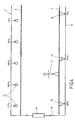
- FIG. 4 shows a large area luminaire 1 fastened to a ceiling (not shown), which essentially consist of lamps arranged side by side, here Fluorescent tubes 12 and a diffuser suspended below them in the form of a film 6 consists.
- the distance between the light sources 12 and their distance from the Diffusers are chosen so that by overlaying the individual illuminants 12 radiated brightness, a uniform illumination of the diffuser 6 is effected, without individual bulbs undesirably emerging.
- a Control / data line 18 includes the light sources 12 which can be influenced in terms of their brightness a central control unit 17 connected. This is the case with fluorescent tubes Dimming generally via electronic ballasts, which are not shown in FIG. 4 are drawn.
- the power supply to the light sources 12 is also not shown in FIG. 4 explicitly drawn.
- the control / data line 18 is optionally a point-to-point connection or bus executable, depending on the light sources used or Ballasts.
- the control unit 17 is also connected to sensors embedded in the floor, for example capacitive proximity switches. For aesthetic reasons, these can be hidden from viewer 2. Depending on how the sensors 15 work these, of course, also attached above the diffuser 6 or on the walls be attached. Via a further data line 19, connected as a point-to-point connection or as a bus, the signals from the sensors 15 to the central Control unit 17 transmitted.
- the position of person 2 is determined as follows: depending on the proximity of object 2, sensors 15 send a signal between 0 and 100%.
- sensors 15 send a signal between 0 and 100%.
- the central control unit 17 determines the from these values Presumed position of person 2, whereby instead of providing a sensor matrix one sensor line, two-dimensional position determinations are also possible.
- light sources 12 Brightness applied from left to right as follows: 31%, 100%, 100%. 30%, 5 %.
- FIGS. 1 to 3 Special applications and further details are shown in FIGS. 1 to 3 explained.
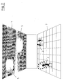
- FIG. 1 shows a large area luminaire 1 designed as a wall surface, behind which there is several invisible light sources, sensor elements and ballasts are located.
- the area of the existing people 2 is only in their immediate vicinity lighting is provided, which is characterized by the illuminated wall area 3 is, while existing in the end areas or in the intermediate area Light sources cannot be controlled.
- Figure 2 shows a similar arrangement, but it is a Large area light 4 acts, which is mounted on a ceiling and the one below illuminates the room. Only where people 2 are present individual islands of light 5, which are indicated by brightly lit circles, during the remaining area is not illuminated.
- the unrecognizable sensors can For example, be arranged behind a diffuser 6 or in the bottom 7.
- FIG. 3 shows a diffuser 10, for example a, in a sectional side view Translucent film in front of a lighting device 11 consisting of light sources 12, for example fluorescent tubes, and ballasts 13.
- the Ballasts 13 are mounted with the light sources 12 on a support plate 14 can in turn be attached to a wall or ceiling.
- a flat sensor 15 is arranged, with its Electric field 16 penetrates the diffuser 10 and the area in front of or below the diffuser 10 detected. In the event of a disorder caused by a person electromagnetic field 16, this is thus detected by the sensor 15, one Distance determination and the speed of the approaching person possible is.
- the control unit can use the necessary information is provided in order to control the individual Allow light sources 12.
- the control can, for example, be in a change but the color temperature preferably consists of a change in intensity.
Abstract
Description
Die Erfindung betrifft eine Beleuchtungsvorrichtung und ein Verfahren zum Beleuchten von Objekten mit mehreren ansteuerbaren Lichtquellen mit den Merkmalen des Oberbegriffs der unabhängigen Ansprüche.The invention relates to a lighting device and a method for lighting of objects with several controllable light sources with the characteristics of Preamble of the independent claims.
Beleuchtungseinrichtungen der gattungsgemäßen Art werden bevorzugt für abgehängte Decken und gegebenenfalls auch für Wände eingesetzt, wobei von Ausnahmen abgesehen, die Lichtquellen hinter einem Diffusor angeordnet werden. In der Regel handelt es sich hierbei um Großflächenleuchten, die als Wand- oder Deckenleuchten vollflächig ausgebildet sind und aus architektonischer Sicht neben der reinen Beleuchtungsfunktion ein räumliches Gestaltungselement darstellen. Anstelle von Großflächenleuchten können aber auch einzelne, verteilte und miteinander kombinierte Diffusorelemente zur Ausleuchtung oder aber einzelne im Raum verteilte Beleuchtungskörper verwendet werden. Somit werden dem Architekten Optionen für eine Lichtplanung ohne sichtbare Lichtquellen angeboten, die sich wesentlich vom Erscheinungsbild gegenüber herkömmlichen Beleuchtungssystemen abheben und der planerischen Gestaltung durch den Architekten freien Raum geben. Die Beleuchtungseinrichtungen können hierbei mit Lichtquellen in unterschiedlichen Farben ausgestattet sein und ermöglichen durch komplexe Steuerungen jedes einzelnen Vorschaltgerätes differenzierte Beleuchtungssituationen künstlerisch in Szene zu setzen, wobei für den Betrachter durch die nicht erkennbaren Lichtquellen und der Verwendung eines Diffusors angenehme Farbvarianten erzeugt werden, die in Verbindung mit beispielsweise akustischen Wiedergaben bestimmte Stimmungseffekte hervorrufen. Hierbei werden in der Regel Lichtquellen mit den drei Grundfarben eingesetzt, die durch unterschiedliche Intensitäten der drei Grundfarben ein frei wählbares und individuelles Farbspektrum entstehen lassen.Lighting devices of the generic type are preferred for suspended ceilings and possibly also used for walls, whereby from Apart from exceptions, the light sources are arranged behind a diffuser. In As a rule, these are large area luminaires that can be used as wall or Ceiling lights are fully formed and from an architectural point of view next to the pure lighting function represent a spatial design element. Instead of Large area luminaires can also be single, distributed and together Combined diffuser elements for illumination or individual ones distributed in the room Lighting fixtures can be used. This gives the architect options for light planning without visible light sources is offered, which differs significantly from Stand out from conventional lighting systems and the give the architect design freedom. The lighting devices can be used with light sources in different colors be equipped and enable each one with complex controls Artistically staging differentiated lighting situations, for the viewer due to the unrecognizable light sources and the use of a diffuser pleasant color variations are generated, which in connection with for example, acoustic reproductions cause certain mood effects. Usually light sources with the three primary colors are used different intensities of the three basic colors a freely selectable and individual Let the color spectrum emerge.
Die Betrachter oder Besucher derartig gestalteter Räume empfinden ein völlig anderes Verhältnis zum Licht, da die Lichtquellen und damit die Ursache für eine hervorgerufene Stimmung nicht direkt erkennbar sind. Ohne erkennbare Anhaltspunkte für die technischen Einrichtungen oder für eine direkte Zuordnung der Lichteffekte ist es daher wesentlich einfacher, die Stimmung wirken zu lassen. Im Idealfall wirken solch gestaltete Lichtszenen überhaupt nicht als Beleuchtungselement, sondern eher als ein natürliches Oberlicht oder eine Lichtkuppel, wobei ein als natürlich empfundenes Licht in der Regel als besonders angenehm empfunden wird. Durch aufwendige Steuerungseinrichtungen können hierbei stimmungsvolle Lichtübergänge oder Farben gewählt werden, die zweckentsprechend ausgewählt werden.The viewers or visitors of rooms designed in this way experience a completely different feeling Relationship to light, since the light sources and thus the cause of an evoked Mood is not immediately recognizable. With no discernible clues to the technical equipment or for a direct assignment of the lighting effects it is therefore much easier to let the mood work. Ideally, such designed ones work Light scenes not at all as a lighting element, but rather as a natural one Skylight or a skylight dome, with a light normally perceived as natural is perceived as particularly pleasant. Through elaborate control devices Atmospheric light transitions or colors can be selected be selected appropriately.
Zur Lichtsteuerung sind hierbei Bewegungsmelder oder Präsenzmelder bekannt, die mit Ultraschall- oder Infrarotsensoren arbeiten und in einem einstellbaren Erfassungswinkel jede Bewegung wahrnehmen oder Wärmestrahlung erfassen und die Einschaltung einer Lichtquelle vornehmen. Derartige Bewegungsmeider haben sich jedoch speziell für Großflächenleuchten nicht bewährt oder stören die vorhandene architektonische Geometrie, da sie wie Sprenkler oder Rauchmelder stets zu den Personen hin durch Decken oder Wände hindurch geführt werden müssen und somit für jedermann frei einsehbar sind. Infrarotsensoren können zudem nicht versteckt in Lichtdecken mit Leuchtstofflampen eingesetzt werden, weil die Wärme erzeugenden Vorschaltgeräte oder Leuchtstofflampen insbesondere wegen Rückreflektionen die Einschaltvorgänge beeinflussen und möglicherweise für Dauerlicht sorgen. Ein Einsatz ist aber dort möglich, wo sie nicht in Richtung der Beleuchtung blicken.For light control, motion detectors or presence detectors are known which are associated with Ultrasonic or infrared sensors work and in an adjustable detection angle perceive every movement or heat radiation and switch on one Make light source. Such movement avoiders have, however, especially for Large area luminaires have not proven their worth or interfere with the existing architectural Geometry, because like sprinklers or smoke detectors they always go through to the people Ceilings or walls must be led through and therefore free for everyone are visible. Infrared sensors can also not be hidden in illuminated ceilings Fluorescent lamps are used because the heat-generating ballasts or fluorescent lamps, particularly because of back reflections, the switch-on processes influence and possibly provide continuous light. However, it can be used there where they don't look towards the lighting.
Ferner hat sich gezeigt, dass auch im Bereich der Lichtdecken oder Großflächenleuchten nicht unbedingt der gesamte Raum ausgeleuchtet werden muss, sondern eine Teilausleuchtung völlig ausreichend ist. Festinstallierte Beleuchtungssituationen sind hier besonders hinderlich, da sie nur aufwendig von Technikern in ihrer Installation geändert werden können, sodass auf unpraktische Tischleuchten zurückgegriffen werden muss. Sowohl für festinstallierte Leuchtenkörper als für durchgehende Lichtdecken gilt, dass eine zentrale Lichtsteuerung die Flexibilität nur noch mehr einschränkt, da auch die Bedienungselemente bei jeder Änderung angepasst werden müssen. Insofern steht die bisherige Steuerungstechnik in flexiblen Großraumbüros aus einem starren durchgehenden Raster die Beleuchtungstechnik am einzelnen Arbeitsplatz praktisch nie optimiert sein kann. Durchgehende Lichtdecken sind zwar überall gleich gut für eine Beleuchtungstechnik einsetzbar, arbeiten jedoch besonders unwirtschaftlich, wobei die komplexe Steuerung auch nur selten der Flexibilität gerecht werden kann, sodass mit erheblichen Energieaufwand oft die ganze Decke beleuchtet ist, obwohl nur an wenigen Arbeitsplätzen Licht benötigt wird. It has also been shown that also in the area of luminous ceilings or Large area luminaires do not necessarily have to illuminate the entire room, partial illumination is sufficient. Permanently installed Lighting situations are particularly troublesome here, since they only require a lot of effort Technicians can be changed in their installation, making it impractical Table lamps must be used. Both for fixed luminaire bodies and for continuous luminous ceilings, central lighting control only provides flexibility is even more restrictive, since the controls also change every time need to be adjusted. In this respect, the previous control technology is flexible Open-plan offices from a rigid, continuous grid the lighting technology on individual workplace can never be optimized. Continuous luminous ceilings are can be used equally well for lighting technology everywhere, but they work particularly uneconomical, although the complex control is rarely the Flexibility can do justice, so that with considerable energy expenditure often the whole The ceiling is illuminated, although light is only required at a few workplaces.
Zur Energieersparnis bietet sich außerdem die Möglichkeit, an jedem Arbeitsplatz Bedienelemente vorzusehen, so dass die Lichtdecke nur in einem relativ kleinen Bereich rund um den Arbeitsplatz herum ausgeleuchtet wird. Dies erfordert jedoch eine gewisse Disziplin, da beim Verlassen und Betreten des Arbeitsplatzes das Bedienelement geschaltet werden muss. In langen Fluren ist diese Lösung nicht anwendbar, da während des Durchschreitens ständig Abschnitte an- und ausgeschaltet werden müssen. Nachteilig ist auch das technisch bedingte Rastermaß, welches die Beleuchtungssituationen im Raums vorgibtTo save energy, there is also the option of working at any place Provide controls so that the luminous ceiling is only in a relatively small area is illuminated around the workplace. However, this requires a certain amount Discipline because the control element when leaving and entering the workplace must be switched. This solution cannot be used in long corridors because sections are constantly switched on and off while walking through them have to. Another disadvantage is the technical grid dimension, which the Specifies lighting situations in the room
In langen Fluren und Unterführungen, beispielsweise in Flughäfen oder Hotelfluren, ist es weit verbreitet, Infrarot-Bewegungsmelder vorzusehen, die beim Durchschreiten des Flures mehr oder weniger lange Flurabschnitte beleuchten. Beim Betreten eines neuen Flurabschnitts gehen daher nachteilhafterweise die Lampen plötzlich und gut sichtbar für den Betrachter an, evtl. sogar mit Flackern. Entweder geht man "ins Dunkle" oder es werden unnötig viele Lampen zu früh angeschaltet bzw. zu spät ausgeschaltet. Grundsätzlich werden dabei auf einmal ganze Abschnitte gleichzeitig geschaltet. Ähnliches gilt für sensorgesteuerte Lampen, z. B. Gartenleuchten mit IR-Melder: Wenn man sich auf eine solche zu bewegt, schaltet sich die Lampe an und leuchtet damit plötzlich einen neuen Abschnitt aus.It is in long corridors and underpasses, for example in airports or hotel corridors widely used to provide infrared motion detectors, which when passing through the Illuminate corridors of more or less long corridors. When entering a new one Correspondingly, the lamps in the corridor section suddenly and clearly go out for the viewer, possibly even with flickering. Either you go "in the dark" or it unnecessarily many lamps are switched on too early or switched off too late. Basically, entire sections are switched at once. The same applies to sensor-controlled lamps, e.g. B. Garden lights with IR detector: If if you move towards one, the lamp turns on and lights up suddenly a new section.
Außerdem sind im Show-Bereich automatisch mitgeführte Scheinwerfer bekannt, die immer auf eine Person zentriert sind. Eine solche mechanisch Vorrichtung umfasst Verschleißteile und ist auch wegen des grellen Lichts, der räumlichen Anordnung und der Ausrichtung des Lichts nicht für die zuvor genannten Anwendungen geeignet.In addition, automatically carried headlights are known in the show area are always centered on one person. Such a mechanical device comprises Wear parts and is also because of the glaring light, the spatial arrangement and the direction of the light is not suitable for the aforementioned applications.
Der Erfindung liegt daher die Aufgabe zugrunde, eine gegenüber der bekannten Steuerungstechnik verbesserte Beleuchtungssteuerung aufzuzeigen, die eine partielle, unbewusste Beeinflussung der Ausleuchtung durch einen Betrachter oder Besucher ermöglicht.The invention is therefore based on the object, one compared to the known Control technology to show improved lighting control, which is a partial, unconsciously influencing the illumination by a viewer or visitor allows.
Diese Aufgabe wird gelöst durch ein Verfahren bzw. eine Beleuchtungseinrichtung nach den unabhängigen Ansprüchen. Vorteilhafte Ausgestaltungen sind Gegenstand der Unteransprüche. This object is achieved by a method or an illumination device according to the independent claims. Advantageous refinements are the subject of Dependent claims.
Beim erfindungsgemäßen Verfahren ist vorgesehen, dass Sensoren zunächst ein Objekt, beispielsweise einen Besucher, erfassen, dann die genaue Position des Objekts bestimmt wird und schließlich die Steuerungseinheit so angesteuert wird, dass die Beleuchtungseinrichtung dort eine größere oder die maximale Helligkeit ausweist, wo die Position des Objekts ist. Darunter kann auch eine Bereich um das Objekt herum verstanden werden. Dabei kann jede Art eines Sensors verwendet werden, der in der Lage ist, eine Person oder einen Gegenstand zu erfassen. Je nach Anwendungsgebiet und der zu erfassenden Objekte kommen Ultraschallsensoren, Infrarot-Bewegungsmelder, kapazitive Näherungsschalter und dergleichen in Frage. Zur Umsetzung der Erfindung kommt es nicht auf einen speziellen Sensor an. Genauso gut sind Drucksensoren oder die Auswertung von Kamera- bzw. Infrarot-Bildern denkbar. Ein Objekt kann beispielsweise dadurch entdeckt werden, dass seine Geschwindigkeit ausgewertet wird, oder eine wie auch immer geartete Veränderung der Umgebung. Die Position des Objekts kann durch einen Sensor, beispielsweise Kamera, oder eine Vielzahl von Sensoren, beispielsweise mehrere kapazitive Näherungsschalter zusammen mit einer entsprechenden Elektronik zur Auswertung der von den Sensoren stammenden Signalen, erfolgen. Die Position des Objekts kann ein-, zwei- oder dreidimensional bestimmt werden. Eine eindimensionale Bestimmung liegt beispielsweise vor in Gängen und Fluren, bei denen das Licht nur in Flurrichtung mitgeführt werden kann. Eine zweidimensionale Positionsbestimmung ist zweckmäßig in großen Hallen oder Großraumbüros, bei denen sogenannte Lichtinseln um das Objekt herum gebildet werden können. Schließlich ist auch eine dreidimensionale Positionsbestimmung denkbar, bei der auch die Höhe des Objekts, beispielsweise im Fahrstuhl oder auf der Treppe, berücksichtigt wird. Unter die Erfindung fallen auch andere Mittel zur Positionsbestimmung der Objekte, z. B. Sender oder Transponder, die das Objekt mit sich führt.In the method according to the invention it is provided that sensors first an object, a visitor, for example, then the exact position of the object is determined and finally the control unit is controlled so that the Lighting device shows a greater or the maximum brightness where is the position of the object. This can include an area around the object be understood. Any type of sensor can be used, which in the Is able to grasp a person or an object. Depending on the area of application and the objects to be detected are ultrasound sensors, infrared motion detectors, capacitive proximity switches and the like in question. to Implementation of the invention does not depend on a special sensor. As good as pressure sensors or the evaluation of camera or infrared images are conceivable. On Object can be discovered, for example, by its speed is evaluated, or any kind of change in the environment. The position of the object can be determined by a sensor, for example a camera, or a Large number of sensors, for example several capacitive proximity switches together with appropriate electronics for evaluating those from the sensors Signals. The position of the object can be one, two or three-dimensional be determined. A one-dimensional determination exists, for example, in corridors and corridors where the light can only be carried in the direction of the corridor. A Two-dimensional positioning is useful in large halls or Open-plan offices in which so-called islands of light are formed around the property can be. Finally, there is also a three-dimensional position determination conceivable at which the height of the object, for example in the elevator or on the Stairs, is taken into account. The invention also includes other means of Position determination of the objects, e.g. B. transmitter or transponder that the object with leads.
Das Verfahren ist besonders gut umsetzbar mit einer Vielzahl von handelsüblichen Sensoren, die jeweils einzeln einen Messwert liefern, der in einer bekannten Relation zur Entfernung bzw. Geschwindigkeit des registrierten Objekts stehen kann. Die mit den Sensoren verbundene Steuerung kann daher aus den von einer Vielzahl von Sensoren gelieferten Signalen Rückschlüsse auf die Position des Objekts ziehen und die Lichtquellen so ansteuern, das sich über oder in einem Bereich um das Objekt eine höhere Helligkeit ergibt. Zur Positionsbestimmung ist außerdem die Registrierung der Geschwindigkeit geeignet, da diese die erste Ableitung des Weges ist. Mehrere Sensoren haben den Vorteil, dass handelsübliche, preiswerte Sensoren eingesetzt werden können.The method can be implemented particularly well with a large number of commercially available ones Sensors, each of which individually delivers a measured value, which is in a known relation to the Distance or speed of the registered object can be. The one with the Controls connected to sensors can therefore be made up of a variety of sensors delivered signals draw conclusions about the position of the object and the Activate light sources in such a way that one over or in an area around the object results in higher brightness. The registration of the Suitable speed because this is the first derivative of the path. Several Sensors have the advantage that commercially available, inexpensive sensors are used can be.
Im Gegensatz zum Stand der Technik geschieht das Mitführen des Lichts mit dem Objekt energiesparend mit lokal auftretender Beleuchtung ohne Stufen, wie z. B. in Tiefgaragen und Hotelfluren, bei denen beim Betreten eines Flurabschnitts die Beleuchtung eines ganzen Abschnittes schlagartig angeht. Erfindungsgemäß kommt es vielmehr darauf an, dass die Beleuchtung quasi wie eine "Aura" oder "Lichtinsel" mit dem Objekt stufenlos fließend mitwandert. Dies wird insbesondere dadurch erreicht, dass die in Bewegungsrichtung liegenden Lichtquellen stufenlos heller und die in entgegengesetzter Richtung liegenden Lichtquellen stufenlos dunkler geregelt werden. Die Überlagerung des von den einzelnen Lichtquellen ausgestrahlten Lichts ergibt somit eine stufenlos mitwandernde "Lichtinsel", insbesondere bei Verwendung eines die einzelnen Lichtquellen verdeckenden Diffusors. Je nach Geometrie der Beleuchtungseinrichtung ist auch das Dimmen in Stufen möglich, wobei es darauf ankommt, dass die Stufen vom Auge nicht bewusst wahrgenommen werden.In contrast to the prior art, the light is carried along with the Object saves energy with local lighting without steps, such as B. in Underground garages and hotel corridors, in which the Illumination of an entire section suddenly started. According to the invention it comes Rather, it means that the lighting is more or less like an "aura" or "island of light" moves seamlessly with the object. This is achieved in particular by that the light sources in the direction of movement are continuously brighter and those in opposite light sources can be regulated continuously darker. The superimposition of the light emitted by the individual light sources thus results a continuously moving "island of light", especially when using a individual light sources covering diffuser. Depending on the geometry of the Lighting device is also possible to dim in stages, taking care of it arrives that the stages are not consciously perceived by the eye.
Für den Betrachter besonders angenehm ist diese Beleuchtung, wenn das Licht im näheren Umkreis vom Betrachter besonders hell ist und mit der Entfernung langsam abnimmt. Es ist im Allgemeinen nicht zwingend notwendig, dass im Bereich des erfassten Betrachters exakt die stärkste Helligkeit oder das genaue Zentrum der Lichtinsel vorliegt oder diese gleichmäßig mit zunehmender Entfernung in ihrer Helligkeit abnimmt. Der Helligkeitsgradient, der Helligkeitsmittelpunkt und die Helligkeit der entfernt liegenden Umgebung des Objekts sind daher in Abhängigkeit vom konkreten Anwendungsfall auszuwählen. Als besonders angenehm wird die Beleuchtung jedoch dann empfunden, wenn die Übergänge möglichst stufenlos sind.This lighting is particularly pleasant for the viewer when the light in the closer range from the viewer is particularly bright and slow with distance decreases. It is generally not absolutely necessary that in the area of precisely the highest brightness or the exact center of the light island is present or its brightness increases with increasing distance decreases. The brightness gradient, the brightness center and the brightness of the removed lying environment of the object are therefore dependent on the concrete Select use case. However, the lighting is particularly pleasant then felt when the transitions are as smooth as possible.
Das Verfahren ist dann mit preiswerter Technik zu realisieren, wenn nicht permanent, sondern in gewissen Zeitabständen, die Position des Objekts neu bestimmt wird. Dadurch ergibt sich eine gewisse Trägheit der Nachführung, die auch als gestalterisches Element eingesetzt werden kann. Wenn die Position des Objektes in einem Zeitintervall eine große Veränderung erfahren hat, dann sollte sich auch die Lichtinsel im einem bestimmten Verhältnis zum Zeitintervall und der Strecke schnell bewegen. The process can then be implemented using inexpensive technology, if not permanently, but at certain intervals, the position of the object is redetermined. This results in a certain sluggishness of the tracking, which is also a creative one Element can be used. If the position of the object in a time interval has undergone a major change, then the island of light should be in one move quickly in relation to the time interval and the distance.
Bevorzugt ist es bei der Form, Größe, Helligkeit oder Farbe der Leuchtinsel die Umgebungshelligkeit zu berücksichtigen. Dies hat die folgenden beispielhaft aufgeführten Vorteile: Nachts kommt beispielsweise eine Unterführung mit weniger Helligkeit aus, da die Augen an die Dunkelheit angepasst sind. Ja nach Beleuchtungssituation draußen, wie z. B. Bewölkung, Sonne, Tageszeit herrscht draußen ein bestimmter Farbton vor, der nachzubilden ist. Auch kann ähnlich wie bei Tunneln der Eintritt bzw. Austritt aus der erfindungsgemäßen Beleuchtungsvorrichtung an die Helligkeit der Ungebung angepasst sein, während im Zentralbereich der Beleuchtungsvorrichtung immer ein bestimmter Helligkeitswert vorherrscht. Die Helligkeit von Ein- und Austritt kann dabei natürlich auch unterschiedlich sein. Dabei versteht sich, dass das Licht mit dem beweglichen Objekt mitgeführt wird.It is preferred for the shape, size, brightness or color of the light island Ambient brightness. This has the following examples Advantages listed: At night, for example, there is an underpass with less Brightness off because the eyes are adjusted to the dark. Yes after Lighting situation outside, such as B. Clouds, sun, time of day prevails outside a certain shade that is to be reproduced. Also similar to tunnels Entry or exit from the lighting device according to the invention to the Brightness to be adjusted to the environment, while in the central area of the Lighting device always prevails a certain brightness value. The brightness of course, entry and exit can also be different. It goes without saying that the light is carried along with the moving object.
Die Beleuchtungseinrichtungen, die nach den zuvor erläuterten Verfahren betrieben werden können, weisen naturgemäß die zuvor genannten Vorteile gegenüber dem Stand der Technik auf.The lighting devices operated according to the previously explained methods can, of course, have the aforementioned advantages over the State of the art.
Insbesondere kommt es bei dieser Beleuchtungseinrichtung darauf an, dass eine im Bereich des Objekts wirkende Leuchtzone ("Lichtinsel") erzeugt werden kann, die insbesondere stufenlos, d. h. ohne plötzliche, bewusst wahrnehmbare Helligkeitsschwankungen mit dem Objekt mitführbar ist.In particular, it is important with this lighting device that an im Area of the object acting lighting zone ("light island") can be generated in particular continuously, d. H. without sudden, consciously perceptible Variations in brightness can be carried with the object.
Wenn jeder Lichtquelle genau ein Sensor zugeordnet ist, wobei die Helligkeit der Lichtquelle in Abhängigkeit der Entfernung zum Objekt steuerbar ist, kann die Leuchte modular und mit geringem Aufwand hergestellt werden, wobei nachträgliche Erweiterungen problemlos möglich sind, da nicht in die bestehende Einrichtung eingegriffen werden muss. Die einzelnen Lichtquellen bzw. Sensoren sind unabhängig voneinander, d. h. sie tauschen keine Daten aus. Die erfindungsgemäße Leuchte wird also in diesem Fall durch mehrere unabhängige Lampen mit Näherungssensor gebildet, bei denen die Lampen umso heller werden, je näher das Objekt bei ihr steht.If exactly one sensor is assigned to each light source, the brightness of the The light can be controlled depending on the distance to the object can be manufactured modularly and with little effort, with subsequent Extensions are possible without any problems since they are not in the existing facility must be intervened. The individual light sources or sensors are independent from each other, d. H. they do not exchange data. The lamp according to the invention is in this case by several independent lamps with proximity sensors formed, in which the lamps become brighter the closer the object is to her.
In einer vorteilhaften Ausgestaltung kann dieser Effekt für mehrere Objekte unabhängig voneinander bewirkt werden, was beispielsweise in Großraumbüros wichtig ist. In an advantageous embodiment, this effect can be independent for several objects from each other, which is important in open-plan offices, for example.
Leuchtstoffröhren, insbesondere solche, die über elektronische Vorschaltgeräte (EVG) betrieben werden, sind im Vergleich zu Glühlampen sparsamer im Verbrauch. Elektronische Vorschaltgeräte haben den Vorteil, dass die Leuchtstoffröhren flackerfrei und dimmbar betrieben werden können und beim Anlaufen nicht flackern. Das gleiche gilt für LEDs.Fluorescent tubes, in particular those that have electronic ballasts (EVG) are more economical to use than incandescent lamps. Electronic ballasts have the advantage that the fluorescent tubes flicker-free and can be operated dimmable and do not flicker when starting up. The same applies to LEDs.
Prinzipiell ist die erfindungsgemäße Vorrichtung auch mit nicht-dimmbaren Lichtquellen denkbar, sofern genügend von ihnen vorhanden sind, z. B. LEDs. Das Ein- oder Ausschalten einer einzelnen Lichtquelle wird in diesem Fall vom Betrachter nicht bewusst wahrgenommen, ähnlich wie bei den Pixeln eines Bildschirms. Dimmbare Lichtquellen sind jedoch bevorzugt, da dadurch die Anzahl der benötigten Lichtquellen sinkt.In principle, the device according to the invention is also with non-dimmable light sources conceivable, provided there are enough of them, e.g. B. LEDs. The one or In this case, the viewer is not aware of switching off a single light source perceived, similar to the pixels of a screen. Dimmable light sources are preferred, however, since this reduces the number of light sources required.
In einer Ausgestaltung ist vorgesehen, dass die Steuerungseinheit mit nicht sichtbar angeordneten Sensoren zusammenarbeitet, die beispielsweise eine elektromagnetische Feldänderung und somit eine Bewegung innerhalb eines auszuleuchtenden Bereiches erfassen und ein Steuersignal erzeugen, welches zur Ansteuerung einer oder mehrerer Lichtquellen vorgesehen ist. Durch die Verwendung nicht sichtbarer Sensoren wird die architektonische Gestaltung der Räume in keiner Weise beeinträchtigt und daher kommt eine solche Steuerung besonders für Großflächenleuchten infrage, bei denen eine architektonisch ansprechende Formensprache zum Ausdruck kommen soll, ohne dass diese durch Installation von kleinteiligen Beleuchtungselementen oder Bewegungsmelder das Gesamtkonzept zerstören. Erfindungsgemäß werden die Sensoren so angeordnet, dass sie für den Besucher völlig unsichtbar bleiben und der Besucher zunächst gar nicht merkt, dass er über Sensoren eine Beeinflussung der Lichtgestaltung vornimmt. Diese Beeinflussung kann neben in einer Intensitätsveränderung auch in einer Farbveränderung des ausgestrahlten Lichtes bestehen und sich auf kleinere oder größere Bereiche erstrecken. Diese Ausleuchtung ist jedoch nur im Zusammenhang mit einer Steuerungseinheit möglich, die eine Einzelansteuerung der Lichtquellen beziehungsweise Vorschaltgeräte ermöglicht. Durch die verwendeten Sensoren kann hierbei auf das Farbspektrum und auf die Lichtintensität Einfluss genommen werden, wobei in der Regel eine große Zahl von Sensoren für eine Großflächen leuchte eingesetzt wird, damit einzelne Lichtinseln individuell steuerbar sind, um beispielsweise nur die Lichtquellen im Erfassungsbereich eines einzelnen Sensors anzusteuern. Hierbei besteht die Möglichkeit, dass einzelne oder mehrere Lichtquellen durch mehrere Sensoren gesteuert werden und beispielsweise das Licht einer sich bewegenden Person folgt.One embodiment provides that the control unit is not visible arranged sensors cooperates, for example, a electromagnetic field change and thus a movement within a Detect area to be illuminated and generate a control signal, which for Control of one or more light sources is provided. By using it The architectural design of the rooms will not become invisible sensors Impaired and therefore such control comes especially for Large area luminaires in question, where an architecturally appealing Design language should be expressed without this by installing small-scale lighting elements or motion detectors the overall concept to destroy. According to the invention, the sensors are arranged so that they are for the Visitors remain completely invisible and the visitor does not even notice that he is influences the lighting design via sensors. This influencing can in addition to a change in intensity in a change in color of the emitted light exist and extend to smaller or larger areas. However, this illumination is only in connection with a control unit possible, the individual control of the light sources or ballasts allows. Due to the sensors used, the color spectrum and the light intensity can be influenced, usually a large number is used by sensors for a large area luminaire, so that individual islands of light are individually controllable, for example only the light sources in the detection area control of a single sensor. There is a possibility that individual or multiple light sources can be controlled by multiple sensors and for example that Light follows a moving person.
Ferner besteht die Möglichkeit, dass beispielsweise auf Bahnhöfen oder Flughäfen, große Räume, lange Flure oder Gänge mit einem Dämmerlicht ausgeleuchtet werden und erst beim Betreten voll oder zumindest teilweise mit hoher Lichtintensität ausgeleuchtet werden. Hierdurch lässt sich der Stromverbrauch in erheblicher Weise reduzieren.There is also the possibility that, for example, at train stations or airports, large rooms, long corridors or corridors are illuminated with dim light and only when you enter it fully or at least partially with high light intensity be illuminated. This allows the power consumption to be significantly increased to reduce.
Besonders vorteilhaft ist die Kombination der Sensoren in Verbindung mit einer als Diffusor ausgebildeten Folie, insbesondere transluzenten Folie oder einer Lackfolie. Hierbei können die Lichtquellen zur Erreichung einer gleichmäßig ausgeleuchteten Fläche hinter dem Diffusor angeordnet sein oder als Spots, beispielsweise in der Lackdecke oder Lackfolie, integriert sein. Somit sind die Sensoren unsichtbar hinter der Folie beziehungsweise Lackdecke angeordnet und ermöglichen eine individuelle partielle Lichtsteuerung, ohne das ein Betrachter die Steuerungselemente erkennen kann und darüber hinaus die Beeinflussung durch ihn selbst zunächst erkennt. Die Sensoren können aber auch in einzelnen Beleuchtungskörpern eingesetzt werden, die verdeckt liegende Sensoren insbesondere mit einem Erfassungsbereich von 360° enthalten.The combination of the sensors in connection with an as is particularly advantageous Diffuser-formed film, in particular translucent film or a lacquer film. Here, the light sources can be used to achieve a uniformly illuminated Be arranged behind the diffuser or as spots, for example in the Paint ceiling or paint film, be integrated. The sensors are therefore invisible behind the Foil or lacquer ceiling arranged and allow an individual partial light control without an observer recognizing the control elements can and also first recognizes the influence by himself. The However, sensors can also be used in individual lighting fixtures hidden sensors, in particular with a detection range of 360 ° contain.
Alternativ besteht die Möglichkeit, dass die Sensoren hinter einer als Diffusor ausgebildeten mattierten Glas- oder Kunststoffscheibe angeordnet werden und die Lichtquellen entsprechend der Ausführung mit einer Folie hinter dem Diffusor angeordnet sind. Mattierte Glas- oder Kunststoffscheiben sorgen ebenso wie eine transluzente Folie für eine optimale Streuung des Lichtes, sodass eine gleichmäßige schattenfreie Ausleuchtung erfolgt.Alternatively there is the possibility that the sensors are behind a diffuser trained frosted glass or plastic pane can be arranged and the Light sources according to the version with a film behind the diffuser are arranged. Frosted glass or plastic panes provide just as much as one translucent film for optimal light scattering, so that an even shadow-free illumination takes place.
In besonderer Ausgestaltung der Erfindung ist vorgesehen, dass die Sensoren als Sensorfeldmatrix ausgebildet z. B. in dem Diffusor, beispielsweise der mattierten Glasoder Kunststoffscheibe, integriert sind oder unsichtbar auf der Innen- oder Außenseite befestigt sind, Hierzu wird vorzugsweise ein transparentes Sensormaterial wie Indiumzinnoxid eingesetzt, welches hochtransparent ist und in keiner Weise die Lichtwirkung nachteilig beeinflusst. Durch die Sensorfeldmatrix wird aber auch unter Berücksichtigung des Erfindungsgegenstandes ein besonders großes Erfassungsfeld geschaffen, wodurch eine teilweise Ausleuchtung des Raumes vorgenommen werden kann.In a special embodiment of the invention it is provided that the sensors as Sensor field matrix formed z. B. in the diffuser, for example the frosted glass or Plastic pane, integrated or invisible on the inside or outside are attached, a transparent sensor material such as Indium tin oxide is used, which is highly transparent and in no way the Illumination adversely affected. Through the sensor field matrix is also under Consideration of the subject of the invention a particularly large field of coverage created, which partially illuminates the room can.
Sensoren mit großer Reichweite erhält man durch große Flächen, z. B. eine auf einer Fensterscheibe aufgebrachte elektrisch leitfähige Schicht, beispielsweise Sonnenschutzschicht oder Wärmeschutzschicht. Diese können dann auch als Elektrode bei einem kapazitiven Annäherungsschalter genutzt werden. Dadurch können extrem große Elektroden gebildet werden, wodurch der Näherungsschalter eine besonders hohe Reichweite hat.Long-range sensors are obtained from large areas, e.g. B. one on one Window pane applied electrically conductive layer, for example Sun protection layer or heat protection layer. These can then also can be used as an electrode in a capacitive proximity switch. As a result, extremely large electrodes can be formed, whereby the Proximity switch has a particularly long range.
In besonderer Ausgestaltung der Erfindung ist vorgesehen, dass die Sensoren die Annäherung sowie die Geschwindigkeit und Entfernung der sich nähernden Objekte beziehungsweise Personen erfassen, sodass beispielsweise in Abhängigkeit der Entfernung die Intensität der Lichtquellen zu- oder abnimmt oder die Farbtemperatur verändert wird. Durch die zusätzliche Erfassung der Geschwindigkeit der Bewegung kann ebenfalls die Intensität oder die Farbtemperatur beeinflusst werden.In a special embodiment of the invention it is provided that the sensors Approach as well as the speed and distance of the approaching objects or people, so that depending on the Distance the intensity of the light sources increases or decreases or the color temperature is changed. By additionally capturing the speed of the movement the intensity or the color temperature can also be influenced.
Die Information über die Geschwindigkeit des Objekt, die natürlich auch mittelbar durch die zeitliche Veränderung der Position ermittelt werden kann, kann beispielsweise auch benutzt werden, um die Größe, Form, Helligkeit oder Farbe der Lichtinsel zu beeinflussen, wie die folgenden Beispiele zeigen: Bei schnell bewegten Objekten kann die Lichtinsel vergrößert sein, um das Objekt nicht "ins Dunkle" laufen zu lassen. Es ist ferner denkbar, die Lichtinsel so zu formen, dass sie eine gestreckte Form in Richtung der Bewegung des Objekts erhält und nach vorne eine größere Fläche und nach hinten eine kleinere Fläche abdeckt. Wer langsam ein Gebiet durchschreitet und dabei Details des Gebiets wahrnehmen möchte, z. B. bei der Qualitätskontrolle, benötigt mehr Licht, als jemand, der nur zügig das Gebiet passiert.The information about the speed of the object, of course, also indirectly the change in position over time can also be determined, for example used to change the size, shape, brightness or color of the light island influence, as the following examples show: With fast moving objects the island of light must be enlarged so that the object does not run "in the dark". It is it is also conceivable to shape the light island so that it has an elongated shape in the direction the movement of the object receives a larger area to the front and to the rear covers a smaller area. Whoever walks slowly through an area and details want to perceive the area, e.g. B. in quality control, needs more light, as someone who passes the area quickly.
Die hierzu einsetzbaren Sensoren bestehen beispielsweise aus kapazitiven Nährungsschaltern großer Reichweite, die auch über große Entfernungen die Annäherung eines Besuchers wahrnehmen und somit über mehrere Stufen hinweg Steuersignale entsprechend der Entfernung oder Art der Bewegung erzeugen, die in eine Intensitäts- beziehungsweise Farbtemperatursteuerung umgesetzt werden. Das in der kapazitiven Schaltungstechnik verwendete elektromagnetische Feld durchdringt hierbei den Diffusor beziehungsweise die Lackfolie und wertet die Situation vor der Beleuchtungseinrichtung aus. Alternativ besteht die Möglichkeit, dass die Sensoren beispielsweise in den Boden vor einer Lichtwand beziehungsweise unter einer Lichtdecke integriert werden und beim Betreten beziehungsweise Durchschreiten des Raumes eine Lichtbeeinflussung ermöglichen. So kann beispielsweise ein Tunnel durch seitliche Lichtwände oder Lichtdecken hergestellt und eine Beleuchtungssituation geschaffen werden, die genau in dem Bereich die Lichtquellen beaufschlagt, in dem sich der Besucher gerade aufhält. Gegenüber einer herkömmlichen festinstallierten Beleuchtung aus vielen einzelnen Einzelleuchten, die eine optimale Beleuchtungssituation nur in ihrer unmittelbaren Nähe erzeugen, kann somit die vorgesehene Beleuchtung mit Hilfe der Sensortechnik stets mit dem Gast mitwandern und ihn beim Durchschreiten des Raumes oder des Tunnels begleiten. Das hierdurch beispielsweise der Energieverbrauch reduziert werden kann, da immer nur die Leuchten angesprochen werden, die tatsächlich benötigt werden, ist nahezu selbstverständlich und führt darüber hinaus auch zu interessanten Effekten, die einen bleibenden Eindruck hinterlassen. Daher eignen sich derartige Großflächenleuchten unter anderem auch in repräsentativen Räumen oder für Werbemaßnahmen. Soweit notwendig können alle auszuleuchtenden Räume ein notwendiges Dämmerlicht aufweisen, um einen Besucher die Tiefe des Raumes ansatzweise zu verdeutlichen,The sensors that can be used for this purpose consist, for example, of capacitive sensors Proximity switches with a long range, which can also be used over long distances Perceive a visitor's approach and thus over several levels Generate control signals according to the distance or type of movement that are in an intensity or color temperature control can be implemented. This in of the capacitive circuit technology penetrates the electromagnetic field the diffuser or the paint film and evaluates the situation before Lighting device off. Alternatively there is the possibility that the sensors for example in the floor in front of a light wall or under one Luminous ceiling are integrated and when entering or walking through the Allow space to be influenced by light. For example, a tunnel can go through Lateral light walls or luminous ceilings are produced and a lighting situation be created, which acts exactly on the light sources in the area in which the visitor is staying. Compared to a conventional fixed installation Lighting from many individual luminaires that are optimal The lighting situation can only generate in its immediate vicinity Always use the sensor technology to walk the intended lighting with the guest and accompany him as he walks through the room or the tunnel. This way For example, energy consumption can be reduced because only the lights are used addressed, which are actually needed, is almost a matter of course and also leads to interesting effects that leave a lasting impression leave. Such large area luminaires are therefore also suitable in representative rooms or for advertising. If necessary, everyone can rooms to be illuminated have a necessary dim light in order to To make the depth of the room clear to visitors,
Ein weiterer wesentlicher Vorteil der vorgestellten Technik eröffnet sich beispielsweise auch beim Einsatz der Lichtdecken in einem Großraumbüro, in dem mehrere Arbeitsplätze vorhanden sind und beispielsweise nur einzelne zurzeit besetzt sind. Hier besteht die Möglichkeit über die Sensoren die Anwesenheit einer Person zu erfassen und im unmittelbaren Umfeld des Arbeitsplatzes für eine optimale Beleuchtung zu sorgen, während hingegen der übrige Raum, und zwar dort wo sich keine Personen aufhalten, abgedunkelt ist. Hierdurch kann die betreffende Person wesentlich konzentrierter arbeiten und fühlt sich nicht durch andere Lichtquellen gestört, wobei nebenbei der Energieverbrauch erheblich reduziert wird. Hinzu kommen die besonderen Vorteile der Lichtdecken die ein völlig diffuses Licht und eine homogene Lichtverteilung ohne Blendwirkung und störende Reflexe auf Bildschirmoberflächen verursachen und eine schattenfreie Ausleuchtung der Arbeitsfläche beziehungsweise des Arbeitsbereiches ohne störende Leuchtkörper ermöglichen, Diese Variante bietet sich insbesondere in Großraumbüros an, wo eine flexible Gestaltung der einzelnen Arbeitszonen im Vordergrund steht und jederzeit ein leichtes Verändern der Arbeitsplatzsituation oder Bildung von Arbeitsgruppen durch Trennwände oder Schaffung von weiteren Arbeitsplätzen gefordert wird. Mit Hilfe der Sensoren kann die Anwesenheit von Personen unterhalb der Lichtdecke festgestellt werden, sodass einzelne Gruppen von Lichtquellen, beispielsweise Leuchtstoffröhren im Umfeld eines Sensors eingeschaltet werden und ermöglichen unter anderem eine Absenkung des Energieverbrauchs. Im Extremfall kann das Licht einem einzelnen Mitarbeiter in einem Großraumbüro stets an den Arbeitsplatz folgen, an dem er sich gerade aufhält. Bei voller Besetzung des Großraumbüros leuchtet selbstverständlich die ganze Decke, sodass an jedem Platz, an dem sich ein Mitarbeiter derzeit befindet personenabhängig ideale Lichtverhältnisse entstehen.Another significant advantage of the technology presented opens up, for example also when using the luminous ceilings in an open-plan office in which several Jobs are available and, for example, only a few are currently occupied. Here it is possible to detect the presence of a person via the sensors and to ensure optimal lighting in the immediate vicinity of the workplace, while the rest of the room, where no one is, is darkened. As a result, the person in question can be much more concentrated work and does not feel disturbed by other light sources Energy consumption is significantly reduced. Added to this are the special advantages of Luminous ceilings with a completely diffuse light and a homogeneous light distribution Cause glare and distracting reflections on screen surfaces and a shadow-free illumination of the work surface or the work area Allow without annoying illuminants, This variant is particularly useful in Open-plan offices where a flexible design of the individual work zones in the The foreground is and at any time a slight change in the workplace situation or Formation of working groups through partitions or creation of further ones Jobs is required. With the help of sensors, the presence of people below the light ceiling, so that individual groups of Light sources, for example fluorescent tubes in the vicinity of a sensor, are switched on among other things and enable a reduction in energy consumption. in the In extreme cases, the light can always be on a single employee in an open-plan office follow the workplace where he is currently. When the Of course, open-plan offices light up the entire ceiling, so that in every place an employee is currently in ideal lighting conditions depending on the person arise.
In weiterer Ausgestaltung der Erfindung ist vorgesehen, dass die Sensoren mit einem tageslichtabhängigen Sensorelement, beispielsweise einem Fotowiderstand oder einer Fotodiode, kombiniert eingesetzt werden, sodass unter Berücksichtigung der vorhandenen Lichthelligkeit eine Beeinflussung der Lichtquellen nur bei Dunkelheit oder im Dämmerlicht erfolgt. Darüber hinaus können Sensoren mit weiteren Steuerungselementen gekoppelt werden, die eine Beaufschlagung von einzelnen oder mehreren Lichtquellen unabhängig von den ansprechenden Sensoren ermöglichen, wenn dies gewünscht wird.In a further embodiment of the invention it is provided that the sensors with a daylight-dependent sensor element, for example a photo resistor or one Photodiode, can be used in combination, so that taking into account the existing light brightness an influence of the light sources only in the dark or done in dim light. In addition, sensors with other Control elements can be coupled, the application of individual or enable multiple light sources regardless of the responsive sensors, if so desired.
Die aufgezeigte Steuerungstechnik kann ferner auch zur Gestaltung bei künstlerischen Darbietung oder aber in Lichttherapieräumen eingesetzt werden, die völlig neue Behandlungsmethoden ermöglichen.The control technology shown can also be used to design artistic Performance or used in light therapy rooms, the completely new Enable treatment methods.
Die verwendeten kapazitiven Sensoren bestehen in der Regel aus einer Sensorplatte und können unsichtbar für jeden Betrachter beispielsweise hinter dem Diffusor oder einer Verkleidung montiert werden. Die Reichweite des homogenen elektrischen Feldes ist hierbei individuell einstellbar und kann bis zu einer Größe von mehreren Quadratmetern eingestellt werden. Neuartige Sensoren zeigen sich darüber hinaus durch eine hohe Störsicherheit durch digitale Filtertechnik aus und sind unempfindlich gegen Umwelteinflüsse unter anderem auch gegen Mobilfunk.The capacitive sensors used usually consist of a sensor plate and can be invisible to any viewer, for example, behind the diffuser or one Cladding can be installed. The range of the homogeneous electric field is individually adjustable and can be up to a size of several square meters can be set. Novel sensors are also shown by a high one Interference immunity through digital filter technology and are insensitive to Environmental influences including against mobile communications.
Die flachen Sensoren können somit unsichtbar für jeden Betrachter angeordnet werden und das elektrische Feld durchdringt alle nicht leitenden Materialien, wie Holz oder Kunststoff. Durch leitende oder schwach leitende Materialien wird das elektrische Feld abgelenkt, sodass vorhandene Gegenstände oder metallische Möbeleinrichtungen von diesem Feld eingehüllt werden und der Bereich vor und hinter den vorhandenen Möbeln zur Lichtbeeinflussung ebenfalls herangezogen werden kann. Zur Abschirmung gegenüber elektromagnetischer Strahlung der Vorschaltgeräte oder andere Geräte die zur Ansteuerung der Lichtquellen benötigt werden, kann hierbei eine Abschirmung verwendet werden, die zwischen diesen Geräten und dem Sensor angeordnet ist, wobei dieser hinter den einzelnen Lichtquellen liegend montiert wird, damit keine Schattenwirkung auch bei einer transluzenten Folie entsteht, Das elektrische Feld der Sensoren durchdringt hierbei ungehindert die Folie und erfasst den Bereich unterhalb der Decke oder vor einer Wandfläche. Zur Verstärkung des elektrischen Feldes beziehungsweise Erzeugung bestimmter Feldabmessungen können die Sensoren mit elektromagnetisch empfindlichen Flächen beispielsweise Foliengitter, Folienstreifen oder einer bedampften Glasscheibe, gegebenenfalls machendrahtähnlichen Gebilden kombiniert werden, die die Ansprechwahrscheinlichkeit erhöhen und bestimmte sich möglicherweise überlappende Raumbereiche erfassen.The flat sensors can thus be arranged invisibly for every viewer and the electric field penetrates all non-conductive materials such as wood or Plastic. The electrical field is caused by conductive or weakly conductive materials distracted so that existing objects or metallic furniture from this field and the area in front of and behind the existing ones Furniture for influencing light can also be used. For shielding against electromagnetic radiation from the ballasts or other devices A shield can be required to control the light sources used, which is arranged between these devices and the sensor, whereby this is mounted behind the individual light sources so that none A shadow effect also occurs with a translucent film, The electric field of Sensors penetrate the film unhindered and detect the area below the ceiling or in front of a wall surface. To strengthen the electric field The sensors can also generate certain field dimensions Electromagnetic sensitive areas such as foil grids, foil strips or a steamed glass pane, possibly making wire-like structures be combined, which increase the probability of response and determined possibly cover overlapping room areas.
Die Erfindung ermöglicht somit in Abhängigkeit von speziellen Lichtbedürfnissen und der Anwesenheit von Personen in dem auszuleuchtenden Raum eine besonders vorteilhafte und angenehme Ausleuchtung vorzunehmen, wobei durch die Sensoren und zwar in Abhängigkeit der Entfernung und der Annäherungsgeschwindigkeit die Intensität und/oder die Farbtemperatur des diffus ausgestrahlten Lichtes beeinflusst werden kann. Das Mitführen des Lichts wird anders als bei bisherigen Anwendungen in Tiefgaragen und Hotelfluren nicht bewusst erlebt, da stufenlos eine Mitführung erfolgt. Das Licht schwebt gleichsam mit der Person durch den Raum, so dass der Betrachter es als selbstverständlich und daher als nicht-künstlich empfindet..The invention thus enables depending on special lighting needs and the Presence of people in the room to be illuminated a particularly advantageous and make pleasant illumination, whereby by the sensors in Dependence of the distance and the speed of approach the intensity and / or the color temperature of the diffusely emitted light can be influenced. Carrying the light is different from previous applications in underground garages and hotel corridors were not experienced consciously, as they are carried along continuously. The light floats as it were with the person through the room, so that the viewer sees it as of course and therefore perceived as non-artificial ..
Es versteht sich von selbst, dass solche Lichtquellen bevorzugt ein Frequenz- und Intensitätsspektrum ausstrahlen, das dem von natürlichen Licht sehr nahe kommt und daher als besonders angenehm empfunden wird. Als lichtdurchlässiges Material kommen insbesondere transluzente Folien in Frage, welche für Licht jeglicher Wellenlänge durchlässig sind und nach erfolgter Verspannung eine glatte Oberfläche ohne Faltenbildung ergeben. Bei eingeschalteten Lichtquellen wird das Licht gleichmäßig mit einem breiten Lichtspektrum durch die transluzente Folie transmitiert, ohne das eine Schattenbildung entsteht. Hierbei werden vorzugsweise sehr dünne Folien mit einer Dicke von ungefähr 0,25 mm verwendet, die auch ultraviolettes und infrarotes Licht im Grenzbereich transmitieren können, wodurch dem Betrachter der Eindruck von natürlichem Licht vermittelt wird. Darüber hinaus kann Licht unter 380 Manometer Wellenlänge herausgefiltert werden, sodass die lichtempfindlichen Materialien geschützt werden. Neben diesen besonders vorteilhaften Eigenschaften sind die Folien auch sehr flexibel, sodass sie ohne zu Zerreißen leicht auf vorhandene Spannrahmen oder in vorhandene Wand- oder Bodenschienen einklemmbar sind. Der besondere Vorteil der Folien liegt darin, dass diese nicht durchsichtig sind, sodass der Raum hinter der Folie, insbesondere die Lichtquellen als auch die Sensoren, verborgen bleiben. Besonders vorteilhaft ist die Durchlässigkeit der Folien für elektrische Felder beziehungsweise infrarotes Licht, da hierdurch Infrarotempfänger und Infrarotsender zur Steuerung der Beleuchtung oder weiterer Geräte eingesetzt werden können, wenn die Steuerungseinheit hinter den Folien angeordnet sind. In einzelnen Fällen, und zwar dort wo mit erheblicher Verschmutzung zu rechnen ist, werden in vorteilhafter Weise Doppelfolien eingesetzt, die insbesondere staubdicht in einem Abstand zueinander angeordnet sind und somit auf der unteren sichtbaren Folie keine Fleckenbildung durch Staubpartikel oder dergleichen entstehen.It goes without saying that such light sources preferably have a frequency and Radiate intensity spectrum that comes very close to that of natural light and is therefore felt to be particularly pleasant. As a translucent material translucent foils are particularly suitable, which are for light of any wavelength are permeable and after tensioning a smooth surface without Form wrinkles. When the light sources are switched on, the light is even with a broad spectrum of light transmitted through the translucent film without one Shadow formation occurs. In this case, very thin foils with a Thickness of approximately 0.25 mm is used, which also includes ultraviolet and infrared light Border area can transmit, giving the viewer the impression of natural light is conveyed. In addition, light can be below 380 manometers Wavelength are filtered out so that the photosensitive materials are protected become. In addition to these particularly advantageous properties, the films are also very good flexible, so that it can be easily attached to existing frames or in without tearing existing wall or floor rails can be clamped. The special advantage of Foils is that they are not transparent, so the space behind the foil, especially the light sources as well as the sensors remain hidden. Especially The permeability of the foils to electrical fields or is advantageous infrared light, as a result of which infrared receivers and infrared transmitters for controlling the Lighting or other devices can be used if the Control unit are arranged behind the films. In individual cases, there where significant pollution can be expected, will be advantageous Double films used, which are particularly dustproof at a distance from each other are arranged and therefore no staining on the lower visible film Dust particles or the like arise.
Mit derartigen Folien sind besonders preiswert und ästhetisch große Leuchtflächen realisierbar. Zu Wartungs- und Montagezwecken ist an der Folie ein umlaufender Keder vorgesehen, der wand- und deckenseitig befestigte Profile unter Dehnung der Folie einrastet.Such films are particularly inexpensive and aesthetically large illuminated areas realizable. For maintenance and assembly purposes, there is an all-round piping on the film provided, the wall and ceiling attached profiles by stretching the film locks.
Die Erfindung wird im Weiteren anhand der Figuren näher erläutert. Es zeigt
Figur 1- eine als Wandfläche ausgebildete Großraumflächenleuch-te mit partieller Beaufschlagung der verdeckt liegenden Lichtquellen,
Figur 2- eine an der Decke befestigte Großflächenleuchte mit Beleuchtungsinseln im Bereich vorhandener Personen,
Figur 3- in einer geschnittenen Ansicht die Anordnung der Lichtquellen und der Sensoren zu einem vorhandenen Diffusor-element und
Figur 4- in einer geschnittenen Ansicht die Anordnung von Lichtquellen und Sensoren.
- Figure 1
- a large area luminaire designed as a wall surface with partial exposure to the concealed light sources,
- Figure 2
- a large-area luminaire fixed to the ceiling with lighting islands in the area of existing people,
- Figure 3
- in a sectional view the arrangement of the light sources and the sensors to an existing diffuser element and
- Figure 4
- in a sectional view the arrangement of light sources and sensors.
Figur 4 zeigt eine an einer nicht dargestellten Decke befestigte Großflächenleuchte 1,
die im Wesentlichen aus nebeneinander angeordneten Leuchtmitteln, hier
Leuchtstoffröhren 12, sowie einem darunter abgehängten Diffusor in Form einer Folie 6
besteht. Der Abstand der Lichtquellen 12 zueinander und deren Abstand zu dem
Diffusor sind so gewählt, dass durch Überlagerung der von den einzelnen Leuchtmitteln
12 abgestrahlten Helligkeit eine gleichmäßige Ausleuchtung des Diffusors 6 bewirkt wird,
ohne dass sich einzelne Leuchtmittel unerwünschterweise abzeichnen. Durch eine
Steuer-/Datenleitung 18 sind die in ihrer Helligkeit beeinflussbaren Lichtquellen 12 mit
einer zentralen Steuerungseinheit 17 verbunden. Bei Leuchtstoffröhren erfolgt das
Dimmen in der Regel über elektronische Vorschaltgeräte, die in Figur 4 nicht
eingezeichnet sind. Die Stromversorgung der Lichtquellen 12 ist in Figur 4 ebenfalls nicht
explizit eingezeichnet. Die Steuer-/Datenleitung 18 ist wahlweise als Punkt-zu-Punkt-Verbindung
oder Bus ausführbar, je nach verwendeten Lichtquellen bzw.
Vorschaltgeräten.FIG. 4 shows a
Die Steuerungseinheit 17 ist ferner verbunden mit im Boden eingelassenen Sensoren,
beispielsweise kapazitiven Näherungsschaltern. Aus ästhetischen Gründen können diese
vor dem Betrachter 2 verborgen sein. Je nach Funktionsweise der Sensoren 15 können
diese natürlich auch oberhalb des Diffusors 6 angebracht oder an den Wänden
befestigt sein. Über eine weitere Datenleitung 19, angeschlossen als Punkt- zu-Punkt-Verbindung
oder als Bus, werden die Signale der Sensoren 15 an die zentrale
Steuerungseinheit 17 übermittelt.The
Im Ausführungsbeispiel wird die Position der Person 2 wie folgt ermittelt: Je nach Nähe
des Objekts 2 senden die Sensoren 15 ein Signal zwischen 0 und 100 %. In Figur 4
ergeben sich im Einzelnen von links nach rechts folgende Meßwerte: 20 %, 70 % und 3
% für die Sensoren 15. Die zentrale Steuereinheit 17 ermittelt aus diesen Werten die
vermutliche Position der Person 2, wobei beim Vorsehen einer Sensormatrix anstelle
einer Sensorzeile, auch zweidimensionale Positionsbestimmungen möglich sind. Um
nunmehr eine Lichtinsel oberhalb der Person 2 zu erzeugen, werden die Lichtquellen 12
von links nach rechts wie folgt mit Helligkeit beaufschlagt: 31 %, 100 %, 100 %. 30 %, 5
%.In the exemplary embodiment, the position of
Spezielle Anwendungen und weitere Details werden anhand der Figuren 1 bis 3 erläutert. Special applications and further details are shown in FIGS. 1 to 3 explained.
Figur 1 zeigt eine als Wandfläche ausgebildete Großflächenleuchte 1, hinter der sich
mehrere nicht sichtbare Lichtquellen, Sensorelemente und Vorschaltgeräte befinden.
Im Bereich der vorhandenen Personen 2 ist lediglich in deren unmittelbaren Umgebung
eine Beleuchtung vorhanden, die durch den erhellten Wandbereich 3 gekennzeichnet
ist, während in den Endbereichen oder im dazwischenliegenden Bereich vorhandene
Lichtquellen nicht angesteuert werden.FIG. 1 shows a
Figur 2 zeigt eine ähnliche Anordnung, wobei es sich jedoch um eine
Großflächenleuchte 4 handelt, die an einer Decke montiert ist und den darunter
befindlichen Raum ausleuchtet. Nur dort, wo sich Personen 2 aufhalten entstehen
einzelne Lichtinseln 5, die durch hellerleuchtete Kreise angedeutet sind, während der
übrige Raumbereich nicht beleuchtet wird. Die nicht erkennbaren Sensoren können
beispielsweise hinter einen Diffuser 6 oder im Boden 7 angeordnet sein.Figure 2 shows a similar arrangement, but it is a
Large area light 4 acts, which is mounted on a ceiling and the one below
illuminates the room. Only where
Figur 3 zeigt in einer geschnittenen Seitenansicht einen Diffusor 10 beispielsweise eine
transluzente Folie, der vor einer Beleuchtungseinrichtung 11, bestehend aus Lichtquellen
12, beispielsweise Leuchtstoffröhren, und Vorschaltgeräten 13 besteht. Die
Vorschaltgeräte 13 sind mit den Lichtquellen 12 auf einer Trägerplatte 14 montiert, die
wiederum an einer Wand oder Decke befestigt werden kann. Zwischen der Trägerplatte
14 und der Lichtquelle 12 wird ein flächiger Sensor 15 angeordnet, der mit seinem
elektrischen Feld 16 den Diffusor 10 durchdringt und den Bereich vor dem oder unter
dem Diffusor 10 erfasst. Bei einer durch eine Person hervorgerufenen Störung des
elektromagnetischen Feldes 16 wird diese somit von dem Sensor 15 erfasst, wobei eine
Entfernungsbestimmung und die Geschwindigkeit der sich nähernden Person möglich
ist. Mit Hilfe der erzeugten Steuersignale kann hierbei die Steuerungseinheit mit den
notwendigen Informationen versehen werden, um eine individuelle Steuerung der
Lichtquellen 12 zu ermöglichen. Die Steuerung kann beispielsweise in einer Veränderung
der Farbtemperatur aber vorzugsweise in einer Intensitätsveränderung bestehen.FIG. 3 shows a
Claims (29)
mit mehreren ansteuerbaren Lichtquellen (12),
mit Sensoren (15) zur Erfassung eines bewegten oder ruhenden Objekts (2), beispielsweise eines Menschen,
und mit einer Steuerungseinheit (17), die derart mit den Sensoren (15) zusammenarbeitet, dass die Steuerungseinheit (17) die Lichtquellen (12) anzusteuern vermag,
mit folgenden Schritten
with several controllable light sources (12),
with sensors (15) for detecting a moving or stationary object (2), for example a human being,
and with a control unit (17) which cooperates with the sensors (15) in such a way that the control unit (17) can control the light sources (12),
with the following steps
mit mehreren ansteuerbaren Lichtquellen (12),
mit Sensoren (15) zur Erfassung eines bewegten oder ruhenden Objekts (2), beispielsweise eines Menschen,
und mit einer Steuerungseinheit (17), die derart mit den Sensoren (15) zusammenarbeitet, dass die Steuerungseinheit (17) die Lichtquellen (12) so anzusteuern vermag, dass eine Leuchtzone bewirkt wird, in der das Objekts (2) und/oder der Bereich um das Objekt stärker ausgeleuchtet wird als die Umgebung des Objekts.Lighting device, in particular as a wall or ceiling lamp
with several controllable light sources (12),
with sensors (15) for detecting a moving or stationary object (2), for example a human being,
and with a control unit (17) which cooperates with the sensors (15) in such a way that the control unit (17) can control the light sources (12) in such a way that a lighting zone is created in which the object (2) and / or the The area around the object is illuminated more than the surroundings of the object.
Applications Claiming Priority (4)
| Application Number | Priority Date | Filing Date | Title |
|---|---|---|---|
| DE10247071 | 2002-10-09 | ||
| DE10247071 | 2002-10-09 | ||
| DE10251731 | 2002-11-05 | ||
| DE10251731 | 2002-11-05 |
Publications (3)
| Publication Number | Publication Date |
|---|---|
| EP1408276A2 true EP1408276A2 (en) | 2004-04-14 |
| EP1408276A3 EP1408276A3 (en) | 2006-06-21 |
| EP1408276B1 EP1408276B1 (en) | 2009-08-05 |
Family
ID=32031489
Family Applications (1)
| Application Number | Title | Priority Date | Filing Date |
|---|---|---|---|
| EP03020936A Expired - Lifetime EP1408276B1 (en) | 2002-10-09 | 2003-09-16 | Illumination system using detectors |
Country Status (3)
| Country | Link |
|---|---|
| EP (1) | EP1408276B1 (en) |
| AT (1) | ATE438825T1 (en) |
| DE (2) | DE50311772D1 (en) |
Cited By (26)
| Publication number | Priority date | Publication date | Assignee | Title |
|---|---|---|---|---|
| WO2008012721A2 (en) * | 2006-07-26 | 2008-01-31 | Koninklijke Philips Electronics N.V. | Lamp-holding device and system comprising lamp-holding devices and a wireless controller |
| AT504397B1 (en) * | 2006-10-27 | 2009-03-15 | Bartenbach Christian | OUTDOOR LIGHTING ARRANGEMENT |
| WO2009144657A1 (en) * | 2008-05-29 | 2009-12-03 | Philips Intellectual Property & Standards Gmbh | Control information for controlling light-system |
| EP2160078A1 (en) | 2008-08-26 | 2010-03-03 | Panasonic Electric Works Co., Ltd. | Illumination system |
| WO2010010493A3 (en) * | 2008-07-21 | 2010-03-18 | Koninklijke Philips Electronics N.V. | Method of setting up a luminaire and luminaire to apply the method |
| EP2180248A1 (en) * | 2008-10-27 | 2010-04-28 | Panasonic Electric Works Co., Ltd. | Illumination apparatus |
| EP2271184A1 (en) * | 2009-07-01 | 2011-01-05 | Osram Gesellschaft mit beschränkter Haftung | A lighting method and system, for instance for lighting streets and roads |
| WO2011023184A1 (en) * | 2009-08-31 | 2011-03-03 | Hülsta-Werke Hüls Gmbh & Co. Kg | Piece of furniture with light control |
| WO2011046464A1 (en) * | 2009-10-12 | 2011-04-21 | Beloglovskiy Sergey Yakovlevich | Method for organizing energy-saving artificial lighting and intelligent device (embodiments) |
| EP2364068A1 (en) * | 2010-02-26 | 2011-09-07 | Sanyo Electric Co., Ltd. | Illumination control apparatus |
| WO2011151796A1 (en) * | 2010-06-03 | 2011-12-08 | Koninklijke Philips Electronics N.V. | System and method for lighting control |
| CN102448230A (en) * | 2011-10-24 | 2012-05-09 | 丽水市海威光控科技有限公司 | LED (Light Emitting Diode) lighting dimming method for vehicle infrared tracking for highway tunnel |
| EP2538757A1 (en) * | 2011-06-22 | 2012-12-26 | Panasonic Corporation | Illumination apparatus |
| US8427076B2 (en) | 2007-06-29 | 2013-04-23 | Carmanah Technologies Corp. | Intelligent area lighting system |
| WO2013084158A1 (en) | 2011-12-08 | 2013-06-13 | Koninklijke Philips Electronics N.V. | A luminaire |
| AT509035B1 (en) * | 2009-11-11 | 2013-07-15 | Illumination Network Systems Gmbh | LIGHTING DEVICE AND LIGHTING SYSTEM |
| WO2013152258A1 (en) * | 2012-04-05 | 2013-10-10 | Rethink Robotics, Inc. | Visual indication of target tracking |
| WO2013121342A3 (en) * | 2012-02-16 | 2013-12-19 | Koninklijke Philips N.V. | Lighting configuration apparatus and methods utilizing distance sensors |
| DE102013212671A1 (en) | 2013-06-28 | 2014-12-31 | Itz Innovations- Und Technologiezentrum Gmbh | Variable ceiling or wall sconce system |
| CN104676441A (en) * | 2015-01-14 | 2015-06-03 | 郑见伟 | Method for implementing virtual and intelligent carpet |
| WO2016191560A1 (en) * | 2015-05-26 | 2016-12-01 | Idd Aerospace Corporation | Adjustable lighting in an aircraft based on location of movable object |
| AT15517U1 (en) * | 2014-08-26 | 2017-11-15 | Tridonic Gmbh & Co Kg | System for spatially resolved lighting control |
| US9860127B2 (en) | 2011-06-09 | 2018-01-02 | Philips Lighting Holding B.V. | Method for configuring a network |
| WO2018048528A1 (en) * | 2016-09-08 | 2018-03-15 | Osram Sylvania Inc. | Spatially and temporally smooth occupancy lighting |
| AT16240U1 (en) * | 2016-02-05 | 2019-05-15 | Zumtobel Lighting Gmbh | Trunking system with several controllable light band modules |
| EP3543121A1 (en) * | 2018-03-20 | 2019-09-25 | Rockwell Collins, Inc. | Object tracking illumination system |
Families Citing this family (12)
| Publication number | Priority date | Publication date | Assignee | Title |
|---|---|---|---|---|
| JP4252938B2 (en) | 2004-07-07 | 2009-04-08 | 株式会社デンソー | Vehicle cabin lighting system |
| DE102004058055B3 (en) * | 2004-12-01 | 2006-03-16 | Abb Research Ltd. | Motion alarm unit system e.g. for alarm, has movement alarm units wirelessly connected to actuators with light assigned on units and each unit detects movement within coverage area and light switched on by command signal |
| DE102006024512A1 (en) * | 2006-05-23 | 2007-11-29 | Judith Gabel | System for regulation and control of sources of light and lighting unit in retail shop and department stores, has multiple sources of light and lighting unit |
| DE102006057755A1 (en) * | 2006-12-07 | 2008-06-12 | Zumtobel Lighting Gmbh | Controllable lighting system |
| DE102007035412A1 (en) * | 2007-07-26 | 2009-01-29 | Igs Development Gmbh | Dimmer device i.e. rotary switch, for controlling power consumption of e.g. lamp, has proximity sensor to identify object in proximity to dimmer device, where device detects dimming value based on distance to object detected by sensor |
| DE102009024412B4 (en) | 2009-02-05 | 2021-12-09 | Osram Gmbh | Method for operating a lighting system and computer program |
| US9332371B2 (en) * | 2009-06-03 | 2016-05-03 | Koninklijke Philips N.V. | Estimation of loudspeaker positions |
| DE102011012336A1 (en) * | 2011-02-24 | 2012-08-30 | Dula-Werke Dustmann & Co. Gmbh | Method for the automated setting of environmental parameters on presentation surfaces and device for this purpose |
| JP5899501B2 (en) * | 2012-06-27 | 2016-04-06 | パナソニックIpマネジメント株式会社 | Lighting system |
| DE102014004434A1 (en) * | 2014-03-28 | 2015-10-01 | Itz Innovations- Und Technologiezentrum Gmbh | Lighting system with a plurality of coupled lights and motion detectors |
| DE102015114842A1 (en) * | 2015-09-04 | 2017-03-09 | Lupyled Gmbh | Foil-like lighting device |
| DE102021118773A1 (en) * | 2021-07-20 | 2023-01-26 | Reichhardt Gmbh Steuerungstechnik | Lighting system with multiple lights |
Citations (6)
| Publication number | Priority date | Publication date | Assignee | Title |
|---|---|---|---|---|
| EP0734196A1 (en) * | 1995-03-21 | 1996-09-25 | Lutron Electronics Co., Inc. | Improved system for individual and remote control of spaced lighting fixtures |
| EP0814344A2 (en) * | 1996-06-19 | 1997-12-29 | Matsushita Electric Works, Ltd. | Automatic tracking lighting equipment |
| EP0840536A2 (en) * | 1996-11-02 | 1998-05-06 | ABBPATENT GmbH | Switching device for staircase lighting |
| US5803589A (en) * | 1997-01-10 | 1998-09-08 | Lee; Chi-Hsiang | Ceiling lighting fixture |
| CA2277645A1 (en) * | 1999-07-15 | 2001-01-15 | Quality Craft Importers Ltd. | Motion detector within flush mounted ceiling light |
| WO2003098977A1 (en) * | 2002-05-21 | 2003-11-27 | Cellux Ab | Arrangement for activating or deactivating a light source and a group of light units which includes such an arrangement |
Family Cites Families (2)
| Publication number | Priority date | Publication date | Assignee | Title |
|---|---|---|---|---|
| JPS5384372A (en) * | 1976-12-30 | 1978-07-25 | Matsushita Electric Works Ltd | Lighting device in combination of warning device and power line conveyance |
| JPH07263151A (en) * | 1994-03-28 | 1995-10-13 | Matsushita Electric Works Ltd | Illumination controller |
-
2003
- 2003-09-16 DE DE50311772T patent/DE50311772D1/en not_active Expired - Lifetime
- 2003-09-16 DE DE2003143062 patent/DE10343062A1/en not_active Withdrawn
- 2003-09-16 EP EP03020936A patent/EP1408276B1/en not_active Expired - Lifetime
- 2003-09-16 AT AT03020936T patent/ATE438825T1/en active
Patent Citations (6)
| Publication number | Priority date | Publication date | Assignee | Title |
|---|---|---|---|---|
| EP0734196A1 (en) * | 1995-03-21 | 1996-09-25 | Lutron Electronics Co., Inc. | Improved system for individual and remote control of spaced lighting fixtures |
| EP0814344A2 (en) * | 1996-06-19 | 1997-12-29 | Matsushita Electric Works, Ltd. | Automatic tracking lighting equipment |
| EP0840536A2 (en) * | 1996-11-02 | 1998-05-06 | ABBPATENT GmbH | Switching device for staircase lighting |
| US5803589A (en) * | 1997-01-10 | 1998-09-08 | Lee; Chi-Hsiang | Ceiling lighting fixture |
| CA2277645A1 (en) * | 1999-07-15 | 2001-01-15 | Quality Craft Importers Ltd. | Motion detector within flush mounted ceiling light |
| WO2003098977A1 (en) * | 2002-05-21 | 2003-11-27 | Cellux Ab | Arrangement for activating or deactivating a light source and a group of light units which includes such an arrangement |
Non-Patent Citations (2)
| Title |
|---|
| PATENT ABSTRACTS OF JAPAN Bd. 002, Nr. 114 (M-034), 21. September 1978 (1978-09-21) & JP 53 084372 A (MATSUSHITA ELECTRIC WORKS LTD), 25. Juli 1978 (1978-07-25) * |
| PATENT ABSTRACTS OF JAPAN Bd. 1996, Nr. 02, 29. Februar 1996 (1996-02-29) & JP 07 263151 A (MATSUSHITA ELECTRIC WORKS LTD), 13. Oktober 1995 (1995-10-13) * |
Cited By (50)
| Publication number | Priority date | Publication date | Assignee | Title |
|---|---|---|---|---|
| WO2008012721A2 (en) * | 2006-07-26 | 2008-01-31 | Koninklijke Philips Electronics N.V. | Lamp-holding device and system comprising lamp-holding devices and a wireless controller |
| WO2008012721A3 (en) * | 2006-07-26 | 2008-03-27 | Koninkl Philips Electronics Nv | Lamp-holding device and system comprising lamp-holding devices and a wireless controller |
| CN101496450B (en) * | 2006-07-26 | 2013-12-04 | 皇家飞利浦电子股份有限公司 | Lamp-holding device and system comprising lamp-holding devices and a wireless controller |
| US8497635B2 (en) | 2006-07-26 | 2013-07-30 | Koninklijke Philips N.V. | Lamp-holding device and system comprising lamp-holding devices and wireless controller |
| AT504397B1 (en) * | 2006-10-27 | 2009-03-15 | Bartenbach Christian | OUTDOOR LIGHTING ARRANGEMENT |
| US8427076B2 (en) | 2007-06-29 | 2013-04-23 | Carmanah Technologies Corp. | Intelligent area lighting system |
| WO2009144657A1 (en) * | 2008-05-29 | 2009-12-03 | Philips Intellectual Property & Standards Gmbh | Control information for controlling light-system |
| US8791649B2 (en) | 2008-07-21 | 2014-07-29 | Koninklijke Philips N.V. | Method of setting up a luminaire and luminaire to apply the method |
| WO2010010493A3 (en) * | 2008-07-21 | 2010-03-18 | Koninklijke Philips Electronics N.V. | Method of setting up a luminaire and luminaire to apply the method |
| EP2160078A1 (en) | 2008-08-26 | 2010-03-03 | Panasonic Electric Works Co., Ltd. | Illumination system |
| US8058819B2 (en) | 2008-08-26 | 2011-11-15 | Panasonic Electric Works Co., Ltd. | Illumination system |
| CN101662866B (en) * | 2008-08-26 | 2013-06-19 | 松下电器产业株式会社 | Illumination system |
| CN101725855B (en) * | 2008-10-27 | 2012-01-11 | 松下电工株式会社 | Illumination apparatus |
| US8172423B2 (en) | 2008-10-27 | 2012-05-08 | Panasonic Electric Works Co., Ltd. | Illumination apparatus |
| EP2180248A1 (en) * | 2008-10-27 | 2010-04-28 | Panasonic Electric Works Co., Ltd. | Illumination apparatus |
| EP2271184A1 (en) * | 2009-07-01 | 2011-01-05 | Osram Gesellschaft mit beschränkter Haftung | A lighting method and system, for instance for lighting streets and roads |
| WO2011023184A1 (en) * | 2009-08-31 | 2011-03-03 | Hülsta-Werke Hüls Gmbh & Co. Kg | Piece of furniture with light control |
| WO2011046464A1 (en) * | 2009-10-12 | 2011-04-21 | Beloglovskiy Sergey Yakovlevich | Method for organizing energy-saving artificial lighting and intelligent device (embodiments) |
| AT509035B1 (en) * | 2009-11-11 | 2013-07-15 | Illumination Network Systems Gmbh | LIGHTING DEVICE AND LIGHTING SYSTEM |
| US8456102B2 (en) | 2010-02-26 | 2013-06-04 | Sanyo Electric Co., Ltd. | Illumination control apparatus |
| EP2364068A1 (en) * | 2010-02-26 | 2011-09-07 | Sanyo Electric Co., Ltd. | Illumination control apparatus |
| WO2011151796A1 (en) * | 2010-06-03 | 2011-12-08 | Koninklijke Philips Electronics N.V. | System and method for lighting control |
| US9860127B2 (en) | 2011-06-09 | 2018-01-02 | Philips Lighting Holding B.V. | Method for configuring a network |
| EP2538757A1 (en) * | 2011-06-22 | 2012-12-26 | Panasonic Corporation | Illumination apparatus |
| US8779667B2 (en) | 2011-06-22 | 2014-07-15 | Panasonic Corporation | Illumination apparatus |
| CN102448230B (en) * | 2011-10-24 | 2013-09-18 | 丽水市海威光控科技有限公司 | LED (Light Emitting Diode) lighting dimming method for vehicle infrared tracking for highway tunnel |
| CN102448230A (en) * | 2011-10-24 | 2012-05-09 | 丽水市海威光控科技有限公司 | LED (Light Emitting Diode) lighting dimming method for vehicle infrared tracking for highway tunnel |
| US9220147B2 (en) | 2011-12-08 | 2015-12-22 | Koninklijke Philips N.V. | Luminaire with a sensor that varies its activation in response to the presence or absence of objects |
| WO2013084158A1 (en) | 2011-12-08 | 2013-06-13 | Koninklijke Philips Electronics N.V. | A luminaire |
| WO2013121342A3 (en) * | 2012-02-16 | 2013-12-19 | Koninklijke Philips N.V. | Lighting configuration apparatus and methods utilizing distance sensors |
| CN104115566A (en) * | 2012-02-16 | 2014-10-22 | 皇家飞利浦有限公司 | Lighting configuration apparatus and methods utilizing distance sensors |
| CN104115566B (en) * | 2012-02-16 | 2016-08-24 | 皇家飞利浦有限公司 | Utilize the illumination arrangement apparatus and method of range sensor |
| US9578708B2 (en) | 2012-02-16 | 2017-02-21 | Philips Lighting Holding B.V. | Lighting configuration apparatus and methods utilizing distance sensors |
| RU2623491C2 (en) * | 2012-02-16 | 2017-06-27 | Филипс Лайтинг Холдинг Б.В. | Device and methods of lighting configuration using proximity sensors |
| US9936555B2 (en) * | 2012-02-16 | 2018-04-03 | Philips Lighting Holding B.V. | Lighting configuration apparatus and methods utilizing distance sensors |
| CN104349874A (en) * | 2012-04-05 | 2015-02-11 | 睿信科机器人有限公司 | Visual indication of target tracking |
| WO2013152258A1 (en) * | 2012-04-05 | 2013-10-10 | Rethink Robotics, Inc. | Visual indication of target tracking |
| US9283677B2 (en) | 2012-04-05 | 2016-03-15 | Rethink Robotics, Inc. | Visual indication of target tracking |
| DE102013212671A1 (en) | 2013-06-28 | 2014-12-31 | Itz Innovations- Und Technologiezentrum Gmbh | Variable ceiling or wall sconce system |
| DE102013212671B4 (en) | 2013-06-28 | 2018-07-19 | Itz Innovations- Und Technologiezentrum Gmbh | Variable ceiling or wall light system as well as base plate and light module for this |
| AT15517U1 (en) * | 2014-08-26 | 2017-11-15 | Tridonic Gmbh & Co Kg | System for spatially resolved lighting control |
| CN104676441A (en) * | 2015-01-14 | 2015-06-03 | 郑见伟 | Method for implementing virtual and intelligent carpet |
| CN104676441B (en) * | 2015-01-14 | 2017-08-01 | 郑见伟 | A kind of method for realizing Virtual Intelligent carpet |
| WO2016191560A1 (en) * | 2015-05-26 | 2016-12-01 | Idd Aerospace Corporation | Adjustable lighting in an aircraft based on location of movable object |
| US10129954B2 (en) | 2015-05-26 | 2018-11-13 | Idd Aerospace Corporation | Adjustable lighting in an aircraft based on location of movable object |
| AT16240U1 (en) * | 2016-02-05 | 2019-05-15 | Zumtobel Lighting Gmbh | Trunking system with several controllable light band modules |
| WO2018048528A1 (en) * | 2016-09-08 | 2018-03-15 | Osram Sylvania Inc. | Spatially and temporally smooth occupancy lighting |
| US9980349B2 (en) | 2016-09-08 | 2018-05-22 | Osram Sylvania Inc. | Spatially and temporally smooth occupancy lighting |
| EP3543121A1 (en) * | 2018-03-20 | 2019-09-25 | Rockwell Collins, Inc. | Object tracking illumination system |
| US10449895B2 (en) | 2018-03-20 | 2019-10-22 | Rockwell Collins, Inc. | Object tracking illumination system |
Also Published As
| Publication number | Publication date |
|---|---|
| DE50311772D1 (en) | 2009-09-17 |
| ATE438825T1 (en) | 2009-08-15 |
| EP1408276B1 (en) | 2009-08-05 |
| EP1408276A3 (en) | 2006-06-21 |
| DE10343062A1 (en) | 2004-05-27 |
Similar Documents
| Publication | Publication Date | Title |
|---|---|---|
| EP1408276B1 (en) | Illumination system using detectors | |
| DE102004026730A1 (en) | Surface with electrical consumers, in particular bulbs | |
| WO2003067014A1 (en) | Window element | |
| DE202006005427U1 (en) | lighting device | |
| DE10064742A1 (en) | Double-glazed window element with internal illumination provided by light sources incorporated in frame construction | |
| EP2893775B1 (en) | Light fitting | |
| EP1297280B1 (en) | Lighting element | |
| DE102016124257B4 (en) | lamp | |
| EP2838828B1 (en) | Illuminable transparent panel for an escalator, a moving pathway or a lift cabin | |
| DE10117105A1 (en) | Furniture item has frame construction, at least one diffusing glass panel with surface printed, engraved, sand-blasted or stuck on at least one side, low energy light sources arranged at one end | |
| DE10056745B4 (en) | Luminaire with colored indirect light component and method for its control | |
| DE10163958A1 (en) | lighting device | |
| DE202013010375U1 (en) | Lighting device for a patient room and lighting system | |
| DE10220588A1 (en) | Luminaire for workplace lighting | |
| DE102013225889A1 (en) | panel light | |
| DE10163957A1 (en) | Electronic voltage adapter for light sources is able to be connected to more than two light sources, especially fluorescent tubes, has rectifier connected to several high frequency generators | |
| DE10064703B4 (en) | Sandwich-type plate element | |
| WO2015144625A1 (en) | Casing for an opening in an inside wall or outside wall | |
| DE10256383A1 (en) | Lighting device has transparent surface coated with ultraviolet excitable fluorescent material on the side next to the UV source | |
| DE102022116901A1 (en) | Luminous sanitary element for a shower or bathtub | |
| EP4039135B1 (en) | Mirror device with night light mode | |
| EP1437927A2 (en) | Lighting unit | |
| EP0651200B1 (en) | Lighting installation | |
| DE10163960A1 (en) | Illumination arrangement for optical quality control of surfaces has illumination source and matt plate arranged so matt plate is uniformly illuminated by illumination source | |
| EP2473888B1 (en) | Operating device having a display |
Legal Events
| Date | Code | Title | Description |
|---|---|---|---|
| PUAI | Public reference made under article 153(3) epc to a published international application that has entered the european phase |
Free format text: ORIGINAL CODE: 0009012 |
|
| AK | Designated contracting states |
Kind code of ref document: A2 Designated state(s): AT BE BG CH CY CZ DE DK EE ES FI FR GB GR HU IE IT LI LU MC NL PT RO SE SI SK TR |
|
| AX | Request for extension of the european patent |
Extension state: AL LT LV MK |
|
| PUAL | Search report despatched |
Free format text: ORIGINAL CODE: 0009013 |
|
| AK | Designated contracting states |
Kind code of ref document: A3 Designated state(s): AT BE BG CH CY CZ DE DK EE ES FI FR GB GR HU IE IT LI LU MC NL PT RO SE SI SK TR |
|
| AX | Request for extension of the european patent |
Extension state: AL LT LV MK |
|
| 17P | Request for examination filed |
Effective date: 20061122 |
|
| AKX | Designation fees paid |
Designated state(s): AT BE BG CH CY CZ DE DK EE ES FI FR GB GR HU IE IT LI LU MC NL PT RO SE SI SK TR |
|
| 17Q | First examination report despatched |
Effective date: 20070202 |
|
| GRAP | Despatch of communication of intention to grant a patent |
Free format text: ORIGINAL CODE: EPIDOSNIGR1 |
|
| GRAS | Grant fee paid |
Free format text: ORIGINAL CODE: EPIDOSNIGR3 |
|
| GRAA | (expected) grant |
Free format text: ORIGINAL CODE: 0009210 |
|
| AK | Designated contracting states |
Kind code of ref document: B1 Designated state(s): AT BE BG CH CY CZ DE DK EE ES FI FR GB GR HU IE IT LI LU MC NL PT RO SE SI SK TR |
|
| REG | Reference to a national code |
Ref country code: GB Ref legal event code: FG4D Free format text: NOT ENGLISH |
|
| REG | Reference to a national code |
Ref country code: CH Ref legal event code: EP |
|
| REG | Reference to a national code |
Ref country code: IE Ref legal event code: FG4D |
|
| REF | Corresponds to: |
Ref document number: 50311772 Country of ref document: DE Date of ref document: 20090917 Kind code of ref document: P |
|
| REG | Reference to a national code |
Ref country code: SE Ref legal event code: TRGR |
|
| PG25 | Lapsed in a contracting state [announced via postgrant information from national office to epo] |
Ref country code: ES Free format text: LAPSE BECAUSE OF FAILURE TO SUBMIT A TRANSLATION OF THE DESCRIPTION OR TO PAY THE FEE WITHIN THE PRESCRIBED TIME-LIMIT Effective date: 20091116 |
|
| PG25 | Lapsed in a contracting state [announced via postgrant information from national office to epo] |
Ref country code: SI Free format text: LAPSE BECAUSE OF FAILURE TO SUBMIT A TRANSLATION OF THE DESCRIPTION OR TO PAY THE FEE WITHIN THE PRESCRIBED TIME-LIMIT Effective date: 20090805 |
|
| REG | Reference to a national code |
Ref country code: IE Ref legal event code: FD4D |
|
| PG25 | Lapsed in a contracting state [announced via postgrant information from national office to epo] |
Ref country code: BG Free format text: LAPSE BECAUSE OF FAILURE TO SUBMIT A TRANSLATION OF THE DESCRIPTION OR TO PAY THE FEE WITHIN THE PRESCRIBED TIME-LIMIT Effective date: 20091105 Ref country code: PT Free format text: LAPSE BECAUSE OF FAILURE TO SUBMIT A TRANSLATION OF THE DESCRIPTION OR TO PAY THE FEE WITHIN THE PRESCRIBED TIME-LIMIT Effective date: 20091205 |
|
| PG25 | Lapsed in a contracting state [announced via postgrant information from national office to epo] |
Ref country code: DK Free format text: LAPSE BECAUSE OF FAILURE TO SUBMIT A TRANSLATION OF THE DESCRIPTION OR TO PAY THE FEE WITHIN THE PRESCRIBED TIME-LIMIT Effective date: 20090805 Ref country code: MC Free format text: LAPSE BECAUSE OF NON-PAYMENT OF DUE FEES Effective date: 20090930 Ref country code: EE Free format text: LAPSE BECAUSE OF FAILURE TO SUBMIT A TRANSLATION OF THE DESCRIPTION OR TO PAY THE FEE WITHIN THE PRESCRIBED TIME-LIMIT Effective date: 20090805 Ref country code: IE Free format text: LAPSE BECAUSE OF FAILURE TO SUBMIT A TRANSLATION OF THE DESCRIPTION OR TO PAY THE FEE WITHIN THE PRESCRIBED TIME-LIMIT Effective date: 20090805 Ref country code: CZ Free format text: LAPSE BECAUSE OF FAILURE TO SUBMIT A TRANSLATION OF THE DESCRIPTION OR TO PAY THE FEE WITHIN THE PRESCRIBED TIME-LIMIT Effective date: 20090805 Ref country code: RO Free format text: LAPSE BECAUSE OF FAILURE TO SUBMIT A TRANSLATION OF THE DESCRIPTION OR TO PAY THE FEE WITHIN THE PRESCRIBED TIME-LIMIT Effective date: 20090805 |
|
| PG25 | Lapsed in a contracting state [announced via postgrant information from national office to epo] |
Ref country code: SK Free format text: LAPSE BECAUSE OF FAILURE TO SUBMIT A TRANSLATION OF THE DESCRIPTION OR TO PAY THE FEE WITHIN THE PRESCRIBED TIME-LIMIT Effective date: 20090805 |
|
| PLBE | No opposition filed within time limit |
Free format text: ORIGINAL CODE: 0009261 |
|
| STAA | Information on the status of an ep patent application or granted ep patent |
Free format text: STATUS: NO OPPOSITION FILED WITHIN TIME LIMIT |
|
| 26N | No opposition filed |
Effective date: 20100507 |
|
| PG25 | Lapsed in a contracting state [announced via postgrant information from national office to epo] |
Ref country code: GR Free format text: LAPSE BECAUSE OF FAILURE TO SUBMIT A TRANSLATION OF THE DESCRIPTION OR TO PAY THE FEE WITHIN THE PRESCRIBED TIME-LIMIT Effective date: 20091106 |
|
| PGFP | Annual fee paid to national office [announced via postgrant information from national office to epo] |
Ref country code: CH Payment date: 20100913 Year of fee payment: 8 |
|
| PGFP | Annual fee paid to national office [announced via postgrant information from national office to epo] |
Ref country code: AT Payment date: 20100910 Year of fee payment: 8 Ref country code: FI Payment date: 20100917 Year of fee payment: 8 Ref country code: FR Payment date: 20100921 Year of fee payment: 8 Ref country code: LU Payment date: 20100914 Year of fee payment: 8 Ref country code: SE Payment date: 20100913 Year of fee payment: 8 |
|
| PGFP | Annual fee paid to national office [announced via postgrant information from national office to epo] |
Ref country code: GB Payment date: 20100923 Year of fee payment: 8 |
|
| PGFP | Annual fee paid to national office [announced via postgrant information from national office to epo] |
Ref country code: NL Payment date: 20100910 Year of fee payment: 8 |
|
| PGFP | Annual fee paid to national office [announced via postgrant information from national office to epo] |
Ref country code: BE Payment date: 20100910 Year of fee payment: 8 Ref country code: DE Payment date: 20101113 Year of fee payment: 8 |
|
| PG25 | Lapsed in a contracting state [announced via postgrant information from national office to epo] |
Ref country code: IT Free format text: LAPSE BECAUSE OF NON-PAYMENT OF DUE FEES Effective date: 20090916 |
|
| PG25 | Lapsed in a contracting state [announced via postgrant information from national office to epo] |
Ref country code: HU Free format text: LAPSE BECAUSE OF FAILURE TO SUBMIT A TRANSLATION OF THE DESCRIPTION OR TO PAY THE FEE WITHIN THE PRESCRIBED TIME-LIMIT Effective date: 20100206 |
|
| REG | Reference to a national code |
Ref country code: DE Ref legal event code: R082 Ref document number: 50311772 Country of ref document: DE Representative=s name: KOENIG SZYNKA TILMANN VON RENESSE, DE Ref country code: DE Ref legal event code: R082 Ref document number: 50311772 Country of ref document: DE Representative=s name: KOENIG, SZYNKA, TILMANN, VON RENESSE PATENTANW, DE Ref country code: DE Ref legal event code: R082 Ref document number: 50311772 Country of ref document: DE Representative=s name: KOENIG SZYNKA TILMANN VON RENESSE PATENTANWAEL, DE |
|
| PGFP | Annual fee paid to national office [announced via postgrant information from national office to epo] |
Ref country code: IT Payment date: 20100923 Year of fee payment: 8 |
|
| PGRI | Patent reinstated in contracting state [announced from national office to epo] |
Ref country code: IT Effective date: 20110616 |
|
| PG25 | Lapsed in a contracting state [announced via postgrant information from national office to epo] |
Ref country code: TR Free format text: LAPSE BECAUSE OF FAILURE TO SUBMIT A TRANSLATION OF THE DESCRIPTION OR TO PAY THE FEE WITHIN THE PRESCRIBED TIME-LIMIT Effective date: 20090805 |
|
| PG25 | Lapsed in a contracting state [announced via postgrant information from national office to epo] |
Ref country code: CY Free format text: LAPSE BECAUSE OF FAILURE TO SUBMIT A TRANSLATION OF THE DESCRIPTION OR TO PAY THE FEE WITHIN THE PRESCRIBED TIME-LIMIT Effective date: 20090805 |
|
| BERE | Be: lapsed |
Owner name: KLUTH, MANFRED Effective date: 20110930 |
|
| REG | Reference to a national code |
Ref country code: NL Ref legal event code: V1 Effective date: 20120401 |
|
| REG | Reference to a national code |
Ref country code: CH Ref legal event code: PL |
|
| GBPC | Gb: european patent ceased through non-payment of renewal fee |
Effective date: 20110916 |
|
| PG25 | Lapsed in a contracting state [announced via postgrant information from national office to epo] |
Ref country code: FI Free format text: LAPSE BECAUSE OF NON-PAYMENT OF DUE FEES Effective date: 20110916 Ref country code: IT Free format text: LAPSE BECAUSE OF NON-PAYMENT OF DUE FEES Effective date: 20110916 |
|
| REG | Reference to a national code |
Ref country code: FR Ref legal event code: ST Effective date: 20120531 |
|
| PG25 | Lapsed in a contracting state [announced via postgrant information from national office to epo] |
Ref country code: BE Free format text: LAPSE BECAUSE OF NON-PAYMENT OF DUE FEES Effective date: 20110930 |
|
| REG | Reference to a national code |
Ref country code: SE Ref legal event code: EUG |
|
| REG | Reference to a national code |
Ref country code: DE Ref legal event code: R119 Ref document number: 50311772 Country of ref document: DE Effective date: 20120403 |
|
| PG25 | Lapsed in a contracting state [announced via postgrant information from national office to epo] |
Ref country code: LI Free format text: LAPSE BECAUSE OF NON-PAYMENT OF DUE FEES Effective date: 20110930 Ref country code: CH Free format text: LAPSE BECAUSE OF NON-PAYMENT OF DUE FEES Effective date: 20110930 Ref country code: NL Free format text: LAPSE BECAUSE OF NON-PAYMENT OF DUE FEES Effective date: 20120401 Ref country code: DE Free format text: LAPSE BECAUSE OF NON-PAYMENT OF DUE FEES Effective date: 20120403 |
|
| PG25 | Lapsed in a contracting state [announced via postgrant information from national office to epo] |
Ref country code: FR Free format text: LAPSE BECAUSE OF NON-PAYMENT OF DUE FEES Effective date: 20110930 Ref country code: GB Free format text: LAPSE BECAUSE OF NON-PAYMENT OF DUE FEES Effective date: 20110916 |
|
| REG | Reference to a national code |
Ref country code: AT Ref legal event code: MM01 Ref document number: 438825 Country of ref document: AT Kind code of ref document: T Effective date: 20110916 |
|
| PG25 | Lapsed in a contracting state [announced via postgrant information from national office to epo] |
Ref country code: AT Free format text: LAPSE BECAUSE OF NON-PAYMENT OF DUE FEES Effective date: 20110916 |
|
| PG25 | Lapsed in a contracting state [announced via postgrant information from national office to epo] |
Ref country code: SE Free format text: LAPSE BECAUSE OF NON-PAYMENT OF DUE FEES Effective date: 20110917 |
|
| PG25 | Lapsed in a contracting state [announced via postgrant information from national office to epo] |
Ref country code: LU Free format text: LAPSE BECAUSE OF NON-PAYMENT OF DUE FEES Effective date: 20110916 |