EP1408249A1 - Rolling bearing protected against electrocorrosion - Google Patents
Rolling bearing protected against electrocorrosion Download PDFInfo
- Publication number
- EP1408249A1 EP1408249A1 EP20030022450 EP03022450A EP1408249A1 EP 1408249 A1 EP1408249 A1 EP 1408249A1 EP 20030022450 EP20030022450 EP 20030022450 EP 03022450 A EP03022450 A EP 03022450A EP 1408249 A1 EP1408249 A1 EP 1408249A1
- Authority
- EP
- European Patent Office
- Prior art keywords
- insulating layer
- rolling bearing
- bearing assembly
- reference plane
- peripheral surface
- Prior art date
- Legal status (The legal status is an assumption and is not a legal conclusion. Google has not performed a legal analysis and makes no representation as to the accuracy of the status listed.)
- Granted
Links
Images


Classifications
-
- H—ELECTRICITY
- H02—GENERATION; CONVERSION OR DISTRIBUTION OF ELECTRIC POWER
- H02K—DYNAMO-ELECTRIC MACHINES
- H02K5/00—Casings; Enclosures; Supports
- H02K5/04—Casings or enclosures characterised by the shape, form or construction thereof
- H02K5/16—Means for supporting bearings, e.g. insulating supports or means for fitting bearings in the bearing-shields
- H02K5/173—Means for supporting bearings, e.g. insulating supports or means for fitting bearings in the bearing-shields using bearings with rolling contact, e.g. ball bearings
- H02K5/1732—Means for supporting bearings, e.g. insulating supports or means for fitting bearings in the bearing-shields using bearings with rolling contact, e.g. ball bearings radially supporting the rotary shaft at both ends of the rotor
-
- F—MECHANICAL ENGINEERING; LIGHTING; HEATING; WEAPONS; BLASTING
- F16—ENGINEERING ELEMENTS AND UNITS; GENERAL MEASURES FOR PRODUCING AND MAINTAINING EFFECTIVE FUNCTIONING OF MACHINES OR INSTALLATIONS; THERMAL INSULATION IN GENERAL
- F16C—SHAFTS; FLEXIBLE SHAFTS; ELEMENTS OR CRANKSHAFT MECHANISMS; ROTARY BODIES OTHER THAN GEARING ELEMENTS; BEARINGS
- F16C33/00—Parts of bearings; Special methods for making bearings or parts thereof
- F16C33/30—Parts of ball or roller bearings
- F16C33/58—Raceways; Race rings
-
- C—CHEMISTRY; METALLURGY
- C23—COATING METALLIC MATERIAL; COATING MATERIAL WITH METALLIC MATERIAL; CHEMICAL SURFACE TREATMENT; DIFFUSION TREATMENT OF METALLIC MATERIAL; COATING BY VACUUM EVAPORATION, BY SPUTTERING, BY ION IMPLANTATION OR BY CHEMICAL VAPOUR DEPOSITION, IN GENERAL; INHIBITING CORROSION OF METALLIC MATERIAL OR INCRUSTATION IN GENERAL
- C23C—COATING METALLIC MATERIAL; COATING MATERIAL WITH METALLIC MATERIAL; SURFACE TREATMENT OF METALLIC MATERIAL BY DIFFUSION INTO THE SURFACE, BY CHEMICAL CONVERSION OR SUBSTITUTION; COATING BY VACUUM EVAPORATION, BY SPUTTERING, BY ION IMPLANTATION OR BY CHEMICAL VAPOUR DEPOSITION, IN GENERAL
- C23C30/00—Coating with metallic material characterised only by the composition of the metallic material, i.e. not characterised by the coating process
-
- C—CHEMISTRY; METALLURGY
- C23—COATING METALLIC MATERIAL; COATING MATERIAL WITH METALLIC MATERIAL; CHEMICAL SURFACE TREATMENT; DIFFUSION TREATMENT OF METALLIC MATERIAL; COATING BY VACUUM EVAPORATION, BY SPUTTERING, BY ION IMPLANTATION OR BY CHEMICAL VAPOUR DEPOSITION, IN GENERAL; INHIBITING CORROSION OF METALLIC MATERIAL OR INCRUSTATION IN GENERAL
- C23C—COATING METALLIC MATERIAL; COATING MATERIAL WITH METALLIC MATERIAL; SURFACE TREATMENT OF METALLIC MATERIAL BY DIFFUSION INTO THE SURFACE, BY CHEMICAL CONVERSION OR SUBSTITUTION; COATING BY VACUUM EVAPORATION, BY SPUTTERING, BY ION IMPLANTATION OR BY CHEMICAL VAPOUR DEPOSITION, IN GENERAL
- C23C4/00—Coating by spraying the coating material in the molten state, e.g. by flame, plasma or electric discharge
- C23C4/02—Pretreatment of the material to be coated, e.g. for coating on selected surface areas
-
- F—MECHANICAL ENGINEERING; LIGHTING; HEATING; WEAPONS; BLASTING
- F16—ENGINEERING ELEMENTS AND UNITS; GENERAL MEASURES FOR PRODUCING AND MAINTAINING EFFECTIVE FUNCTIONING OF MACHINES OR INSTALLATIONS; THERMAL INSULATION IN GENERAL
- F16C—SHAFTS; FLEXIBLE SHAFTS; ELEMENTS OR CRANKSHAFT MECHANISMS; ROTARY BODIES OTHER THAN GEARING ELEMENTS; BEARINGS
- F16C19/00—Bearings with rolling contact, for exclusively rotary movement
- F16C19/52—Bearings with rolling contact, for exclusively rotary movement with devices affected by abnormal or undesired conditions
-
- F—MECHANICAL ENGINEERING; LIGHTING; HEATING; WEAPONS; BLASTING
- F16—ENGINEERING ELEMENTS AND UNITS; GENERAL MEASURES FOR PRODUCING AND MAINTAINING EFFECTIVE FUNCTIONING OF MACHINES OR INSTALLATIONS; THERMAL INSULATION IN GENERAL
- F16C—SHAFTS; FLEXIBLE SHAFTS; ELEMENTS OR CRANKSHAFT MECHANISMS; ROTARY BODIES OTHER THAN GEARING ELEMENTS; BEARINGS
- F16C33/00—Parts of bearings; Special methods for making bearings or parts thereof
- F16C33/30—Parts of ball or roller bearings
- F16C33/58—Raceways; Race rings
- F16C33/583—Details of specific parts of races
- F16C33/586—Details of specific parts of races outside the space between the races, e.g. end faces or bore of inner ring
-
- F—MECHANICAL ENGINEERING; LIGHTING; HEATING; WEAPONS; BLASTING
- F16—ENGINEERING ELEMENTS AND UNITS; GENERAL MEASURES FOR PRODUCING AND MAINTAINING EFFECTIVE FUNCTIONING OF MACHINES OR INSTALLATIONS; THERMAL INSULATION IN GENERAL
- F16C—SHAFTS; FLEXIBLE SHAFTS; ELEMENTS OR CRANKSHAFT MECHANISMS; ROTARY BODIES OTHER THAN GEARING ELEMENTS; BEARINGS
- F16C33/00—Parts of bearings; Special methods for making bearings or parts thereof
- F16C33/30—Parts of ball or roller bearings
- F16C33/58—Raceways; Race rings
- F16C33/62—Selection of substances
-
- F—MECHANICAL ENGINEERING; LIGHTING; HEATING; WEAPONS; BLASTING
- F16—ENGINEERING ELEMENTS AND UNITS; GENERAL MEASURES FOR PRODUCING AND MAINTAINING EFFECTIVE FUNCTIONING OF MACHINES OR INSTALLATIONS; THERMAL INSULATION IN GENERAL
- F16C—SHAFTS; FLEXIBLE SHAFTS; ELEMENTS OR CRANKSHAFT MECHANISMS; ROTARY BODIES OTHER THAN GEARING ELEMENTS; BEARINGS
- F16C33/00—Parts of bearings; Special methods for making bearings or parts thereof
- F16C33/30—Parts of ball or roller bearings
- F16C33/58—Raceways; Race rings
- F16C33/64—Special methods of manufacture
-
- F—MECHANICAL ENGINEERING; LIGHTING; HEATING; WEAPONS; BLASTING
- F16—ENGINEERING ELEMENTS AND UNITS; GENERAL MEASURES FOR PRODUCING AND MAINTAINING EFFECTIVE FUNCTIONING OF MACHINES OR INSTALLATIONS; THERMAL INSULATION IN GENERAL
- F16C—SHAFTS; FLEXIBLE SHAFTS; ELEMENTS OR CRANKSHAFT MECHANISMS; ROTARY BODIES OTHER THAN GEARING ELEMENTS; BEARINGS
- F16C2202/00—Solid materials defined by their properties
- F16C2202/30—Electric properties; Magnetic properties
Definitions
- the present invention generally relates to a rolling bearing assembly adapted to prevent electrocorrosion due to an electric current flowing in rolling bearings utilized in a general purpose motor, an electric power generator or a traction motor of railway.
- Electrocorrosion preventive rolling bearing assemblies have been well known in the art and are disclosed in, for example, the Japanese Laid-open Patent Publication No. 2002-48145 and the Japanese Laid-open Utility Model Publication No. 2-46119. According to these publications, an electrocorrosion preventive rolling bearing assembly has an insulating layer formed by the use of a thermal spraying technique.
- the electrocorrosion preventive rolling bearing assembly having the insulating layer includes raceway members of which outer peripheral surfaces and annular end faces are covered by a metallic layer and an insulating layer.
- a finishing work of the outer periphery of the outer race is generally carried out on the basis of the inner peripheral surface of the outer race as discussed below where the outer peripheral surface of the outer race that is covered by an electrically insulating layer requires the finishing work.
- this finishing work is carried out by fixing a tapered mandrel 36 along the inner peripheral surface of the outer race 32 and, then, while the outer race 32 is rotated together with the tapered mandrel 36, the outer peripheral surface of the outer race 32 is machined, for example, ground to the required dimension.
- the machining technique shown in and described with reference to Fig. 9 has a problem in that even though the inner periphery of the outer race 32 is fixed at one end thereof to the tapered mandrel 36, a gap is naturally formed at the opposite end of the outer race 32 between the latter and the tapered mandrel 36. Because of this, there is a high possibility that during the machining the outer race 32 may be displaced and/or inclined relative to the tapered mandrel 36.
- the present invention is intended to provide an electrocorrosion preventive rolling bearing assembly wherein the final machining of the electrically insulating layer discussed above and the thickness control of the insulating layer can easily and accurately be accomplished.
- an electrocorrosion preventive rolling bearing assembly which includes an inner race or an inner raceway member, an outer race or an outer raceway member, and at least one circumferential row of a plurality of rolling elements rollingly interposed between the inner and outer races.
- An electrically insulating layer is formed on at least one of the inner and outer raceway members so as to cover a peripheral surface and opposite annular end faces of such at least one of the inner and outer raceway members.
- the peripheral surface of such at least one of the inner and outer raceway members is for engagement with either a housing or a shaft.
- a tool reference plane utilizable for a process of finishing the electrically insulating layer or for a thickness control of the insulating layer is defined in at least one of opposite sides of raceway grooves of such at least one of the inner and outer races.
- the tool reference plane being defined on one or both of the opposite sides of the raceway groove of the raceway member, the tool reference plane can be utilized directly when the electric insulating layer is finished to a predetermined size by means of a machining technique or when the thickness control of the insulating layer is performed after the machining. Accordingly, any otherwise complicated work such as required when a raceway groove or a rib surface of an inner or outer race is utilized as a tool reference plane can be advantageously eliminated, allowing the thickness control of the insulating layer after the machining to be performed easily and accurately.
- the tool reference plane may be defined by an indented radial surface area of a step defined in the end face of the raceway member. Where the tool reference plane is defined by the step, the tool reference plane can be secured with high precision by means of a highly precise machining of forming the step.
- the tool reference plane may be alternatively defined by a bare surface area in the end face of the raceway member, which area is left uncovered by the insulating layer. Since the tool reference plane can be defined merely by leaving a portion of the end face uncovered with the electrically insulating layer, the tool reference plane can be formed easily.
- the tool reference plane may be formed by means of a hardened steel cutting process or a grinding process. With these processes, a highly precise machining can be achieved, resulting in the tool reference with a high precision.
- the tool reference plane may be provided on respective sides of a raceway groove formed on the inner peripheral surface of an outer raceway member so as to engage an outer peripheral surface of a tapered mandrel along the entire axial length of the plane.
- the tool reference plane defined on those sides of the raceway groove is effective to allow the outer race to be held in stable contact with the mandrel since the tool reference plane is firmly engageable with the mandrel along the entire axial length of the plane. For this reason, an undesirable inclination and/or distortion of the outer race relative to the tapered mandrel during the outer diameter finishing process will hardly occur, keeping the outer race held firmly in position during such process. As such, no complicated procedure such as required hitherto in the art is required and the process of finishing the outer diameter of the outer race can be performed easily and accurately.
- the tool reference plane may represent a tapered surface or a curved surface such as a substantially arcuate surface in an axial sectional view, or may be represented by an inner peripheral surface of an annular projection formed on the inner peripheral surface of the outer race.
- the use of the tapered mandrel having the same gradient as that of the tapered surface of the outer race is effective to allow the tapered surface of the mandrel to be held in surface contact with the tapered surface of the inner periphery of the outer race at the time of the final machining of the outer periphery of the outer race.
- the surface contact so achieved is effective to make it more difficult for the inclination and/or distortion of the outer race to occur during the outer diameter machining, allowing the posture to be stabilized.
- the tapered surface preferably has a gradient of 1/100 to 1/3000.
- the gradient of the tapered surface is preferred to be large so that the outer race can be firmly positioned on the tapered mandrel, the presence of a too large gradient in the inner peripheral surface of the outer race is undesirable in view of designing dimensions of various parts of the bearing assembly.
- the gradient of the tapered surface within the range of 1/100 to 1/3000 has been found desirable because the outer race can be firmly fixed to the tapered mandrel and because it does not pose any problem in designing the dimensions of various parts of the bearing assembly.
- the electrically insulating layer may be a layer made of a ceramic material or a layer of a synthetic resin, for example, a polyphenylene sulfide resin.
- the ceramic material used for the electrically insulating layer the electrically insulating layer having an excellent electric insulation and an excellent dimensional stability to change in temperature can be obtained advantageously.
- the polyphenylene sulfide resin employed for the electrically insulating layer since of various resins the polyphenylene sulfide resin is excellent in ease to molding, the electrically insulating layer excellent in dimensional stability and electric insulation can be easily formed.
- the electrocorrosion preventive rolling bearing assembly may be either a deep groove ball bearing or a cylindrical roller bearing of which outer race has a rib.
- Those types of the bearing assemblies pose no problem even if a portion of the inner peripheral surface of the outer race except for the raceway groove is formed as a tapered surface, or the end surface of the outer race is rendered to have a large surface area, and will, accordingly, provide a rolling bearing assembly having an excellent insulating property with the outer peripheral surface and the annular end faces of the outer race sufficiently covered by the electrically insulating layer.
- An electrocorrosion preventive rolling bearing assembly 1 shown therein includes an inner race 2 defining an inner raceway member and an outer race 3 defining an outer raceway member, with at least one circumferential row of a plurality of rolling elements 4 rollingly interposed between the inner and outer races 2 and 3.
- This electrocorrosion preventive rolling bearing assembly 1 also includes an insulating layer 6 formed so as to cover an outer peripheral surface 3a of the outer race 3, which is engaged with a housing (not shown), and opposite annular end faces 3b and 3c lying generally perpendicular to the outer peripheral surface 3a.
- the electrocorrosion preventive rolling bearing assembly 1 is a deep groove ball bearing and, hence, the rolling elements 4 are each represented by a ball.
- the inner and outer races 2 and 3 have respective raceway grooves 10 and 11 defined in outer and inner peripheral surfaces thereof, respectively, and the circumferential rows of the rolling elements 4 are received in part within the raceway groove 10 and in part within the raceway groove 11.
- the rolling elements 4 are retained within respective pockets defined in a retainer or cage 5 at respective locations circumferentially thereof.
- the insulating layer formed on the outer race 3 may be of either a single layer structure or a multilayer structure.
- the annular tool reference plane 7 is a surface used for the end face machining or for the thickness control of the insulating layer on the end face and is formed in an inner peripheral edge of the end face 3b of the outer race 3 adjacent the raceway groove 11.
- This tool reference plane 7 is defined by an indented radial surface of an annular step 8 formed in an inner peripheral edge of the end face 3b of the outer race 3.
- the annular step 8 has an outer diameter and a depth that generally correspond to the size left by removal of that portion of an inner peripheral surface of the outer race 3 where an chamfered surface 3d is formed.
- the annular step 8 may be formed by machining either prior to or after a thermal spraying employed to form the insulating layer 6 on the outer race 3. This machining may be, for example, a grinding process or a hardened steel cutting process.
- the inner and outer races 2 and 3 and the rolling elements 4 are all made of steel such as a bearing steel.
- the insulating layer 6 formed on a material surface of the outer race 3 by the use of a thermal spraying technique is prepared from a metallic oxide such as aluminum oxide (Al 2 O 3 ), titanium oxide (TiO 2 ) or chromium oxide (Cr 2 O 3 ), or compound metallic oxide containing one or more of such metallic oxides.
- This insulating layer 6 is, after the thermal spraying, subjected to a machining process as will subsequently be described.
- the difference in thickness of the insulating layer 6 between the left and right annular end faces 3b and 3c is preferably to be suppressed to a value not greater than 50 ⁇ m.
- the parallelism the tool reference plane 7 and the end face 3b prior to the thermal spraying is preferably not greater than 25 ⁇ m.
- the use of the tool reference plane 7 defined in the end face 3b of the outer race 3 is advantageous in that the tool reference plane 7 can be utilized directly when the annular end faces 3b and 3c are being finished by means of the machining to a predetermined dimension or during the thickness control of the insulating layer on the annular end faces 3b and 3c after the machining. Accordingly, any otherwise complicated work such as required when the race groove 11 of the outer race 3 would be utilized as a tool reference plane can be advantageously eliminated, allowing the thickness control of the insulating layer 6 after the machining to be performed easily and accurately.
- the plane 7 can be defined in the form of the step 8, the plane 7 can be formed with high precision by a machining work. Also, if the tool reference plane 7 is formed by means of a grinding process or a hardened steel cutting process, it is possible to form it more precisely.
- variation in insulating performance in each product can be minimized when the difference in thickness of the respective end surfaces of the insulating layer 6 covering the annular end faces 3b and 3c is suppressed to 50 ⁇ m by means of the method discussed above.
- the difference in dielectric withstanding voltage between the respective end surfaces of the insulating layer 6 can be suppressed to a value equal to or lower than 0.5 kV
- the depth of cut can easily be controlled and reduction in number of machining steps can be appreciated.
- the annular tool reference plane 7 has been shown and described as defined in only one of the opposite annular end faces of the outer race 3.
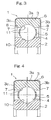
- the annular tool reference plane 7 may be defined in each of the opposite annular end faces 3b and 3c of the outer race 3 as shown in Fig. 3.
- the annular tool reference plane 7 in each of the opposite annular end faces 3b and 3c of the outer race 3 is defined by an indented radial surface, i.e., a bottom surface of the step 8 formed in the outer race 3.
- the annular tool reference plane 7 may be defined in the form of an annular bare surface area in each of the annular end faces 3b and 3c of the outer race 3, which are left uncovered by the insulating layer 6.
- respective surface areas of the annular end faces 3b and 3c of the outer race 3 are not thermally sprayed so that those surface areas left uncovered by the insulating layer 6 can be utilized as the tool reference planes 7.
- the annular tool reference plane has to be formed in a manner described in connection with any one of the foregoing embodiments. It is also to be noted that while in any one of the foregoing embodiments reference has been made to the deep groove ball bearing assembly, the present invention can be equally applied to a cylindrical roller bearing assembly or any other rolling bearing assembly in which the insulating layer 6 is desired or required to be formed.
- the electrocorrosion preventive rolling bearing assembly includes, as best shown in Fig. 5, an inner race 21 defining an inner raceway member and an outer race 22 defining an outer raceway member, with at least one circumferential row of a plurality of rolling elements 23 rollingly interposed between the inner and outer races 21 and 22.
- This electrocorrosion preventive rolling bearing assembly also includes an insulating layer 24 formed so as to cover an outer peripheral surface and opposite annular end faces of the outer race 22 lying generally perpendicular to the outer peripheral surface 3a.
- the inner and outer races 21 and 22 have respective raceway grooves (only the raceway groove in the outer race 22 being indicated by 22c) defined in outer and inner peripheral surfaces thereof, respectively, and the circumferential rows of the rolling elements 23 are received in part within the raceway groove 22c in the outer race 22 and in part within the raceway groove in the inner race 21.
- a portion of the inner peripheral surface of the outer race 3 excluding a surface area thereof where the raceway groove 22c i.e., inner peripheral surface areas on respective sides of the raceway groove 22c
- a cylindrical tool reference plane 22a which is so shaped as to conform to the contour of the outer peripheral surface 26a of the tapered mandrel 26.
- that portion of the inner peripheral surface of the outer race 3 excluding the raceway groove 22c is similarly tapered and defines the tool reference plane 22a.
- the electrocorrosion preventive rolling bearing assembly may be utilized for rotatably supporting a rotor of a primary electric motor of, for example, a railway vehicle.
- This electrocorrosion preventive rolling bearing assembly is a deep groove ball bearing and the rolling elements 23 are each represented by a ball and are rollingly retained by a retainer or cage 25.
- the inner and outer races 21 and 22, the rolling elements 23 and the retainer 25 are all made of a metallic material such as a bearing steel or the like.
- the electrically insulating layer 24 is made of, for example, a ceramic material and is formed by thermally spraying the ceramic material so as to cover the outer peripheral surface and annular end faces of the outer race 22.
- the ceramic material may be a metallic oxide such as alumina (Al 2 O 3 ), titanium oxide (TiO 2 or chromium oxide (Cr 2 O 3 ), or a compound metallic oxide containing at least one of those metallic oxides as a base material.
- a resinous material may also be employed. Where the resinous material is employed, a polyphenylene sulfide (PPS resin) resin is preferred.
- the electrically insulating layer 24 may be of either a single layer structure or a multi-layered structure.
- the cylindrical tool reference plane 22a so defined in the outer race 22 is tapered at a gradient of 1/100 to 1/3000. This gradient of the cylindrical tool reference plane 22a is so selected as to match the gradient of the tapered outer peripheral surface 26a of the tapered mandrel 26 that is inserted into the inner peripheral surface of the outer race 22 in a manner as shown in Fig. 6, at the time of performing a final machining of the outer peripheral surface of the outer race 22.
- the tapered mandrel 26 is inserted into the opening of the outer race 22 in a manner as shown in Fig. 6 and, then, the outer diameter of the outer race 22 is tailored to a predetermined or required value by means of, for example, a grinding technique while the tapered mandrel 26 is fixed to the outer race 22 and is rotated together therewith.
- FIG. 7 A fifth preferred embodiment of the present invention is shown in Fig. 7.
- the electrocorrosion preventive rolling bearing assembly shown therein is a cylindrical roller bearing assembly of which outer race 22 has a rib 22b defined in each of opposite ends thereof.
- the rolling elements 23 employed therein may be rollingly retained within respective pockets in the retainer, or the retainer or cage may be dispensed with to provide a full complement ball or roller bearing.
- Other structural features of the bearing assembly shown in Fig. 7 are similar to those in connection with the fourth embodiment shown and described with reference to Figs. 5 and 6 and, therefore, the details thereof are not reiterated for the sake of brevity.
- the tapered mandrel 26 when the tapered mandrel 26 is inserted into the opening of the outer race 22 in a manner as shown in Fig. 8 and, then, the outer diameter of the outer race 22 is tailored to a predetermined or required value while the tapered mandrel 26 is rotated together with the outer race 22, the tapered mandrel 26 can be stably fixed to the inner peripheral surface of the outer race 22. Because of this, the process of finishing the outer diameter of the outer race 22 can be performed easily and accurately.
- the tool reference plane 22a in the outer race 22 has been shown and described as tapered, the tool reference plane 22a may have an axial sectional shape representing a curved surface, e.g., a substantially arcuate surface, or a stepped surface, or may be represented by an inner peripheral surface of an annular projection (not shown) formed in the inner peripheral surface of the outer race 22.
Landscapes
- Engineering & Computer Science (AREA)
- General Engineering & Computer Science (AREA)
- Mechanical Engineering (AREA)
- Chemical & Material Sciences (AREA)
- Organic Chemistry (AREA)
- Chemical Kinetics & Catalysis (AREA)
- Materials Engineering (AREA)
- Metallurgy (AREA)
- Plasma & Fusion (AREA)
- Physics & Mathematics (AREA)
- Manufacturing & Machinery (AREA)
- Power Engineering (AREA)
- Rolling Contact Bearings (AREA)
Abstract
Description
- The present invention generally relates to a rolling bearing assembly adapted to prevent electrocorrosion due to an electric current flowing in rolling bearings utilized in a general purpose motor, an electric power generator or a traction motor of railway.
- Electrocorrosion preventive rolling bearing assemblies have been well known in the art and are disclosed in, for example, the Japanese Laid-open Patent Publication No. 2002-48145 and the Japanese Laid-open Utility Model Publication No. 2-46119. According to these publications, an electrocorrosion preventive rolling bearing assembly has an insulating layer formed by the use of a thermal spraying technique. The electrocorrosion preventive rolling bearing assembly having the insulating layer includes raceway members of which outer peripheral surfaces and annular end faces are covered by a metallic layer and an insulating layer.
- In the case of the structure in which the insulating layer is formed, it appears that the difference in thickness of the insulating layer at the annular end faces may increase at the time of finishing work unless the thickness of the insulating layer is controlled and, hence, the insulating property may decrease consequently. When it comes to the thickness control of an insulating layer, thickness control of an insulating layer at the annular end faces of the deep groove ball bearing assembly has to be generally on the basis of raceway grooves and, on the other hand, such thickness control of the insulating layer at the annular end faces of the cylindrical roller bearing assembly has to be generally performed on the basis of rib surfaces of raceway members. Accordingly, not only are complicated work procedures required with a considerable length of time for complete measurements, but also since the end face machining work results in poor precision when performed directly on the basis of the raceway grooves or the ribs, a substantial amount of time and labor is required in accomplishing the work, thereby posing a problem associated with increase of the manufacturing cost.
- Also, for mounting the outer race onto a housing by means of a crimping technique, a finishing work of the outer periphery of the outer race is generally carried out on the basis of the inner peripheral surface of the outer race as discussed below where the outer peripheral surface of the outer race that is covered by an electrically insulating layer requires the finishing work. Specifically, with reference to Fig. 9, this finishing work is carried out by fixing a
tapered mandrel 36 along the inner peripheral surface of theouter race 32 and, then, while theouter race 32 is rotated together with thetapered mandrel 36, the outer peripheral surface of theouter race 32 is machined, for example, ground to the required dimension. - However, since the inner peripheral surface of the outer race of the bearing assembly is generally of a cylindrical shape, the machining technique shown in and described with reference to Fig. 9 has a problem in that even though the inner periphery of the
outer race 32 is fixed at one end thereof to thetapered mandrel 36, a gap is naturally formed at the opposite end of theouter race 32 between the latter and thetapered mandrel 36. Because of this, there is a high possibility that during the machining theouter race 32 may be displaced and/or inclined relative to thetapered mandrel 36. Also, considering that theouter race 32 undergoes a thermal expansion by the effect of heat evolved during the machining, displacement and/or inclination of theouter race 32 relative to thetapered mandrel 36 are apt to occur more often than at normal temperatures. Once the displacement and/or inclination of theouter race 32 occur during the machining, it leads to poor precision (roundness, slant of the outer peripheral surface, radial deflection and so on) of the outer peripheral surface of theouter race 32. In order to alleviate these problems, the machining is typically performed while theouter race 32 is restrained, requiring further complicated work procedures. - In view of the foregoing, the present invention is intended to provide an electrocorrosion preventive rolling bearing assembly wherein the final machining of the electrically insulating layer discussed above and the thickness control of the insulating layer can easily and accurately be accomplished.
- In order to accomplish the foregoing object, as solved by the independent claim, the present invention provides an electrocorrosion preventive rolling bearing assembly which includes an inner race or an inner raceway member, an outer race or an outer raceway member, and at least one circumferential row of a plurality of rolling elements rollingly interposed between the inner and outer races. An electrically insulating layer is formed on at least one of the inner and outer raceway members so as to cover a peripheral surface and opposite annular end faces of such at least one of the inner and outer raceway members. The peripheral surface of such at least one of the inner and outer raceway members is for engagement with either a housing or a shaft. A tool reference plane utilizable for a process of finishing the electrically insulating layer or for a thickness control of the insulating layer is defined in at least one of opposite sides of raceway grooves of such at least one of the inner and outer races.
- Because of the tool reference plane being defined on one or both of the opposite sides of the raceway groove of the raceway member, the tool reference plane can be utilized directly when the electric insulating layer is finished to a predetermined size by means of a machining technique or when the thickness control of the insulating layer is performed after the machining. Accordingly, any otherwise complicated work such as required when a raceway groove or a rib surface of an inner or outer race is utilized as a tool reference plane can be advantageously eliminated, allowing the thickness control of the insulating layer after the machining to be performed easily and accurately.
- More specifically, the tool reference plane may be defined by an indented radial surface area of a step defined in the end face of the raceway member. Where the tool reference plane is defined by the step, the tool reference plane can be secured with high precision by means of a highly precise machining of forming the step.
- The tool reference plane may be alternatively defined by a bare surface area in the end face of the raceway member, which area is left uncovered by the insulating layer. Since the tool reference plane can be defined merely by leaving a portion of the end face uncovered with the electrically insulating layer, the tool reference plane can be formed easily.
- The tool reference plane may be formed by means of a hardened steel cutting process or a grinding process. With these processes, a highly precise machining can be achieved, resulting in the tool reference with a high precision.
- Also, the tool reference plane may be provided on respective sides of a raceway groove formed on the inner peripheral surface of an outer raceway member so as to engage an outer peripheral surface of a tapered mandrel along the entire axial length of the plane.
- Considering that the tapered mandrel is inserted into an inner peripheral surface when the outer diameter of the outer race is subjected to a final machining, the tool reference plane defined on those sides of the raceway groove is effective to allow the outer race to be held in stable contact with the mandrel since the tool reference plane is firmly engageable with the mandrel along the entire axial length of the plane. For this reason, an undesirable inclination and/or distortion of the outer race relative to the tapered mandrel during the outer diameter finishing process will hardly occur, keeping the outer race held firmly in position during such process. As such, no complicated procedure such as required hitherto in the art is required and the process of finishing the outer diameter of the outer race can be performed easily and accurately.
- The tool reference plane may represent a tapered surface or a curved surface such as a substantially arcuate surface in an axial sectional view, or may be represented by an inner peripheral surface of an annular projection formed on the inner peripheral surface of the outer race.
- Where the tool reference plane is in the form of a tapered surface, the use of the tapered mandrel having the same gradient as that of the tapered surface of the outer race is effective to allow the tapered surface of the mandrel to be held in surface contact with the tapered surface of the inner periphery of the outer race at the time of the final machining of the outer periphery of the outer race. The surface contact so achieved is effective to make it more difficult for the inclination and/or distortion of the outer race to occur during the outer diameter machining, allowing the posture to be stabilized.
- Where the inner peripheral surface of the outer race is represented by the tapered surface as described above, the tapered surface preferably has a gradient of 1/100 to 1/3000. Although the gradient of the tapered surface is preferred to be large so that the outer race can be firmly positioned on the tapered mandrel, the presence of a too large gradient in the inner peripheral surface of the outer race is undesirable in view of designing dimensions of various parts of the bearing assembly. The gradient of the tapered surface within the range of 1/100 to 1/3000 has been found desirable because the outer race can be firmly fixed to the tapered mandrel and because it does not pose any problem in designing the dimensions of various parts of the bearing assembly.
- Where the tool reference plane engageable with the outer peripheral surface of the tapered mandrel is provided, the electrically insulating layer may be a layer made of a ceramic material or a layer of a synthetic resin, for example, a polyphenylene sulfide resin. In the case of the ceramic material used for the electrically insulating layer, the electrically insulating layer having an excellent electric insulation and an excellent dimensional stability to change in temperature can be obtained advantageously. On the other hand, in the case of the polyphenylene sulfide resin employed for the electrically insulating layer, since of various resins the polyphenylene sulfide resin is excellent in ease to molding, the electrically insulating layer excellent in dimensional stability and electric insulation can be easily formed.
- Also, the electrocorrosion preventive rolling bearing assembly may be either a deep groove ball bearing or a cylindrical roller bearing of which outer race has a rib. Those types of the bearing assemblies pose no problem even if a portion of the inner peripheral surface of the outer race except for the raceway groove is formed as a tapered surface, or the end surface of the outer race is rendered to have a large surface area, and will, accordingly, provide a rolling bearing assembly having an excellent insulating property with the outer peripheral surface and the annular end faces of the outer race sufficiently covered by the electrically insulating layer.
- In any event, the present invention will become more clearly understood from the following description of preferred embodiments thereof, when taken in conjunction with the accompanying drawings, which illustrate preferred embodiments of the invention. In the accompanying drawings, like reference numerals are used to denote like parts throughout the several views, and:
- Fig. 1 is a fragmentary longitudinal sectional view of an electrocorrosion preventive rolling bearing assembly according to a first preferred embodiment of the present invention;
- Fig. 2 is an explanatory diagram showing an example of a method of machining opposite annular end faces of an outer race of the rolling bearing assembly;
- Fig. 3 is a fragmentary longitudinal sectional view of an electrocorrosion preventive rolling bearing assembly according to a second preferred embodiment of the present invention;
- Fig. 4 is a fragmentary longitudinal sectional view of an electrocorrosion preventive rolling bearing assembly according to a third preferred embodiment of the present invention;
- Fig. 5 is a fragmentary longitudinal sectional view of an electrocorrosion preventive rolling bearing assembly according to a fourth preferred embodiment of the present invention;
- Fig. 6 is a longitudinal sectional view of the rolling bearing assembly of Fig. 5, showing an example of a method of machining an outer periphery of the outer race of the rolling bearing assembly;
- Fig. 7 is a fragmentary longitudinal sectional view of an electrocorrosion preventive rolling bearing assembly according to a fifth preferred embodiment of the present invention;
- Fig. 8 is a longitudinal sectional view of the rolling bearing assembly of Fig. 7, showing an example of a method of machining an outer periphery of the outer race of the rolling bearing assembly; and
- Fig. 9 is an explanatory diagram showing a conventional method of machining an outer periphery of an outer race of a rolling bearing.
-
- A first preferred embodiment of the present invention will now be described with particular reference to Figs. 1 and 2. An electrocorrosion preventive rolling
bearing assembly 1 shown therein includes aninner race 2 defining an inner raceway member and anouter race 3 defining an outer raceway member, with at least one circumferential row of a plurality ofrolling elements 4 rollingly interposed between the inner andouter races bearing assembly 1 also includes aninsulating layer 6 formed so as to cover an outerperipheral surface 3a of theouter race 3, which is engaged with a housing (not shown), and oppositeannular end faces peripheral surface 3a. One of the opposite annular end faces of theouter race 3, for example, theend face 3b is provided with an annulartool reference plane 7 defined therein. The electrocorrosion preventive rollingbearing assembly 1 is a deep groove ball bearing and, hence, therolling elements 4 are each represented by a ball. The inner andouter races respective raceway grooves rolling elements 4 are received in part within theraceway groove 10 and in part within theraceway groove 11. Therolling elements 4 are retained within respective pockets defined in a retainer orcage 5 at respective locations circumferentially thereof. - The insulating layer formed on the
outer race 3 may be of either a single layer structure or a multilayer structure. The annulartool reference plane 7 is a surface used for the end face machining or for the thickness control of the insulating layer on the end face and is formed in an inner peripheral edge of theend face 3b of theouter race 3 adjacent theraceway groove 11. In other words, Thistool reference plane 7 is defined by an indented radial surface of anannular step 8 formed in an inner peripheral edge of theend face 3b of theouter race 3. Theannular step 8 has an outer diameter and a depth that generally correspond to the size left by removal of that portion of an inner peripheral surface of theouter race 3 where an chamferedsurface 3d is formed. Theannular step 8 may be formed by machining either prior to or after a thermal spraying employed to form the insulatinglayer 6 on theouter race 3. This machining may be, for example, a grinding process or a hardened steel cutting process. The inner andouter races elements 4 are all made of steel such as a bearing steel. - The insulating
layer 6 formed on a material surface of theouter race 3 by the use of a thermal spraying technique is prepared from a metallic oxide such as aluminum oxide (Al2O3), titanium oxide (TiO2) or chromium oxide (Cr2O3), or compound metallic oxide containing one or more of such metallic oxides. This insulatinglayer 6 is, after the thermal spraying, subjected to a machining process as will subsequently be described. The difference in thickness of the insulatinglayer 6 between the left and right annular end faces 3b and 3c is preferably to be suppressed to a value not greater than 50 µm. Also, the parallelism thetool reference plane 7 and theend face 3b prior to the thermal spraying is preferably not greater than 25 µm. - According to the foregoing embodiment shown in and described with reference to Figs. 1 and 2, the use of the
tool reference plane 7 defined in theend face 3b of theouter race 3 is advantageous in that thetool reference plane 7 can be utilized directly when the annular end faces 3b and 3c are being finished by means of the machining to a predetermined dimension or during the thickness control of the insulating layer on the annular end faces 3b and 3c after the machining. Accordingly, any otherwise complicated work such as required when therace groove 11 of theouter race 3 would be utilized as a tool reference plane can be advantageously eliminated, allowing the thickness control of the insulatinglayer 6 after the machining to be performed easily and accurately. Since thetool reference plane 7 can be defined in the form of thestep 8, theplane 7 can be formed with high precision by a machining work. Also, if thetool reference plane 7 is formed by means of a grinding process or a hardened steel cutting process, it is possible to form it more precisely. - An example of the end face machining employed in the illustrated embodiment will now be described with reference to Fig. 2. This end face machining is carried through the following sequential steps (1) to (4):
- (1) With respect to all products, the first width (the axial length) A
between the annular
tool reference plane 7 in theouter race 3 and theend face 3c of theouter race 3 remote from thetool reference plane 7 is measured prior to the thermal spraying. - (2) After the thermal spraying having been effected, the second width B
between the annular
tool reference plane 7 and the annular outer surface of the insulatinglayer 6 on the end face 3c is measured to determine a depth of cut or an axial dimension to cut in by machining for the end face of the insulatinglayer 6 on theend face 3c remote from thetool reference plane 7. With thetool reference plane 7 applied to a backing plate 15, the end face of the insulatinglayer 6 remote from thetool reference plane 7 is machined by means of, for example, a grinding technique. - (3) With reference to a target dimension desired to be achieved and the
total width C as measured between the opposite annular end faces 3b and 3c
which are covered by the insulating
layer 6, another depth of cut is determined. - (4) With the
machined end face 3c taken as a reference, theopposite end face 3b adjacent thetool reference plane 7 is machined so as to allow it to fall within the allowance of the final width. -
- According to the theoretical calculation, variation in insulating performance in each product can be minimized when the difference in thickness of the respective end surfaces of the insulating
layer 6 covering the annular end faces 3b and 3c is suppressed to 50 µm by means of the method discussed above. For example, with the method discussed above, the difference in dielectric withstanding voltage between the respective end surfaces of the insulatinglayer 6 can be suppressed to a value equal to or lower than 0.5 kV Also, the depth of cut can easily be controlled and reduction in number of machining steps can be appreciated. - According to the foregoing embodiment, the annular
tool reference plane 7 has been shown and described as defined in only one of the opposite annular end faces of theouter race 3. However, according to a second embodiment, the annulartool reference plane 7 may be defined in each of the opposite annular end faces 3b and 3c of theouter race 3 as shown in Fig. 3. Even in this second embodiment shown in Fig. 3, the annulartool reference plane 7 in each of the opposite annular end faces 3b and 3c of theouter race 3 is defined by an indented radial surface, i.e., a bottom surface of thestep 8 formed in theouter race 3. - Also, in a third preferred embodiment of the present invention shown in Fig. 4, the annular
tool reference plane 7 may be defined in the form of an annular bare surface area in each of the annular end faces 3b and 3c of theouter race 3, which are left uncovered by the insulatinglayer 6. In other words, respective surface areas of the annular end faces 3b and 3c of theouter race 3 are not thermally sprayed so that those surface areas left uncovered by the insulatinglayer 6 can be utilized as the tool reference planes 7. - It is to be noted that where a similar
insulating layer 6 is to be formed on theinner race 2 in a manner similar to that on theouter race 3, the annular tool reference plane has to be formed in a manner described in connection with any one of the foregoing embodiments. It is also to be noted that while in any one of the foregoing embodiments reference has been made to the deep groove ball bearing assembly, the present invention can be equally applied to a cylindrical roller bearing assembly or any other rolling bearing assembly in which the insulatinglayer 6 is desired or required to be formed. - With reference to Figs. 5 and 6, a fourth preferred embodiment of the present invention will now be described. The electrocorrosion preventive rolling bearing assembly includes, as best shown in Fig. 5, an
inner race 21 defining an inner raceway member and anouter race 22 defining an outer raceway member, with at least one circumferential row of a plurality of rollingelements 23 rollingly interposed between the inner andouter races layer 24 formed so as to cover an outer peripheral surface and opposite annular end faces of theouter race 22 lying generally perpendicular to the outerperipheral surface 3a. The inner andouter races outer race 22 being indicated by 22c) defined in outer and inner peripheral surfaces thereof, respectively, and the circumferential rows of the rollingelements 23 are received in part within theraceway groove 22c in theouter race 22 and in part within the raceway groove in theinner race 21. - A portion of the inner peripheral surface of the
outer race 3 excluding a surface area thereof where theraceway groove 22c (i.e., inner peripheral surface areas on respective sides of theraceway groove 22c) is defined as a cylindricaltool reference plane 22a which is so shaped as to conform to the contour of the outerperipheral surface 26a of the taperedmandrel 26. Hence, that portion of the inner peripheral surface of theouter race 3 excluding theraceway groove 22c is similarly tapered and defines thetool reference plane 22a. - The electrocorrosion preventive rolling bearing assembly may be utilized for rotatably supporting a rotor of a primary electric motor of, for example, a railway vehicle. This electrocorrosion preventive rolling bearing assembly is a deep groove ball bearing and the rolling
elements 23 are each represented by a ball and are rollingly retained by a retainer or cage 25. The inner andouter races elements 23 and the retainer 25 are all made of a metallic material such as a bearing steel or the like. - The electrically insulating
layer 24 is made of, for example, a ceramic material and is formed by thermally spraying the ceramic material so as to cover the outer peripheral surface and annular end faces of theouter race 22. The ceramic material may be a metallic oxide such as alumina (Al2O3), titanium oxide (TiO2 or chromium oxide (Cr2O3), or a compound metallic oxide containing at least one of those metallic oxides as a base material. For the electric insulatinglayer 24, a resinous material may also be employed. Where the resinous material is employed, a polyphenylene sulfide (PPS resin) resin is preferred. Also, the electrically insulatinglayer 24 may be of either a single layer structure or a multi-layered structure. - The cylindrical
tool reference plane 22a so defined in theouter race 22 is tapered at a gradient of 1/100 to 1/3000. This gradient of the cylindricaltool reference plane 22a is so selected as to match the gradient of the tapered outerperipheral surface 26a of the taperedmandrel 26 that is inserted into the inner peripheral surface of theouter race 22 in a manner as shown in Fig. 6, at the time of performing a final machining of the outer peripheral surface of theouter race 22. - In the electrocorrosion preventive rolling bearing assembly of the structure according to the fourth embodiment discussed above, because of the electrically insulating
layer 24 interposed between theouter race 22 and a housing to which the rolling bearing assembly is mounted, an insulating property can be secured not only therebetween but also between a shaft, which may be engaged in theinner race 21, and the housing. For this reason, it is possible to prevent raceway surfaces from being roughened which would otherwise result from sparks taking place between the respective raceway grooves of the inner andouter races elements 23. - On manufacture of the rolling bearing assembly of the structure described above, the tapered
mandrel 26 is inserted into the opening of theouter race 22 in a manner as shown in Fig. 6 and, then, the outer diameter of theouter race 22 is tailored to a predetermined or required value by means of, for example, a grinding technique while the taperedmandrel 26 is fixed to theouter race 22 and is rotated together therewith. Since at this time, thetool reference plane 22a in the inner peripheral surface of theouter race 22 is held in a surface contact with the outerperipheral surface 26a of the taperedmandrel 26 and the taperedmandrel 26 is hence stably fixed to the inner peripheral surface of theouter race 22, an undesirable inclination and/or distortion of theouter race 22 relative to the taperedmandrel 26 during the outer diameter finishing process will hardly occur. As such, no complicated procedure such as required hitherto in the art is required and the process of finishing the outer diameter of theouter race 22 can be performed easily and accurately. - A fifth preferred embodiment of the present invention is shown in Fig. 7. Referring to Fig. 7, the electrocorrosion preventive rolling bearing assembly shown therein is a cylindrical roller bearing assembly of which
outer race 22 has arib 22b defined in each of opposite ends thereof. The rollingelements 23 employed therein may be rollingly retained within respective pockets in the retainer, or the retainer or cage may be dispensed with to provide a full complement ball or roller bearing. Other structural features of the bearing assembly shown in Fig. 7 are similar to those in connection with the fourth embodiment shown and described with reference to Figs. 5 and 6 and, therefore, the details thereof are not reiterated for the sake of brevity. - Even in the embodiment shown in and described with reference to Fig. 7, when the tapered
mandrel 26 is inserted into the opening of theouter race 22 in a manner as shown in Fig. 8 and, then, the outer diameter of theouter race 22 is tailored to a predetermined or required value while the taperedmandrel 26 is rotated together with theouter race 22, the taperedmandrel 26 can be stably fixed to the inner peripheral surface of theouter race 22. Because of this, the process of finishing the outer diameter of theouter race 22 can be performed easily and accurately. - It is to be noted that while in the foregoing embodiment the
tool reference plane 22a in theouter race 22 has been shown and described as tapered, thetool reference plane 22a may have an axial sectional shape representing a curved surface, e.g., a substantially arcuate surface, or a stepped surface, or may be represented by an inner peripheral surface of an annular projection (not shown) formed in the inner peripheral surface of theouter race 22. - Although the present invention has been fully described in connection with the preferred embodiments thereof with reference to the accompanying drawings which are used only for the purpose of illustration, those skilled in the art will readily conceive numerous changes and modifications within the framework of obviousness upon the reading of the specification herein presented of the present invention. Accordingly, such changes and modifications are, unless they depart from the scope of the present invention as delivered from the claims annexed hereto, to be construed as included therein.
Claims (11)
- An electrocorrosion preventive rolling bearing assembly (1) which comprises:an inner raceway member (2, 21);an outer raceway member (3, 22);at least one circumferential row of a plurality of rolling elements (4, 23) rollingly interposed between respective raceway grooves (10, 11, 22c) of the inner and outer raceway members;an electrically insulating layer (6, 24) formed on at least one of the inner and outer raceway members so as to cover a peripheral surface (3a) and opposite annular end faces (3b, 3c) of such at least one of the inner and outer raceway members, the peripheral surface of such at least one of the inner and outer raceway members being engageable with either a housing or a shaft; anda tool reference plane (7, 22a) defined in at least one of opposite sides of the raceway groove (10, 11, 22a) of the raceway member, the tool reference plane being utilizable for a process of finishing the electrically insulating layer or for a thickness control of the insulating layer (6, 24).
- The electrocorrosion preventive rolling bearing assembly as claimed in Claim 1, wherein the tool reference plane is utilizable for a process of finishing respective portions of the electrically insulating layer covering the opposite annular end faces or for a thickness control of those portions of the electrically insulating layer and wherein the tool reference plane is defined by an indented radial surface area of a step defined in the isde face of the raceway member.
- The electrocorrosion preventive rolling bearing assembly as claimed in Claim 1 or 2, wherein the tool reference plane is defined by a bare surface area in the end face of the raceway member, which is left uncovered by the insulating layer.
- The electrocorrosion preventive rolling bearing assembly as claimed in one of the Claims 1 to 3, wherein the tool reference plane is a surface area formed by means of a hardened steel cutting process or a grinding process.
- The electrocorrosion preventive rolling bearing assembly as claimed in one of the Claims 1 to 4, wherein the electrically insulating layer is provided on an outer peripheral surface and opposite annular end faces of the outer raceway member and wherein the tool reference plane is provided on respective sides of the raceway groove defined on the inner peripheral surface of the outer raceway member and is engageable with an outer peripheral surface of a tapered mandrel.
- The electrocorrosion preventive rolling bearing assembly as claimed in one of the Claims 1 to 5, wherein the electrically insulating layer is provided on an outer peripheral surface and opposite annular end faces of the outer raceway member and wherein the tool reference plane represents a tapered surface defined by portions of the inner peripheral surface of the outer race excluding the raceway groove defined adjacent such portions.
- The electrocorrosion preventive rolling bearing assembly as claimed in one of the Claims 1 to 6, wherein a tapered surface which is an inner peripheral surface of the outer race has a gradient of 1/100 to 1/3000.
- The electrocorrosion preventive rolling bearing assembly as claimed in one of the Claims 1 to 7, wherein the electrically insulating layer is a layer made of a ceramic material.
- The electrocorrosion preventive rolling bearing assembly as claimed in one of the Claims 1 to 8, wherein the electrically insulating layer is made of a polyphenylene sulfide resin.
- The electrocorrosion preventive rolling bearing assembly as claimed in one of the Claims 1 to 9, which is a deep groove ball bearing.
- The electrocorrosion preventive rolling bearing assembly as claimed in one of the Claims 1 to 10, which is a cylindrical roller bearing of which outer race has a rib.
Applications Claiming Priority (4)
| Application Number | Priority Date | Filing Date | Title |
|---|---|---|---|
| JP2002294436 | 2002-10-08 | ||
| JP2002294436A JP2004132385A (en) | 2002-10-08 | 2002-10-08 | Electric erosion preventing rolling bearing |
| JP2002309200A JP2004144184A (en) | 2002-10-24 | 2002-10-24 | Electrocorrosion preventive rolling bearing |
| JP2002309200 | 2002-10-24 |
Publications (2)
| Publication Number | Publication Date |
|---|---|
| EP1408249A1 true EP1408249A1 (en) | 2004-04-14 |
| EP1408249B1 EP1408249B1 (en) | 2008-04-09 |
Family
ID=32032947
Family Applications (1)
| Application Number | Title | Priority Date | Filing Date |
|---|---|---|---|
| EP03022450A Expired - Lifetime EP1408249B1 (en) | 2002-10-08 | 2003-10-07 | Rolling bearing protected against electrocorrosion |
Country Status (5)
| Country | Link |
|---|---|
| US (1) | US7097362B2 (en) |
| EP (1) | EP1408249B1 (en) |
| KR (1) | KR100984708B1 (en) |
| CN (1) | CN100427784C (en) |
| DE (1) | DE60320197T2 (en) |
Cited By (4)
| Publication number | Priority date | Publication date | Assignee | Title |
|---|---|---|---|---|
| DE102016202399A1 (en) | 2015-02-17 | 2016-08-18 | Aktiebolaget Skf | Electrically insulated bearing |
| WO2018050159A1 (en) * | 2016-09-13 | 2018-03-22 | Schaeffler Technologies AG & Co. KG | Bearing ring with an electrically insulating coating and method for producing an electrically insulating coating |
| WO2019216841A1 (en) * | 2018-05-09 | 2019-11-14 | Ortadogu Rulman Sanayi Ve Ticaret Anonim Sirketi | Electrical insulated roller bearing production method |
| DE102020201509A1 (en) | 2020-02-07 | 2021-08-12 | Minebea Mitsumi Inc. | Rolling bearing with an electrically insulating layer and method for applying an electrically insulating layer |
Families Citing this family (15)
| Publication number | Priority date | Publication date | Assignee | Title |
|---|---|---|---|---|
| US20090116776A1 (en) * | 2005-09-15 | 2009-05-07 | Hideji Ito | Rolling Bearing and Spindle Support Structure of Main Motor for Railway Vehicle |
| KR20080100269A (en) * | 2006-03-08 | 2008-11-14 | 에누티에누 가부시키가이샤 | Rolling Bearing and Manufacturing Method |
| DE102009014753A1 (en) * | 2009-03-27 | 2010-09-30 | Schaeffler Technologies Gmbh & Co. Kg | Bearing ring with electrical insulation and process for its preparation |
| DE202012010830U1 (en) * | 2012-05-11 | 2012-11-27 | Schaeffler Technologies AG & Co. KG | Rolling bearing assembly, in particular for a radial rolling bearing |
| JP6590686B2 (en) * | 2014-12-24 | 2019-10-16 | トーカロ株式会社 | Insulated bearing and bearing coating method |
| US10605304B2 (en) | 2016-04-12 | 2020-03-31 | Nsk Ltd. | Insulated bearing |
| DE102017218844A1 (en) * | 2016-11-07 | 2018-05-09 | Aktiebolaget Skf | Coating process for a bearing ring |
| JP7134639B2 (en) | 2017-03-24 | 2022-09-12 | アクティエボラゲット・エスコーエッフ | Rolling bearing with electrical insulating layer |
| US10422384B2 (en) * | 2018-01-25 | 2019-09-24 | Aktiebolaget Skf | Electrical insulating device for bearings |
| US10931179B2 (en) | 2018-03-20 | 2021-02-23 | Aktiebolaget Skf | Fiber grounding brush |
| DE102018206242A1 (en) | 2018-04-24 | 2019-10-24 | Aktiebolaget Skf | Rolling bearing having electrical insulation material, and manufacturing method of such a rolling bearing |
| FR3104655B1 (en) * | 2019-12-16 | 2021-12-24 | Safran Helicopter Engines | Three point contact bearing with improved drain |
| KR20230064539A (en) * | 2021-11-01 | 2023-05-10 | 셰플러코리아 유한책임회사 | An Electric Isolated Rolling Bearing |
| CN118513220A (en) * | 2023-02-17 | 2024-08-20 | 斯凯孚公司 | Rolling bearings and electrical insulation coatings thereof |
| CN116877586B (en) * | 2023-08-03 | 2023-12-15 | 苏州铁近机电科技股份有限公司 | Anti-electric corrosion bearing |
Citations (4)
| Publication number | Priority date | Publication date | Assignee | Title |
|---|---|---|---|---|
| JPS59103023A (en) * | 1982-12-02 | 1984-06-14 | Nippon Seiko Kk | Electric corrosion inhibitive type rolling bearing |
| DE19525702A1 (en) * | 1995-07-14 | 1997-01-16 | Fag Aircraft Gmbh | Wear protected roller bearing - has wear and/or corrosion resistant coating applied before heat treatment |
| US20010014545A1 (en) * | 1999-12-24 | 2001-08-16 | Kenji Ito | Electrical pittingproof rolling bearing |
| DE10161820A1 (en) * | 2000-12-14 | 2002-09-05 | Ntn Toyo Bearing Co Ltd | Electric corrosion prevention type bearing has reference plane provided to internal surface of outer wheel and subjected to grinding before providing ceramic thermal spraying insulating layer |
Family Cites Families (8)
| Publication number | Priority date | Publication date | Assignee | Title |
|---|---|---|---|---|
| US2370173A (en) * | 1941-08-25 | 1945-02-27 | Elizabeth B Dickson | Antifriction bearing |
| JPH0789690B2 (en) | 1988-08-05 | 1995-09-27 | 財団法人電力中央研究所 | How to install a cryogenic cable |
| JPH03103615A (en) * | 1989-09-12 | 1991-04-30 | Railway Technical Res Inst | Electrically insulated bearing |
| JP2779251B2 (en) * | 1990-03-26 | 1998-07-23 | エヌティエヌ株式会社 | Anti-corrosion rolling bearing |
| CN1133331A (en) * | 1995-04-12 | 1996-10-16 | 马金生 | Polyphenyl sulfoether resin anti-corrosive paint |
| US5961222A (en) * | 1996-03-29 | 1999-10-05 | Nsk Ltd. | Anti-electrolytic corrosion rolling bearing |
| CN2392027Y (en) * | 1999-11-05 | 2000-08-16 | 唐永健 | High-temperature deep groove ball bearing |
| JP4002069B2 (en) * | 2001-01-10 | 2007-10-31 | Ntn株式会社 | Manufacturing method of outer ring in electric corrosion prevention type bearing |
-
2003
- 2003-06-13 CN CNB031454151A patent/CN100427784C/en not_active Expired - Lifetime
- 2003-10-01 KR KR1020030068313A patent/KR100984708B1/en not_active Expired - Lifetime
- 2003-10-02 US US10/676,075 patent/US7097362B2/en not_active Expired - Lifetime
- 2003-10-07 DE DE60320197T patent/DE60320197T2/en not_active Expired - Lifetime
- 2003-10-07 EP EP03022450A patent/EP1408249B1/en not_active Expired - Lifetime
Patent Citations (4)
| Publication number | Priority date | Publication date | Assignee | Title |
|---|---|---|---|---|
| JPS59103023A (en) * | 1982-12-02 | 1984-06-14 | Nippon Seiko Kk | Electric corrosion inhibitive type rolling bearing |
| DE19525702A1 (en) * | 1995-07-14 | 1997-01-16 | Fag Aircraft Gmbh | Wear protected roller bearing - has wear and/or corrosion resistant coating applied before heat treatment |
| US20010014545A1 (en) * | 1999-12-24 | 2001-08-16 | Kenji Ito | Electrical pittingproof rolling bearing |
| DE10161820A1 (en) * | 2000-12-14 | 2002-09-05 | Ntn Toyo Bearing Co Ltd | Electric corrosion prevention type bearing has reference plane provided to internal surface of outer wheel and subjected to grinding before providing ceramic thermal spraying insulating layer |
Non-Patent Citations (1)
| Title |
|---|
| PATENT ABSTRACTS OF JAPAN vol. 008, no. 220 (M - 330) 6 October 1984 (1984-10-06) * |
Cited By (4)
| Publication number | Priority date | Publication date | Assignee | Title |
|---|---|---|---|---|
| DE102016202399A1 (en) | 2015-02-17 | 2016-08-18 | Aktiebolaget Skf | Electrically insulated bearing |
| WO2018050159A1 (en) * | 2016-09-13 | 2018-03-22 | Schaeffler Technologies AG & Co. KG | Bearing ring with an electrically insulating coating and method for producing an electrically insulating coating |
| WO2019216841A1 (en) * | 2018-05-09 | 2019-11-14 | Ortadogu Rulman Sanayi Ve Ticaret Anonim Sirketi | Electrical insulated roller bearing production method |
| DE102020201509A1 (en) | 2020-02-07 | 2021-08-12 | Minebea Mitsumi Inc. | Rolling bearing with an electrically insulating layer and method for applying an electrically insulating layer |
Also Published As
| Publication number | Publication date |
|---|---|
| DE60320197T2 (en) | 2009-07-09 |
| CN1490533A (en) | 2004-04-21 |
| EP1408249B1 (en) | 2008-04-09 |
| US7097362B2 (en) | 2006-08-29 |
| KR20040032054A (en) | 2004-04-14 |
| DE60320197D1 (en) | 2008-05-21 |
| CN100427784C (en) | 2008-10-22 |
| KR100984708B1 (en) | 2010-10-01 |
| US20040066997A1 (en) | 2004-04-08 |
Similar Documents
| Publication | Publication Date | Title |
|---|---|---|
| US7097362B2 (en) | Electrocorrosion preventive rolling bearing | |
| US9771980B2 (en) | Rolling bearing retainer and method for manufacturing such retainer | |
| US12196266B2 (en) | Bearing device with integrated electrical insulation, in particular for an electric motor or machine, and method of forming same | |
| US12196263B2 (en) | Bearing device with integrated electrical insulation, in particular for an electric motor or machine | |
| US12173754B2 (en) | Bearing device with integrated electrical insulation, in particular for an electric motor or machine | |
| US9618042B2 (en) | Inner ring with undercut to improve tang flexibility | |
| US9618044B2 (en) | Outer ring and roller bearing comprising said type of outer ring | |
| CN116412206A (en) | Bearing units with integrated electrical insulation, especially for electric motors or machines | |
| US4363527A (en) | Split race bearing | |
| JPH04210124A (en) | electrically insulated bearings | |
| CN117480327A (en) | Bearing units and electric motors | |
| EP0426279A2 (en) | Hollow roller bearing and method of making and mounting same | |
| JP4969552B2 (en) | Manufacturing method of electric corrosion prevention rolling bearing | |
| JP4980328B2 (en) | Anti-corrosion rolling bearing | |
| JP2004144184A (en) | Electrocorrosion preventive rolling bearing | |
| CN117616210A (en) | Insulated rolling bearings | |
| JP2010001934A (en) | Method of manufacturing raceway ring for electrolytic corrosion preventive insulated rolling bearing | |
| JP2004132385A (en) | Electric erosion preventing rolling bearing | |
| JP2006077944A (en) | Insulated rolling bearing for electric corrosion prevention | |
| US20250341234A1 (en) | Bearing device with integrated electric insulation, in particular for an electric machine or motor | |
| US20260002566A1 (en) | Bearing device with integrated electric insulation, in particular for an electric machine or motor | |
| CN117722441A (en) | Insulated bearing | |
| US20250271035A1 (en) | Bearing device with integrated electrical insulation, in particular for electric motor or electric machine | |
| JP7472633B2 (en) | Workpiece support device | |
| WO2020116218A1 (en) | Double row tapered roller bearing |
Legal Events
| Date | Code | Title | Description |
|---|---|---|---|
| PUAI | Public reference made under article 153(3) epc to a published international application that has entered the european phase |
Free format text: ORIGINAL CODE: 0009012 |
|
| AK | Designated contracting states |
Kind code of ref document: A1 Designated state(s): AT BE BG CH CY CZ DE DK EE ES FI FR GB GR HU IE IT LI LU MC NL PT RO SE SI SK TR |
|
| AX | Request for extension of the european patent |
Extension state: AL LT LV MK |
|
| 17P | Request for examination filed |
Effective date: 20040901 |
|
| AKX | Designation fees paid |
Designated state(s): DE DK FR |
|
| GRAP | Despatch of communication of intention to grant a patent |
Free format text: ORIGINAL CODE: EPIDOSNIGR1 |
|
| GRAS | Grant fee paid |
Free format text: ORIGINAL CODE: EPIDOSNIGR3 |
|
| GRAA | (expected) grant |
Free format text: ORIGINAL CODE: 0009210 |
|
| AK | Designated contracting states |
Kind code of ref document: B1 Designated state(s): DE DK FR |
|
| REF | Corresponds to: |
Ref document number: 60320197 Country of ref document: DE Date of ref document: 20080521 Kind code of ref document: P |
|
| ET | Fr: translation filed | ||
| PG25 | Lapsed in a contracting state [announced via postgrant information from national office to epo] |
Ref country code: DK Free format text: LAPSE BECAUSE OF FAILURE TO SUBMIT A TRANSLATION OF THE DESCRIPTION OR TO PAY THE FEE WITHIN THE PRESCRIBED TIME-LIMIT Effective date: 20080409 |
|
| PLBE | No opposition filed within time limit |
Free format text: ORIGINAL CODE: 0009261 |
|
| STAA | Information on the status of an ep patent application or granted ep patent |
Free format text: STATUS: NO OPPOSITION FILED WITHIN TIME LIMIT |
|
| 26N | No opposition filed |
Effective date: 20090112 |
|
| REG | Reference to a national code |
Ref country code: FR Ref legal event code: PLFP Year of fee payment: 14 |
|
| REG | Reference to a national code |
Ref country code: FR Ref legal event code: PLFP Year of fee payment: 15 |
|
| REG | Reference to a national code |
Ref country code: FR Ref legal event code: PLFP Year of fee payment: 16 |
|
| PGFP | Annual fee paid to national office [announced via postgrant information from national office to epo] |
Ref country code: FR Payment date: 20220908 Year of fee payment: 20 |
|
| PGFP | Annual fee paid to national office [announced via postgrant information from national office to epo] |
Ref country code: DE Payment date: 20220831 Year of fee payment: 20 |
|
| REG | Reference to a national code |
Ref country code: DE Ref legal event code: R071 Ref document number: 60320197 Country of ref document: DE |