EP1407991A1 - Vorrichtung zum Verschieben von auf einem Fördermittel geförderten Gegenständen - Google Patents
Vorrichtung zum Verschieben von auf einem Fördermittel geförderten Gegenständen Download PDFInfo
- Publication number
- EP1407991A1 EP1407991A1 EP03019108A EP03019108A EP1407991A1 EP 1407991 A1 EP1407991 A1 EP 1407991A1 EP 03019108 A EP03019108 A EP 03019108A EP 03019108 A EP03019108 A EP 03019108A EP 1407991 A1 EP1407991 A1 EP 1407991A1
- Authority
- EP
- European Patent Office
- Prior art keywords
- lever
- slide
- rotation
- axis
- conveying
- Prior art date
- Legal status (The legal status is an assumption and is not a legal conclusion. Google has not performed a legal analysis and makes no representation as to the accuracy of the status listed.)
- Granted
Links
- 230000033001 locomotion Effects 0.000 claims description 37
- 238000000034 method Methods 0.000 claims description 11
- 230000005540 biological transmission Effects 0.000 claims description 6
- 230000000284 resting effect Effects 0.000 claims 1
- 238000006073 displacement reaction Methods 0.000 description 9
- 238000010276 construction Methods 0.000 description 3
- 230000001133 acceleration Effects 0.000 description 1
- 230000009286 beneficial effect Effects 0.000 description 1
- 230000015572 biosynthetic process Effects 0.000 description 1
- 210000001520 comb Anatomy 0.000 description 1
- 230000008878 coupling Effects 0.000 description 1
- 238000010168 coupling process Methods 0.000 description 1
- 238000005859 coupling reaction Methods 0.000 description 1
- 230000001419 dependent effect Effects 0.000 description 1
- 230000005611 electricity Effects 0.000 description 1
- 239000002184 metal Substances 0.000 description 1
- 230000001960 triggered effect Effects 0.000 description 1
- 238000011144 upstream manufacturing Methods 0.000 description 1
Images

Classifications
-
- B—PERFORMING OPERATIONS; TRANSPORTING
- B65—CONVEYING; PACKING; STORING; HANDLING THIN OR FILAMENTARY MATERIAL
- B65G—TRANSPORT OR STORAGE DEVICES, e.g. CONVEYORS FOR LOADING OR TIPPING, SHOP CONVEYOR SYSTEMS OR PNEUMATIC TUBE CONVEYORS
- B65G47/00—Article or material-handling devices associated with conveyors; Methods employing such devices
- B65G47/74—Feeding, transfer, or discharging devices of particular kinds or types
- B65G47/82—Rotary or reciprocating members for direct action on articles or materials, e.g. pushers, rakes, shovels
Definitions
- the invention relates to a device for moving of objects funded on a grant according to the preamble of claim 1.
- Such devices are used when Items such as Boxes, boxes, magazine piles or the like, in general cargo formation on a Funding is funded and across the funding direction on which funding is to be moved.
- Items such as Boxes, boxes, magazine piles or the like
- Such devices are used when Items such as Boxes, boxes, magazine piles or the like, in general cargo formation on a Funding is funded and across the funding direction on which funding is to be moved.
- a moving process can be objects at right angles or at an angle to the conveying direction in one Funding process introduced or from a funding process be removed. It is also possible to find items from one grant to another grant implement objects on different grants to distribute, funded on multiple grants Merge objects on a grant or Sort items.
- a device of the type mentioned is from the JP-A-56065712 known.
- On a rotating driven A double arm lever is attached to the shaft, on the two Each end of another shaft is freely rotatable.
- Each of these additional shafts is via a wheel-belt transmission with a tubular, encompassing the shaft Part of a housing connected in which the drive for the shaft is arranged.
- a tab-shaped lever attached to the free end a third shaft is mounted on the one hand via another wheel-belt transmission with the Double arm lever is connected and on the other hand via a lever-shaped boom carries a slide.
- This well-known Device requires a considerable height and further it should hardly be suitable, very close to promote successive objects.
- Another device is, for example, from EP-A-0 532 978 known.
- There are two on the boom with each other connected slider reveals which on a run around an elongated circular path, with one half this elongated circular path in the conveyor area and the other half is outside the funding area.
- the both sliders are from an eccentric drive acts, which ensures that the slide at a relatively slow speed to the create objects to be moved, whereupon the Movement of the slide is accelerated.
- An object of the invention is a device to provide the type mentioned above, which with comparatively low economic effort compact and can be realized stably and at the same time allows tight on a funding successive objects at an angle to the conveying direction to postpone.
- the slide is thus rotatable on one two-piece articulated lever mounted from the above first and second levers.
- this simple Articulated lever arrangement can be provided with a achieve the appropriate drive with little effort, that the slide moves through the Conveying area moves while doing the desired shift of the object, whereby towards the end of the Moving the movement component across Direction of funding can be reduced all the more undesirable and especially uncontrolled Accelerations of the object at the end of the Avoid moving.
- the Sliders are easily controlled in such a way that it is also a component of motion in the direction of conveyance has so that it moves during the move to a certain extent with the object to be moved can follow what is a controlled move without or only with small relative movements between Allows slider and object.
- the Orbit of the slide by an appropriate Control of the first lever, second lever and slide be designed so that the slide during the Displacement movement and the subsequent Retraction movement seen in the direction of conveyance is comparatively takes up little space. In this respect, it is possible to moving objects according to the invention along the Allow funding to follow closely.
- the device has an extremely compact and stable construction on what a quick actuation at enables smooth running.
- the first lever, the second lever, the slider and the stationary support arm can be via a toothed belt and / or a gear transmission can be operatively connected.
- An example for such an active connection is within the Figure description explained.
- Double lever is formed, the two parts of which are in extend in opposite directions, with the Axis of rotation of the double lever in its central area located.
- the double lever is preferably vertical point symmetrical to its plane of rotation trained its axis of rotation.
- opposite ends can be the two parts of the double lever a second lever each of the above described type with a slide each have the type already described above.
- a such an arrangement can be in successive Sliding movements of both sliders alternately to Use, with both slides on one in Can move essentially triangular orbit that they are in the area of this orbit each are opposite.
- the first lever is preferably connected to a gearwheel, which is powered by a drive motor.
- the Drive motor can thereby be connected to one of the axis of rotation of the first lever remote location, what is in A compact design in the direction of the axis of rotation Allows device.
- the slider In order for the slide to rest as flat as possible on to reach moving object, the slider be rotatably mounted on the second lever such that who are in contact with the product to be moved bringing slide area throughout Orbital movement of the slide parallel to the conveying direction extends. So it takes place both during the Sliding movement as well as during the retracting movement the slide only a parallel displacement of the called slide surface.
- the slide area is about half the length of the second Lever spaced from its axis of rotation contributes to this an optimally shaped orbit.
- the lever can be rotated around its axis of rotation on one be held stationary arm, which itself especially up to a range above Funding extends.
- the support arm is so far arranged above that he was not on the grant funded objects collided.
- Levers and / or sliders can be driven intermittently so that a move is only ever triggered can be, if such is actually needed. Such a drive is useful, for example, if individual items from one along a conveyor transported electricity from objects should be.
- the Slider With the intermittent drive the Slider preferably continuously from his Starting position in the shift position and then from the shift position to his Treatment position and then again in his Starting position moved, so shortly after completing a Moving process from the starting position another move is carried out immediately can.
- the slide for moving a Product from a starting position by the Conveying area in the end of the moving process characteristic displacement position is movable
- the Slider after moving from its Moving position to an outside of the conveyor area located retreat position is movable.
- the slide can then be outside the Funding area from the retreat position back to his Starting position to be moved.
- the slide can move in this case on an essentially triangular one Orbit move, the ones mentioned at their corner points Positions (starting position, moving position and Treatment position). Further corresponds to the Orbit at least approximately an equilateral Triangle with straight sides.
- the device has an extremely compact and stable construction on what a quick actuation at enables smooth running.
- the slide can be moved such that a slide from its starting position to its Shift position and then in his Treatment position moves while the other slider at the same time from his retreat position to his Starting position moved.
- the first lever is preferably longer, especially by a multiple, for example by Two to four times, especially three times, than the second lever.
- the second lever can be in the sliding position of the Slider an axially aligned extension of the first Form lever so that in this position the maximum Distance between slide and axis of rotation of the first lever is generated so as to move the object over to allow the greatest possible distance.
- forms the second lever only in the sliding position of the Slider an axially aligned extension of the first Lever achieved the overall arrangement of the first and second lever only in the shift position their maximum length. In all other positions, at which the slide is in the conveyor area is the shortened length compared to the maximum length, so that through the overall arrangement in the funding area in Direction of conveyance requires as little space as possible becomes.
- the axis of rotation of the first lever may extend through the funding area, in particular through a Extend edge area of the conveyor area. This leaves can easily achieve that the Starting position and the retracting position of the slide are outside the funding area and the Move the largest possible distance to the Has starting or retreat position, this distance correspond essentially to the width of the funding should.
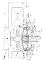
- Fig. 1 shows a top view, for example, as Conveyor belt designed conveyor 1, on which individual, comparatively close to each other Objects 2 are transported in conveying direction A.
- Fig. 1 also shows a conveyor 21, the Direction of conveyance corresponds to the direction of displacement B and thus perpendicular to the conveying direction A of the conveying means 1 runs.
- objects 2 from the funding 1 on the Conveyor 21 can be moved.
- One of the successive objects 2, which in Fig. 1 is shown in broken lines, is in a position in which he is from an inventive Device completely transverse to the direction of conveyance A on the Wegjaner 21 was moved.
- the device according to the invention has a Double lever trained first lever 3, which in Fig. 1 in a first position with solid lines is shown.
- This first lever 3 is perpendicular to one to the drawing level from a main stock 4 ' Defined axis of rotation 4 rotatably supported, the Extension of the axis of rotation 4 by an edge region of the Funding 1 extends.
- the first lever 3 is covered to the intersection of the axis of rotation 4 with the plane of the drawing point symmetrical and tapers with increasing distance from the axis of rotation 4.
- a stationary support arm 5 is also provided, which crosses the outside of the funding area Direction of conveyance A up to the area of the axis of rotation 4 extends, the support arm 5 so far above the Funding 1 is arranged that on the Funding 1 transported objects 2 with the Support arm 5 or other components attached to it device according to the invention collide.
- the main bearing shaft 4 ' is attached, which is the first Lever 3 passes through and on which this around the axis of rotation 4 is rotatably mounted.
- Double lever trained first lever 3 At the two ends of the axis of rotation facing away from the as Double lever trained first lever 3 is a second lever 6, 7 rotatably mounted, the Length extension of the levers 6, 7 about a third of the Distance between the axis of rotation 4 of the first lever 3 and one of those defined by secondary stores 8 ', 9' Axes of rotation 8, 9 of the second lever 6, 7 corresponds. This are associated with attached to the first lever 3 Secondary bearing 8 ', 9' penetrated and rotatable on it stored.
- Lever 3 as double arm lever 3 and the second lever 6, 7 referred to as tabs 6, 7.
- Slider gear 10 is mounted.
- the slide gears 10 are on their underside facing the conveyor 1 in each case with a slider 11, 12 rotatably connected, wherein the slider 11, 12 starting from the slider gears 10 so far down towards the conveyor 1 extend that - unlike the Slider gears 10 - in direct contact with the on objects 2 that are funded 1 can.
- the slides 11, 12 preferably extend close to Funding 1.
- Each of the two slides 11, 12 has a facing the funding area, perpendicular to Contact plane 13 extending the plane of the drawing Extent perpendicular to the plane of the drawing about the height corresponds to the next item 2 to be processed.
- Both sliders 11, 12 each exist from a U-shaped bent metal strip, whereby this U-profiles of the slider 11, 12 in a Open direction of displacement B in the opposite direction.
- Drive mechanism is the double arm lever 3 in Turned clockwise around its axis of rotation 4 while the tabs 6, 7 about their axes of rotation 8, 9 against the Turn clockwise.
- the tabs 6, 7 rotate with respect to the double arm lever 3 three times as fast Axes 8, 9 as the double arm lever 3 around his Rotation axis 4 rotates.
- the tabs 6, 7 a rotation through 540 ° about its axes of rotation 8, 9, while the double arm lever 3 rotates 180 ° around its Axis of rotation 4 executes.
- Fig. 1 three further positions 14 are dot-dashed, 15, 16 shown, which the double arm lever 3, tabs 6, 7, slider gears 10 and sliders 11, 12 take, after the double arm lever 3 starting from its in Fig. 1 position drawn with solid lines Increments of 45 ° clockwise.
- Positions 15 and 16 are then replaced by corresponding further rotations of double lever arm 3, tabs 6, 7 and Slider gears 10 reached, the Double arm lever 3 between successive positions 14, 15 and 16 each turn 45 ° clockwise, while the tabs 6, 7 counterclockwise from Position to position with respect to the double arm lever 3 around turn 135 ° each.
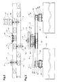
- Fig. 2 shows that along a conveyor line that consists of two funds 1 running parallel to each other consists of several arrangements 17, 18, 19 according to the invention and 20 can be arranged.
- the invention Arrangements 17 and 19 according to FIG. 2 serve to Objects 2 if necessary from a first funding a second funding across to the direction of funding move.
- the arrangement 17 is in a Position where an item has just been moved so that a slider 12 is in its sliding position is while the other slider 11 is straight out moved its retreat position to its home position.
- In the arrangement 19 there is a slide 12 in its retreat position 11 ', while the slide 11 is in its starting position 11 '.
- the arrangement 18 is on the arrangements 17, 19th opposite side of the conveyor line and Accordingly, can serve items 2 from second funding towards the first funding move.
- the arrangement 20, however, is with its axis of rotation 4 Double arm lever 3 in the border area between the two Funding arranged so that this arrangement 20 to do so can serve objects 2 from the first funding to discharge a conveyor 21, i.e. an object 2 from the area of the first and the second funding out move.
- the double arm lever 3 is about the axis of rotation 4 defining main bearing shaft 4 'on the stationary support arm 5 rotatably mounted.
- the double arm lever 3 inner double arm gear 22 connected to it in a rotationally fixed manner on, which together with the double arm lever 3 via a acted upon by a drive motor, not shown Drive toothed belt 23 in a rotating movement around the Axis of rotation 4 is displaceable.
- the double arm gear 22 is located at the top of the double arm lever 3 and is by means of Screws 22 'attached to this.
- the support arm 5 is non-rotatable with a support arm gear 24 connected, which below the double arm lever 3 on the Main bearing 4 'sits and its axis with the The axis of rotation 4 of the double arm lever 3 coincides.
- the double arm lever 3 has at both ends a rotatably mounted about the axes of rotation 8, 9 Tab gear 25, which each with him assigned tab 6, 7 is rotatably connected. If thus the plate gear 25 relative to the double arm lever 3 twisted, the tab 6, 7 is rotated accordingly.
- the tab gear wheels 25 are on secondary bearing shafts 8 ', 9' stored, which are arranged on the double arm lever 3 rotatably and stand out from this towards the bottom.
- the tabs 6, 7 are arranged directly under the plate gears 25.
- the two tab gear wheels 25 have a diameter, which is a third the diameter of the Tragarmiererads 24.
- the two plate gears 25 and that Arm gear 24 are of a common endless Strap toothed belt 26 spanned.
- the double arm lever 3 also has at both ends in each case an outer double arm gear 27, which is non-rotatable connected to it, with the axes of the outer Double arm gears 27 with the axes of rotation 8, 9 of the tabs 6, 7 coincide.
- the outer double arm gears 27 sit underneath the tabs 6 on the Subsidiary stocks 8 'and 9'. Next they are Slider toothed belts 28 each with slider toothed wheels 10 connected, each one and a half times the diameter have, as the outer double arm gears 27.
- Die Slider gears 10 are about the axes of rotation 10 ' rotatably held on the tabs 6, 7, the Slider gears 10 rotatably with the sliders 11, 12 are connected; the latter are the bottom from the Sliding gears 10 screwed.
- In the in Fig. 1 with solid lines are the position shown Contact surfaces 13 of the slider 11, 12 at least approximately in the middle of the tabs 6, 7, thus approximately in the middle between the axes of rotation 8, 9 and the axes 10 '
- the inner double arm gear 22 is located together with the drive toothed belt 23 in a plane below the Support arm 5. Another level lower is the Double arm lever 3. In the level below the Doppelarmhebels 3 are the Tragarmtechnikrad 24, the Tab gear wheels 25 and the tab tooth belt 26. Below the latter level are another Level the tabs 6, 7 arranged, being below the tabs 6,7 still the slide gears 10, the outer Double arm gears 27 and the sliding toothed belts 28 are located. The orders of these levels immediately among themselves leads to an extremely compact and stable construction. The positive power transmission by means of gears and toothed belts leads to an exact quiet operation. Both together make a quick one Operation of the device too.
- the support arm gear 24, the plate gears 25 and the these gears 24, 25 acting together Tab toothed belts 26 form a first gear connection 29 which the tabs 6, 7 depending on the Movement of the double arm lever 3 rotates.
- the drive toothed belt 23 When operating the device according to the invention the drive toothed belt 23 is set in motion so that this over the inner double arm gear 22 den Double arm lever 3 in a rotating movement around the Axis 4 can move. This creates one rotating relative movement between the fixed with the support arm 5 connected support arm gear 24 and the plate gears 25, so that the plate toothed belt 26 the plate gears 25 in a rotating movement about the axes of rotation 8, 9 added. Turn at the same time with the plate gears 25 then the tabs 6, 7 about the axes of rotation 8, 9.
- this preferably deflectable means such as brushes or rags, be attached that stroke over the funding 1 to also thin objects lying on the conveyor 1 2 move.
Landscapes
- Engineering & Computer Science (AREA)
- Mechanical Engineering (AREA)
- Chain Conveyers (AREA)
- Intermediate Stations On Conveyors (AREA)
- Pusher Or Impeller Conveyors (AREA)
- Reciprocating Conveyors (AREA)
- Forklifts And Lifting Vehicles (AREA)
- Automobile Manufacture Line, Endless Track Vehicle, Trailer (AREA)
Abstract
Description
- Fig. 1
- eine Draufsicht auf ein Gegenstände transportierendes Fördermittel mit einer daran montierten möglichen Ausführungsform einer erfindungsgemäßen Vorrichtung,
- Fig. 2
- eine Draufsicht auf eine zwei Fördermittel umfassende Förderstrecke mit vier daran montierten erfindungsgemäßen Vorrichtungen gemäß Fig. 1,
- Fig. 3
- einen Schnitt durch die gesamte Vorrichtung gemäß Fig. 1 in Blickrichtung quer zur Förderrichtung,
- Fig. 4
- eine Seitenansicht einer Vorrichtung gemäß Fig. 1, wobei die Blickrichtung der Förderrichtung entspricht, und
- Fig. 5
- eine teilweise geschnittene Ansicht desjenigen Bereichs der Vorrichtung gemäß den Fig. 1, in dem der Schieber mit dem zweiten Hebel und der zweite Hebel mit dem ersten Hebel verbunden sind.
- dass während einer Verschiebebewegung der Schieber 11, 12 aus ihrer Ausgangsposition 11'' in ihre Verschiebeposition 15 die Laschen 6, 7 jeweils eine 270°-Drehung um ihre Drehachsen 8, 9 ausführen, während der Doppelarmhebel 3 eine 90°-Drehung um seine stationäre Drehachse 4 ausführt,
- dass während einer Rückzugsbewegung der Schieber 11, 12 aus ihrer Verschiebeposition 15 in ihre Rückzugsposition 11' die Laschen 6, 7 jeweils eine 270°-Drehung um ihre Drehachsen 8, 9 ausführen, während der Doppelarmhebel 3 eine 90°-Drehung um seine stationäre Drehachse 4 ausführt,
- dass während der Bewegung der Schieber 11, 12 aus ihrer Rückzugsposition 11' in ihre Ausgangsposition 11'' die Laschen 6, 7 jeweils eine 540°-Drehung um ihre Drehachsen 8, 9 ausführen, während der Doppelarmhebel 3 eine 180°-Drehung um seine stationäre Drehachse 4 ausführt.
- die Schieber 11, 12 eine zu sich parallele Drehlage beibehalten, und
- die Bewegungsbahn des Schiebers 11, 12 einen nahezu gleichseitigen Dreieck mit gerundeten Ecken entspricht.
Claims (13)
- Vorrichtung zum Verschieben von auf einem Fördermittel (1) geförderten Gegenständen mit einem Schieber (11, 12), welcher von einer Antriebseinheit beaufschlagt auf einer vorgegebenen Umlaufbahn umläuft und während des Verschiebevorgangs sowohl mit einer rechtwinklig zur Förderrichtung (A) als auch mit einer in Förderrichtung (A) verlaufenden Bewegungskomponente angetrieben ist, wobei die Antriebseinheit einen um eine Drehachse (4) drehend antreibaren ersten Hebel (3), an dessen der Drehachse (4) abgewandtem Ende ein zweiter Hebel (6, 7) drehbar gelagert ist, der wiederum, an seinem dem ersten Hebel (3) abgewandten Ende, drehbar mit dem Schieber (11, 12) verbunden ist, eine erste Getriebeverbindung (29), welche den zweiten Hebel (6,7) in Abhängigkeit von der Bewegung des ersten Hebels (3) dreht, und eine zwischen dem ersten Hebel (3) und dem Schieber (11,12) wirkende zweite Getriebeverbindung (30), welche den Schieber (11,12) in einer zu sich parallelen Lage hält, aufweist, dadurch gekennzeichnet, dass ein zur Drehachse (4) koaxialer Hauptlagerschaft (4') drehfest an einem Tragarm (5) angeordnet ist, der erste Hebel (3) vom Hauptlagerschaft (4') durchgriffen und drehbar an diesem gehalten ist, ein Nebenlagerschaft (8',9') am ersten Hebel (3) drehfest angeordnet ist, der zweite Hebel (6,7) vom Nebenlagerschaft (8',9') durchgriffen und drehbar an diesem gehalten ist, die erste Getriebeverbindung (29) bezüglich des ersten Hebels (3) auf der dem Tragarm (5) abgewandten Seite angeordnet ist und den Hauptlagerschaft (4') mit dem zweiten Hebel (6,7) verbindet, und die zweite Getriebeverbindung (30) bezüglich des zweiten Hebels (6,7) auf der dem ersten Hebel (3) abgewandten Seite angeordnet ist und den Nebenlagerschaft (8',9') mit dem Schieber (11,12) verbindet.
- Vorrichtung nach Anspruch 1,dadurch gekennzeichnet, dass die erste und die zweite Getriebeverbindung (29,30) durch ein Zahnriemen- oder ein Zahnradgetriebe gebildet sind.
- Vorrichtung nach Anspruch 1 oder 2, dadurch gekennzeichnet, dass der erste Hebel (3) als Doppelarmhebel ausgebildet ist, dessen beide Arme sich in entgegengesetzte Richtungen erstrecken und an ihren der Drehachse (4) abgewandten Enden jeweils einen zweiten Hebel (6, 7) mit Schieber (11, 12). aufweisen.
- Vorrichtung nach Anspruch 3, dadurch gekennzeichnet, dass die den Armen des Doppelarmhebels (3) zugeordneten ersten Getriebeverbindungen (29)ein ihnen gemeinsames, auf dem Hauptlagerschaft (4') drehfest sitzendes Tragarmzahnrad (24) aufweisen.
- Vorrichtung nach einem der Ansprüche 1 bis 4, dadurch gekennzeichnet, dass zwischen dem Tragarm (5) und dem ersten Hebel (3) ein mit diesem ersten Hebel (3) drehfest verbundenes Zahnrad (22) angeordnet ist, das dazu bestimmt ist, von einem Antriebsmotor angetrieben zu sein.
- Vorrichtung nach einem der Ansprüche 1 bis 5, dadurch gekennzeichnet, dass der Schieber (11, 12) derart am zweiten Hebel (6, 7) drehbar gelagert ist, dass sich eine mit dem zu verschiebenden Produkt (2) in Kontakt zu bringende Schieberfläche (13) während der gesamten Umlaufbewegung des Schiebers (11, 12) parallel zur Förderrichtung (A) erstreckt.
- Vorrichtung nach Anspruch 6, dadurch gekennzeichnet, dass die Schieberfläche (13) zu einer Drehachse (10'), um welche der Schieber (11,12) am zweiten Hebel (6,7) drehbar gelagert ist, einen Abstand aufweist, der wenigstens annähernd der halben Länge des zweiten Hebels (6,7) entspricht.
- Vorrichtung nach einem der Ansprüche 1 bis 7,dadurch gekennzeichnet, dass der stationäre Tragarm (5) sich bis in einen Bereich oberhalb des Fördermittels (1) erstreckt, der Schieber (11, 12) unterhalb des ersten und zweiten Hebels (3, 6, 7) angeordnet ist und die Gegenstände (2) mittels des Fördermittels (1) unterhalb dieser Hebel (3, 6, 7) an diesen vorbei förderbar sind.
- Vorrichtung nach einem der Ansprüche 1 bis 8, dadurch gekennzeichnet, dass das untere Ende des Schiebers (11,12), in vertikaler Richtung gesehen, sich nahe beim Fördermittel (1) befindet und vorzugsweise auslenkbare Schiebemittel, wie Bürsten oder Lappen, aufweist, die beim Verschiebevorgang über das Fördermittel (1) streichen, um auch dünne, auf dem Fördermittel (1) aufliegende Gegenstände (2) zu verschieben.
- Vorrichtung nach einem der Ansprüche 1 bis 9,dadurch gekennzeichnet, dass die Hebel (3, 6, 7) und der Schieber (11, 12) intermittierend angetrieben sind.
- Vorrichtung nach einem der Ansprüche 1 bis 10, dadurch gekennzeichnet, dass der Schieber (11, 12) zum Verschieben eines Produktes (2) aus einer Ausgangsposition (11") durch den Förderbereich des Fördermittels (1) in eine das Ende des Verschiebevorgangs kennzeichnende Verschiebeposition (15), nach dem Verschiebevorgang aus seiner Verschiebeposition (15) in eine außerhalb des Förderbereichs gelegene Rückzugsposition (11'), und anschließend außerhalb des Förderbereichs aus seiner Rückzugsposition (11') wieder in seine Ausgangsposition (11") bewegbar ist, bei der Verschiebebewegung und bei der Bewegung des Schiebers (11, 12) in die Rückzugsposition (11') die Größe der parallel zur Förderrichtung (A) verlaufenden Bewegungskomponente des Schiebers (11, 12) zumindest im Wesentlichen gleich der Fördergeschwindigkeit des Fördermittels (1) ist und die Umlaufbahn im Wesentlichen ein gleichseitiges Dreieck bildet.
- Vorrichtung nach einem der Ansprüche 1 bis 11, dadurch gekennzeichnet, dass die Hebel (3, 6, 7) derart angetrieben sind, dass der zweite Hebel (6, 7) nach Verlassen der Ausgangsposition in Richtung der Drehachse (4) des ersten Hebels (3) schwenkt.
- Vorrichtung nach einem der Ansprüche 1 bis 12, dadurch gekennzeichnet, dass der zweite Hebel (6, 7) eine 540°-Drehung um seine am Ende des ersten Hebels (3) befindliche Drehachse (8, 9) ausführt, während der erste Hebel (3) eine 180°-Drehung um seine stationäre Drehachse (4) ausführt.
Applications Claiming Priority (2)
| Application Number | Priority Date | Filing Date | Title |
|---|---|---|---|
| CH16962002 | 2002-10-11 | ||
| CH16962002 | 2002-10-11 |
Publications (2)
| Publication Number | Publication Date |
|---|---|
| EP1407991A1 true EP1407991A1 (de) | 2004-04-14 |
| EP1407991B1 EP1407991B1 (de) | 2006-07-12 |
Family
ID=32000119
Family Applications (1)
| Application Number | Title | Priority Date | Filing Date |
|---|---|---|---|
| EP03019108A Expired - Lifetime EP1407991B1 (de) | 2002-10-11 | 2003-08-23 | Vorrichtung zum Verschieben von auf einem Fördermittel geförderten Gegenständen |
Country Status (4)
| Country | Link |
|---|---|
| EP (1) | EP1407991B1 (de) |
| AT (1) | ATE332860T1 (de) |
| DE (1) | DE50304197D1 (de) |
| DK (1) | DK1407991T3 (de) |
Cited By (1)
| Publication number | Priority date | Publication date | Assignee | Title |
|---|---|---|---|---|
| CN108860841A (zh) * | 2017-12-01 | 2018-11-23 | 瑞光(上海)电气设备有限公司 | 一种产品推送装置 |
Citations (6)
| Publication number | Priority date | Publication date | Assignee | Title |
|---|---|---|---|---|
| US3212623A (en) * | 1961-10-27 | 1965-10-19 | Earl G Griffith | Conveyor delivery system |
| JPS5665712A (en) | 1979-10-30 | 1981-06-03 | Anritsu Corp | Assortment device |
| EP0182938A1 (de) * | 1984-10-31 | 1986-06-04 | Masyc AG | Umsetzer für Stückgutförderer |
| EP0532978A1 (de) | 1991-09-18 | 1993-03-24 | Günter Rexing | Kastenausstossvorrichtung |
| EP0659665A1 (de) * | 1993-12-23 | 1995-06-28 | P.R.B. Packaging Systems S.R.L. | Vorrichtung zum kontinuierlichen Zuführen von Stückgutteilen von einem Hauptförderer zu Zwischenabführkanälen, Schräg angestellt in Bezug auf den Hauptförderer |
| EP0853057A1 (de) * | 1997-01-11 | 1998-07-15 | AMI Förder- und Lagertechnik GmbH | Vorrichtung zum Befördern eines von einer Transportvorrichtung in einer Transportrichtung bewegten Gegenstandes quer zur Transportrichtung |
-
2003
- 2003-08-23 EP EP03019108A patent/EP1407991B1/de not_active Expired - Lifetime
- 2003-08-23 DK DK03019108T patent/DK1407991T3/da active
- 2003-08-23 DE DE50304197T patent/DE50304197D1/de not_active Expired - Lifetime
- 2003-08-23 AT AT03019108T patent/ATE332860T1/de not_active IP Right Cessation
Patent Citations (6)
| Publication number | Priority date | Publication date | Assignee | Title |
|---|---|---|---|---|
| US3212623A (en) * | 1961-10-27 | 1965-10-19 | Earl G Griffith | Conveyor delivery system |
| JPS5665712A (en) | 1979-10-30 | 1981-06-03 | Anritsu Corp | Assortment device |
| EP0182938A1 (de) * | 1984-10-31 | 1986-06-04 | Masyc AG | Umsetzer für Stückgutförderer |
| EP0532978A1 (de) | 1991-09-18 | 1993-03-24 | Günter Rexing | Kastenausstossvorrichtung |
| EP0659665A1 (de) * | 1993-12-23 | 1995-06-28 | P.R.B. Packaging Systems S.R.L. | Vorrichtung zum kontinuierlichen Zuführen von Stückgutteilen von einem Hauptförderer zu Zwischenabführkanälen, Schräg angestellt in Bezug auf den Hauptförderer |
| EP0853057A1 (de) * | 1997-01-11 | 1998-07-15 | AMI Förder- und Lagertechnik GmbH | Vorrichtung zum Befördern eines von einer Transportvorrichtung in einer Transportrichtung bewegten Gegenstandes quer zur Transportrichtung |
Cited By (2)
| Publication number | Priority date | Publication date | Assignee | Title |
|---|---|---|---|---|
| CN108860841A (zh) * | 2017-12-01 | 2018-11-23 | 瑞光(上海)电气设备有限公司 | 一种产品推送装置 |
| CN108860841B (zh) * | 2017-12-01 | 2024-01-16 | 瑞光(上海)电气设备有限公司 | 一种产品推送装置 |
Also Published As
| Publication number | Publication date |
|---|---|
| DK1407991T3 (da) | 2006-08-14 |
| ATE332860T1 (de) | 2006-08-15 |
| DE50304197D1 (de) | 2006-08-24 |
| EP1407991B1 (de) | 2006-07-12 |
Similar Documents
| Publication | Publication Date | Title |
|---|---|---|
| DD200850A5 (de) | Uebertragungsvorrichtung fuer staebchenfoermige artikel | |
| DE1284354B (de) | Vorrichtung zum Umsetzen von Gegenstaenden | |
| EP0345585B1 (de) | Fördervorrichtung für Süsswarenstücke | |
| DE2205153A1 (de) | Transportstrecke zum transportieren von werkstueckpaketen fuer die sackfertigung | |
| EP3366614B1 (de) | Zufuhrketten-einheit | |
| EP1042206B1 (de) | Vorrichtung zum aufnehmen und/oder abgeben flächiger erzeugnisse | |
| EP1571130A2 (de) | Verfahren und Vorrichtung zum Überschieben von Hohlglasgegenständen aus einer Glasformmaschine auf ein Transportband | |
| DE4439728A1 (de) | Vorrichtung zum Befördern und Gruppieren von Gegenständen | |
| DE2756417A1 (de) | Transporteinrichtung, insbesondere fuer die schrittweise befoerderung von werkstuecken bei pressen | |
| EP0283670A2 (de) | Gruppiereinrichtung zur Bildung von Behältergruppen | |
| EP0919473A1 (de) | Vorrichtung zum Verschliessen von schlauch- oder beutelförmigen Verpackungshüllen | |
| DE2620036A1 (de) | Abstreifeinrichtung fuer foerderbaender | |
| DE69507927T2 (de) | Vorrichtung zur Verschieben eines Produktes | |
| DE3324984A1 (de) | Vorrichtung zum einwickeln von bonbons | |
| DE202009009007U1 (de) | Sortierförderer mit Doppeltragschale | |
| EP1407991B1 (de) | Vorrichtung zum Verschieben von auf einem Fördermittel geförderten Gegenständen | |
| DE19755204A1 (de) | Förderanlage | |
| DE4224566A1 (de) | Austrag-foerderereinheit fuer verpackungsmaschinen | |
| DE2855088C2 (de) | ||
| EP0903308B1 (de) | Zellenrad zur Uebergabe von Gegenständen von einem ersten Fördermittel an ein zweites Fördermittel | |
| EP0999161B1 (de) | Vorrichtung zum Ausgleich der Vorschubbewegung einer Folienbahn | |
| DE19943759C1 (de) | Einrichtung zur Handhabung blattartiger Gegenstände, insbesondere zum Zufördern von Kuverts zu einer Kuvertierstation | |
| DE2735364C3 (de) | Vorrichtung zum vereinzelten Herabschieben von Gegenständen von einem endlosen Förderer | |
| DE3107500C2 (de) | Fördervorrichtung | |
| EP0829441B1 (de) | Vorrichtung zum Ausstossen gestapelter Druckbogen |
Legal Events
| Date | Code | Title | Description |
|---|---|---|---|
| PUAI | Public reference made under article 153(3) epc to a published international application that has entered the european phase |
Free format text: ORIGINAL CODE: 0009012 |
|
| 17P | Request for examination filed |
Effective date: 20040205 |
|
| AK | Designated contracting states |
Kind code of ref document: A1 Designated state(s): AT BE BG CH CY CZ DE DK EE ES FI FR GB GR HU IE IT LI LU MC NL PT RO SE SI SK TR |
|
| AX | Request for extension of the european patent |
Extension state: AL LT LV MK |
|
| AKX | Designation fees paid |
Designated state(s): AT BE BG CH CY CZ DE DK EE ES FI FR GB GR HU IE IT LI LU MC NL PT RO SE SI SK TR |
|
| GRAP | Despatch of communication of intention to grant a patent |
Free format text: ORIGINAL CODE: EPIDOSNIGR1 |
|
| RTI1 | Title (correction) |
Free format text: DEVICE FOR PUSHING OF ARTICLES LYING ON A CONVEYOR |
|
| GRAS | Grant fee paid |
Free format text: ORIGINAL CODE: EPIDOSNIGR3 |
|
| GRAA | (expected) grant |
Free format text: ORIGINAL CODE: 0009210 |
|
| AK | Designated contracting states |
Kind code of ref document: B1 Designated state(s): AT BE BG CH CY CZ DE DK EE ES FI FR GB GR HU IE IT LI LU MC NL PT RO SE SI SK TR |
|
| PG25 | Lapsed in a contracting state [announced via postgrant information from national office to epo] |
Ref country code: IT Free format text: LAPSE BECAUSE OF FAILURE TO SUBMIT A TRANSLATION OF THE DESCRIPTION OR TO PAY THE FEE WITHIN THE PRESCRIBED TIME-LIMIT;WARNING: LAPSES OF ITALIAN PATENTS WITH EFFECTIVE DATE BEFORE 2007 MAY HAVE OCCURRED AT ANY TIME BEFORE 2007. THE CORRECT EFFECTIVE DATE MAY BE DIFFERENT FROM THE ONE RECORDED. Effective date: 20060712 Ref country code: RO Free format text: LAPSE BECAUSE OF FAILURE TO SUBMIT A TRANSLATION OF THE DESCRIPTION OR TO PAY THE FEE WITHIN THE PRESCRIBED TIME-LIMIT Effective date: 20060712 Ref country code: IE Free format text: LAPSE BECAUSE OF FAILURE TO SUBMIT A TRANSLATION OF THE DESCRIPTION OR TO PAY THE FEE WITHIN THE PRESCRIBED TIME-LIMIT Effective date: 20060712 Ref country code: NL Free format text: LAPSE BECAUSE OF FAILURE TO SUBMIT A TRANSLATION OF THE DESCRIPTION OR TO PAY THE FEE WITHIN THE PRESCRIBED TIME-LIMIT Effective date: 20060712 Ref country code: SI Free format text: LAPSE BECAUSE OF FAILURE TO SUBMIT A TRANSLATION OF THE DESCRIPTION OR TO PAY THE FEE WITHIN THE PRESCRIBED TIME-LIMIT Effective date: 20060712 Ref country code: CZ Free format text: LAPSE BECAUSE OF FAILURE TO SUBMIT A TRANSLATION OF THE DESCRIPTION OR TO PAY THE FEE WITHIN THE PRESCRIBED TIME-LIMIT Effective date: 20060712 Ref country code: GB Free format text: LAPSE BECAUSE OF FAILURE TO SUBMIT A TRANSLATION OF THE DESCRIPTION OR TO PAY THE FEE WITHIN THE PRESCRIBED TIME-LIMIT Effective date: 20060712 Ref country code: SK Free format text: LAPSE BECAUSE OF FAILURE TO SUBMIT A TRANSLATION OF THE DESCRIPTION OR TO PAY THE FEE WITHIN THE PRESCRIBED TIME-LIMIT Effective date: 20060712 |
|
| REG | Reference to a national code |
Ref country code: GB Ref legal event code: FG4D Free format text: NOT ENGLISH |
|
| REG | Reference to a national code |
Ref country code: CH Ref legal event code: EP |
|
| REG | Reference to a national code |
Ref country code: CH Ref legal event code: NV Representative=s name: PATENTANWAELTE SCHAAD, BALASS, MENZL & PARTNER AG |
|
| REG | Reference to a national code |
Ref country code: DK Ref legal event code: T3 |
|
| REG | Reference to a national code |
Ref country code: IE Ref legal event code: FG4D Free format text: LANGUAGE OF EP DOCUMENT: GERMAN |
|
| REF | Corresponds to: |
Ref document number: 50304197 Country of ref document: DE Date of ref document: 20060824 Kind code of ref document: P |
|
| PG25 | Lapsed in a contracting state [announced via postgrant information from national office to epo] |
Ref country code: MC Free format text: LAPSE BECAUSE OF NON-PAYMENT OF DUE FEES Effective date: 20060831 Ref country code: BE Free format text: LAPSE BECAUSE OF NON-PAYMENT OF DUE FEES Effective date: 20060831 |
|
| PG25 | Lapsed in a contracting state [announced via postgrant information from national office to epo] |
Ref country code: BG Free format text: LAPSE BECAUSE OF FAILURE TO SUBMIT A TRANSLATION OF THE DESCRIPTION OR TO PAY THE FEE WITHIN THE PRESCRIBED TIME-LIMIT Effective date: 20061012 Ref country code: SE Free format text: LAPSE BECAUSE OF FAILURE TO SUBMIT A TRANSLATION OF THE DESCRIPTION OR TO PAY THE FEE WITHIN THE PRESCRIBED TIME-LIMIT Effective date: 20061012 |
|
| PG25 | Lapsed in a contracting state [announced via postgrant information from national office to epo] |
Ref country code: ES Free format text: LAPSE BECAUSE OF FAILURE TO SUBMIT A TRANSLATION OF THE DESCRIPTION OR TO PAY THE FEE WITHIN THE PRESCRIBED TIME-LIMIT Effective date: 20061023 |
|
| PG25 | Lapsed in a contracting state [announced via postgrant information from national office to epo] |
Ref country code: PT Free format text: LAPSE BECAUSE OF FAILURE TO SUBMIT A TRANSLATION OF THE DESCRIPTION OR TO PAY THE FEE WITHIN THE PRESCRIBED TIME-LIMIT Effective date: 20061212 |
|
| NLV1 | Nl: lapsed or annulled due to failure to fulfill the requirements of art. 29p and 29m of the patents act | ||
| GBV | Gb: ep patent (uk) treated as always having been void in accordance with gb section 77(7)/1977 [no translation filed] |
Effective date: 20060712 |
|
| REG | Reference to a national code |
Ref country code: IE Ref legal event code: FD4D |
|
| EN | Fr: translation not filed | ||
| PLBE | No opposition filed within time limit |
Free format text: ORIGINAL CODE: 0009261 |
|
| STAA | Information on the status of an ep patent application or granted ep patent |
Free format text: STATUS: NO OPPOSITION FILED WITHIN TIME LIMIT |
|
| 26N | No opposition filed |
Effective date: 20070413 |
|
| PG25 | Lapsed in a contracting state [announced via postgrant information from national office to epo] |
Ref country code: AT Free format text: LAPSE BECAUSE OF NON-PAYMENT OF DUE FEES Effective date: 20060823 |
|
| BERE | Be: lapsed |
Owner name: FERAG AG Effective date: 20060831 |
|
| PG25 | Lapsed in a contracting state [announced via postgrant information from national office to epo] |
Ref country code: GR Free format text: LAPSE BECAUSE OF FAILURE TO SUBMIT A TRANSLATION OF THE DESCRIPTION OR TO PAY THE FEE WITHIN THE PRESCRIBED TIME-LIMIT Effective date: 20061013 Ref country code: FR Free format text: LAPSE BECAUSE OF FAILURE TO SUBMIT A TRANSLATION OF THE DESCRIPTION OR TO PAY THE FEE WITHIN THE PRESCRIBED TIME-LIMIT Effective date: 20070511 |
|
| PG25 | Lapsed in a contracting state [announced via postgrant information from national office to epo] |
Ref country code: EE Free format text: LAPSE BECAUSE OF FAILURE TO SUBMIT A TRANSLATION OF THE DESCRIPTION OR TO PAY THE FEE WITHIN THE PRESCRIBED TIME-LIMIT Effective date: 20060712 |
|
| PG25 | Lapsed in a contracting state [announced via postgrant information from national office to epo] |
Ref country code: LU Free format text: LAPSE BECAUSE OF NON-PAYMENT OF DUE FEES Effective date: 20060823 Ref country code: HU Free format text: LAPSE BECAUSE OF FAILURE TO SUBMIT A TRANSLATION OF THE DESCRIPTION OR TO PAY THE FEE WITHIN THE PRESCRIBED TIME-LIMIT Effective date: 20070113 Ref country code: TR Free format text: LAPSE BECAUSE OF FAILURE TO SUBMIT A TRANSLATION OF THE DESCRIPTION OR TO PAY THE FEE WITHIN THE PRESCRIBED TIME-LIMIT Effective date: 20060712 |
|
| PG25 | Lapsed in a contracting state [announced via postgrant information from national office to epo] |
Ref country code: FR Free format text: LAPSE BECAUSE OF FAILURE TO SUBMIT A TRANSLATION OF THE DESCRIPTION OR TO PAY THE FEE WITHIN THE PRESCRIBED TIME-LIMIT Effective date: 20060712 Ref country code: CY Free format text: LAPSE BECAUSE OF FAILURE TO SUBMIT A TRANSLATION OF THE DESCRIPTION OR TO PAY THE FEE WITHIN THE PRESCRIBED TIME-LIMIT Effective date: 20060712 |
|
| PGFP | Annual fee paid to national office [announced via postgrant information from national office to epo] |
Ref country code: DK Payment date: 20110822 Year of fee payment: 9 |
|
| PGFP | Annual fee paid to national office [announced via postgrant information from national office to epo] |
Ref country code: FI Payment date: 20120813 Year of fee payment: 10 |
|
| REG | Reference to a national code |
Ref country code: DK Ref legal event code: EBP Effective date: 20130831 |
|
| PG25 | Lapsed in a contracting state [announced via postgrant information from national office to epo] |
Ref country code: FI Free format text: LAPSE BECAUSE OF NON-PAYMENT OF DUE FEES Effective date: 20130823 |
|
| PG25 | Lapsed in a contracting state [announced via postgrant information from national office to epo] |
Ref country code: DK Free format text: LAPSE BECAUSE OF NON-PAYMENT OF DUE FEES Effective date: 20130831 |
|
| PGFP | Annual fee paid to national office [announced via postgrant information from national office to epo] |
Ref country code: DE Payment date: 20150821 Year of fee payment: 13 |
|
| PGFP | Annual fee paid to national office [announced via postgrant information from national office to epo] |
Ref country code: CH Payment date: 20151028 Year of fee payment: 13 |
|
| REG | Reference to a national code |
Ref country code: DE Ref legal event code: R119 Ref document number: 50304197 Country of ref document: DE |
|
| REG | Reference to a national code |
Ref country code: CH Ref legal event code: PL |
|
| PG25 | Lapsed in a contracting state [announced via postgrant information from national office to epo] |
Ref country code: CH Free format text: LAPSE BECAUSE OF NON-PAYMENT OF DUE FEES Effective date: 20160831 Ref country code: LI Free format text: LAPSE BECAUSE OF NON-PAYMENT OF DUE FEES Effective date: 20160831 |
|
| PG25 | Lapsed in a contracting state [announced via postgrant information from national office to epo] |
Ref country code: DE Free format text: LAPSE BECAUSE OF NON-PAYMENT OF DUE FEES Effective date: 20170301 |