EP1407151B1 - Procede de fabrication d'un dispositif de commande par cable sous gaine et dispositif de commande obtenu par ce procede - Google Patents
Procede de fabrication d'un dispositif de commande par cable sous gaine et dispositif de commande obtenu par ce procede Download PDFInfo
- Publication number
- EP1407151B1 EP1407151B1 EP02780919A EP02780919A EP1407151B1 EP 1407151 B1 EP1407151 B1 EP 1407151B1 EP 02780919 A EP02780919 A EP 02780919A EP 02780919 A EP02780919 A EP 02780919A EP 1407151 B1 EP1407151 B1 EP 1407151B1
- Authority
- EP
- European Patent Office
- Prior art keywords
- sheath
- cable
- shaping
- heat
- thermoplastic material
- Prior art date
- Legal status (The legal status is an assumption and is not a legal conclusion. Google has not performed a legal analysis and makes no representation as to the accuracy of the status listed.)
- Expired - Lifetime
Links
- 238000000034 method Methods 0.000 title claims abstract description 17
- 239000012815 thermoplastic material Substances 0.000 claims abstract description 14
- 238000004519 manufacturing process Methods 0.000 claims abstract description 13
- 238000005520 cutting process Methods 0.000 claims abstract description 9
- 238000001125 extrusion Methods 0.000 claims abstract description 8
- 238000004873 anchoring Methods 0.000 claims abstract description 6
- 239000000463 material Substances 0.000 claims abstract description 6
- 229920002994 synthetic fiber Polymers 0.000 claims abstract description 5
- 239000004698 Polyethylene Substances 0.000 claims description 3
- -1 polyethylene Polymers 0.000 claims description 3
- 229920000573 polyethylene Polymers 0.000 claims description 3
- 238000007493 shaping process Methods 0.000 claims 7
- 229920012196 Polyoxymethylene Copolymer Polymers 0.000 claims 1
- 229920009382 Polyoxymethylene Homopolymer Polymers 0.000 claims 1
- 230000002093 peripheral effect Effects 0.000 claims 1
- 238000003856 thermoforming Methods 0.000 abstract description 8
- 239000004033 plastic Substances 0.000 description 3
- 229920003023 plastic Polymers 0.000 description 3
- 241000735470 Juncus Species 0.000 description 2
- 229930040373 Paraformaldehyde Natural products 0.000 description 2
- 238000010438 heat treatment Methods 0.000 description 2
- 238000002347 injection Methods 0.000 description 2
- 239000007924 injection Substances 0.000 description 2
- 229920006324 polyoxymethylene Polymers 0.000 description 2
- 238000004378 air conditioning Methods 0.000 description 1
- 230000015572 biosynthetic process Effects 0.000 description 1
- 238000004140 cleaning Methods 0.000 description 1
- 229920001577 copolymer Polymers 0.000 description 1
- 229920001519 homopolymer Polymers 0.000 description 1
- 239000002184 metal Substances 0.000 description 1
- 238000000465 moulding Methods 0.000 description 1
- 239000004753 textile Substances 0.000 description 1
- 229920001169 thermoplastic Polymers 0.000 description 1
- 239000004416 thermosoftening plastic Substances 0.000 description 1
Images
Classifications
-
- F—MECHANICAL ENGINEERING; LIGHTING; HEATING; WEAPONS; BLASTING
- F16—ENGINEERING ELEMENTS AND UNITS; GENERAL MEASURES FOR PRODUCING AND MAINTAINING EFFECTIVE FUNCTIONING OF MACHINES OR INSTALLATIONS; THERMAL INSULATION IN GENERAL
- F16C—SHAFTS; FLEXIBLE SHAFTS; ELEMENTS OR CRANKSHAFT MECHANISMS; ROTARY BODIES OTHER THAN GEARING ELEMENTS; BEARINGS
- F16C1/00—Flexible shafts; Mechanical means for transmitting movement in a flexible sheathing
- F16C1/10—Means for transmitting linear movement in a flexible sheathing, e.g. "Bowden-mechanisms"
- F16C1/20—Construction of flexible members moved to and fro in the sheathing
-
- F—MECHANICAL ENGINEERING; LIGHTING; HEATING; WEAPONS; BLASTING
- F16—ENGINEERING ELEMENTS AND UNITS; GENERAL MEASURES FOR PRODUCING AND MAINTAINING EFFECTIVE FUNCTIONING OF MACHINES OR INSTALLATIONS; THERMAL INSULATION IN GENERAL
- F16C—SHAFTS; FLEXIBLE SHAFTS; ELEMENTS OR CRANKSHAFT MECHANISMS; ROTARY BODIES OTHER THAN GEARING ELEMENTS; BEARINGS
- F16C1/00—Flexible shafts; Mechanical means for transmitting movement in a flexible sheathing
- F16C1/10—Means for transmitting linear movement in a flexible sheathing, e.g. "Bowden-mechanisms"
-
- F—MECHANICAL ENGINEERING; LIGHTING; HEATING; WEAPONS; BLASTING
- F16—ENGINEERING ELEMENTS AND UNITS; GENERAL MEASURES FOR PRODUCING AND MAINTAINING EFFECTIVE FUNCTIONING OF MACHINES OR INSTALLATIONS; THERMAL INSULATION IN GENERAL
- F16C—SHAFTS; FLEXIBLE SHAFTS; ELEMENTS OR CRANKSHAFT MECHANISMS; ROTARY BODIES OTHER THAN GEARING ELEMENTS; BEARINGS
- F16C1/00—Flexible shafts; Mechanical means for transmitting movement in a flexible sheathing
- F16C1/26—Construction of guiding-sheathings or guiding-tubes
Definitions
- the present invention relates to the field of devices for control of the type comprising a flexible cable sliding in a flexible sheath, the ends of said sheath and of the cable can be fixed in a removable way.
- Such control devices usually called cables “Bowden”, have multiple applications for example in the automobile for controlling air conditioning flaps or heating, or in the building to control a drain valve of a sanitary appliance.
- the cable is metallic and the sheath is wire metallic wound with contiguous turns, possibly coated in a textile or plastic outer film.
- These devices known control devices are heavy and expensive and difficult to to recycle . In addition, they are poorly resistant to environments aggressive, for example a humid atmosphere.
- the present invention therefore aims to overcome the disadvantages of cable control devices under all-plastic sheath known through a manufacturing process making it possible to obtain, very economically, pre-assembled control devices of dimensions variables.
- the method according to the invention offers the advantage of allowing to get a pre-assembled control device, starting of components (extruded tube and extruded rod) very economical, cutting, assembly and formation of the means of fixing the sheath and the cable can be easily automated with cycle times short.
- the invention relates to a device for cable control under sheath, said sheath and said cable being of synthetic material and being provided with their two ends of fasteners, manufactured by the process previous, characterized in that the fasteners are in one piece respectively with the sheath and with the cable.
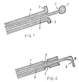
- the control device consists of a sheath 1 of thermoplastic material in which a cable 2 also slides in thermoplastic material.
- the sheath 1 is constituted by a portion cut from a extruded tube in thermoplastic material. At each end of the tube is formed a fixing stop 3 which has been obtained either by hot forming of an end flange 4 (Figure 1) in a mold or by hot forming a groove device 5 (figure 2) or notches (embodiment not shown), or by removing material from the sheath.
- Cable 2 is formed by a portion of a rod extruded in thermoplastic material at the ends of which is formed an anchoring projection 6 which is obtained by molding hot of a sphere 7 ( Figure 1) or a lens or a cylinder, by hot folding of one end 8 of the cable 2 ( Figure 2) or by any other hot deformation process to obtain a projection suitable for fixing the cable 2.
- the sheath 1 is provided, preferably before introduction of the cable 2, of its fixing stops 3 by an operation of thermoforming or material removal, as shown previously.
- the notches could have been spared serving as a fixing stop, by thermoforming or by removal of material from the tube before cutting into sheath sections.
- the cable 2 being introduced into the sheath 1 and its ends protruding from the sheath 1, cleaning on each of the ends protruding from the anchoring projection 6 also by a thermoforming operation.
- This operation can be performed simultaneously with thermoforming of the stops fixing 3 of the sheath 1, by simultaneous heating of the adjacent ends of sheath 1 and cable 2.
- thermoplastic materials of the sheath 1 and of the cable 2 can be the same, but they are preferably different for reduced friction and optimal mechanical resistance.
- PE polyethylene
- POM homo or copolymer polyoxymethylene
Landscapes
- Engineering & Computer Science (AREA)
- General Engineering & Computer Science (AREA)
- Oral & Maxillofacial Surgery (AREA)
- Mechanical Engineering (AREA)
- Health & Medical Sciences (AREA)
- Flexible Shafts (AREA)
- Extrusion Moulding Of Plastics Or The Like (AREA)
- Insulated Conductors (AREA)
- Electrophonic Musical Instruments (AREA)
- Air Bags (AREA)
- Ropes Or Cables (AREA)
- Cable Accessories (AREA)
- Communication Cables (AREA)
Description
- fabrication par extrusion d'un tube de grande longueur en matière thermoplastique,
- fabrication par extrusion d'un jonc de grande longueur en matière thermoplastique,
- coupe du tube en éléments de gaine de longueur prédéterminée,
- coupe du jonc en éléments de câble de longueur prédéterminée,
- thermoformage ou formage par enlèvement de matière d'une butée de fixation à chaque extrémité des éléments de gaine,
- introduction d'un élément de câble à l'intérieur d'un élément de gaine,
- coulissement de l'élément de câble à l'intérieur de l'élément de gaine jusqu'à ce qu'il fasse saillie par rapport aux deux extrémités de l'élément de gaine et
- thermoformage d'une saillie d'ancrage à chaque extrémité saillante de l'élément de câble.
Claims (10)
- Procédé de fabrication d'un dispositif de commande par câble sous gaine, ladite gaine et ledit câble étant en matière synthétique et étant munis à leurs deux extrémités d'organes de fixation,
caractérisé par les étapes suivantes :fabrication par extrusion d'un tube de grande longueur en matière thermoplastique,fabrication par extrusion d'un jonc de grande longueur en matière thermoplastique,coupe du tube en éléments de gaine (1) de longueur prédéterminée,coupe du jonc en éléments de câble (2) de longueur prédéterminée,thermoformage ou formage par enlèvement de matière d'une butée de fixation (3) à chaque extrémité des éléments de gaine (1),introduction d'un élément de câble (2) à l'intérieur d'un élément de gaine (1),coulissement de l'élément de câble (2) à l'intérieur de l'élément de gaine (1) jusqu'à ce qu'il fasse saillie par rapport aux deux extrémités de l'élément de gaine (1) etthermoformage d'une saillie d'ancrage (6) à chaque extrémité saillante de l'élément de câble (2). - Procédé selon la revendication 1,
caractérisé en ce que le thermoformage des butées de fixation (3) sur l'élément de gaine (1) est effectué avant l'introduction de l'élément de câble (2). - Procédé selon la revendication 1,
caractérisé en ce que le thermoformage des butées de fixation (3) sur l'élément de gaine (1) est effectué après l'introduction de l'élément de câble (2). - Procédé selon la revendication 3,
caractérisé en ce que le thermoformage des butées de fixation (3) sur l'élément de gaine (1) et le thermoformage des saillies d'ancrage (6) sur l'élément de câble (2) sont effectués simultanément. - Procédé selon l'une des revendications 1 à 4,
caractérisé en ce que les butées de fixation (3) de la gaine (1) ont la forme de collerettes d'extrémité (4). - Procédé selon l'une des revendications 1 à 4,
caractérisé en ce que les butées de fixation (3) de la gaine (1) ont la forme de rainures périphériques (5) ou d'encoches. - Procédé selon l'une des revendications 1 à 6,
caractérisé en ce que les saillies d'extrémité (6) du câble (2) ont la forme d'une sphère (7) d'une lentille ou d'un cylindre. - Procédé selon l'une des revendications 1 à 6,
caractérisé en ce que les saillies d'extrémité (6) du câble (2) ont la forme d'une extrémité repliée (8). - Procédé selon l'une des revendications 1 à 8,
caractérisé en ce que la matière thermoplastique de la gaine (1) est du polyéthylène. - Procédé selon l'une des revendications 1 à 9,
caractérisé en ce que la matière thermoplastique du câble (2) est du polyoxyméthylène homo ou copolymère.
Applications Claiming Priority (3)
| Application Number | Priority Date | Filing Date | Title |
|---|---|---|---|
| FR0108621A FR2826699B1 (fr) | 2001-06-29 | 2001-06-29 | Procede de fabrication d'un dispositif de commande par cable sous gaine et dispositif de commande obtenu par ce procede |
| FR0108621 | 2001-06-29 | ||
| PCT/FR2002/002245 WO2003002881A1 (fr) | 2001-06-29 | 2002-06-28 | Procede de fabrication d'un dispositif de commande par câble sous gaine et dispositif de commande obtenu par ce procede |
Publications (2)
| Publication Number | Publication Date |
|---|---|
| EP1407151A1 EP1407151A1 (fr) | 2004-04-14 |
| EP1407151B1 true EP1407151B1 (fr) | 2004-11-10 |
Family
ID=8864929
Family Applications (1)
| Application Number | Title | Priority Date | Filing Date |
|---|---|---|---|
| EP02780919A Expired - Lifetime EP1407151B1 (fr) | 2001-06-29 | 2002-06-28 | Procede de fabrication d'un dispositif de commande par cable sous gaine et dispositif de commande obtenu par ce procede |
Country Status (7)
| Country | Link |
|---|---|
| EP (1) | EP1407151B1 (fr) |
| AT (1) | ATE282153T1 (fr) |
| DE (1) | DE60201913T2 (fr) |
| ES (1) | ES2232781T3 (fr) |
| FR (1) | FR2826699B1 (fr) |
| PT (1) | PT1407151E (fr) |
| WO (1) | WO2003002881A1 (fr) |
Cited By (1)
| Publication number | Priority date | Publication date | Assignee | Title |
|---|---|---|---|---|
| EP2058557A4 (fr) * | 2006-08-31 | 2010-04-21 | Toyota Boshoku Kk | Structure de connexion de câble |
Family Cites Families (7)
| Publication number | Priority date | Publication date | Assignee | Title |
|---|---|---|---|---|
| US3434501A (en) * | 1967-02-13 | 1969-03-25 | Teleflex Inc | Motion transmitting remote control assembly |
| US3657942A (en) | 1970-06-09 | 1972-04-25 | Matthew A Sullivan | Control cable |
| DE2032959A1 (en) * | 1970-07-03 | 1972-01-13 | Ver Deutsche Metallwerke Ag | Plastics guide tube - for 'bowden' cable |
| US4099425A (en) * | 1976-06-01 | 1978-07-11 | Samuel Moore And Company | Method of making push-pull cable conduit and product |
| EP0438745A1 (fr) * | 1990-01-05 | 1991-07-31 | Orscheln Co. | Gaine flexible résistant à la corrosion et procédé pour sa fabrication |
| CH682837A5 (de) * | 1991-03-19 | 1993-11-30 | Belinox Ag | Bowdenzug für Ventilbetätigung an einem Sanitär-Ablaufventil und Verfahren zu seiner Herstellung. |
| MX9203982A (es) * | 1991-08-30 | 1993-02-01 | Xerox Corp | Conjunto de eje impulsor, flexible, moldeado de una sola pieza. |
-
2001
- 2001-06-29 FR FR0108621A patent/FR2826699B1/fr not_active Expired - Fee Related
-
2002
- 2002-06-28 WO PCT/FR2002/002245 patent/WO2003002881A1/fr not_active Ceased
- 2002-06-28 DE DE60201913T patent/DE60201913T2/de not_active Expired - Fee Related
- 2002-06-28 EP EP02780919A patent/EP1407151B1/fr not_active Expired - Lifetime
- 2002-06-28 PT PT02780919T patent/PT1407151E/pt unknown
- 2002-06-28 ES ES02780919T patent/ES2232781T3/es not_active Expired - Lifetime
- 2002-06-28 AT AT02780919T patent/ATE282153T1/de not_active IP Right Cessation
Cited By (1)
| Publication number | Priority date | Publication date | Assignee | Title |
|---|---|---|---|---|
| EP2058557A4 (fr) * | 2006-08-31 | 2010-04-21 | Toyota Boshoku Kk | Structure de connexion de câble |
Also Published As
| Publication number | Publication date |
|---|---|
| DE60201913D1 (de) | 2004-12-16 |
| DE60201913T2 (de) | 2005-12-01 |
| EP1407151A1 (fr) | 2004-04-14 |
| ATE282153T1 (de) | 2004-11-15 |
| ES2232781T3 (es) | 2005-06-01 |
| FR2826699A1 (fr) | 2003-01-03 |
| FR2826699B1 (fr) | 2003-09-05 |
| WO2003002881A1 (fr) | 2003-01-09 |
| PT1407151E (pt) | 2005-03-31 |
Similar Documents
| Publication | Publication Date | Title |
|---|---|---|
| CA2648238C (fr) | Element filiforme, notamment branche de lunettes, et son procede d 'obtention | |
| CA2347147A1 (fr) | Corps de revolution creux et son procede de fabrication | |
| WO1999005441A1 (fr) | Conduit flexible, par exemple tuyau a usage medical ou chirurgical | |
| EP0684120A1 (fr) | Procédé d'inclusion d'un décor, notamment textile, dans une pièce en matière plastique | |
| EP0121480B1 (fr) | Montage par collage de vitrages dans une baie, notamment de pare-brise pour véhicules automobiles, facilitant leur démontage | |
| EP1407151A1 (fr) | Procede de fabrication d'un dispositif de commande par cable sous gaine et dispositif de commande obtenu par ce procede | |
| FR2588353A1 (fr) | Raccord notamment pour tubes et tuyaux | |
| FR2609440A3 (fr) | Element support de selle pour cycle, notamment pour bicyclette | |
| FR2764029A1 (fr) | Dispositif pour actionner un arbre de commutation d'une boite de vitesses, pouvant pivoter autour d'un axe et etre deplace en translation le long de cet axe | |
| FR2795151A1 (fr) | Arbre de changement de vitesse pour une boite de vitesses et procede pour sa fabrication | |
| EP1516410B1 (fr) | Actionneur electrique | |
| EP1021659B1 (fr) | Dispositif de commande a distance par cable pour equipement de vehicule automobile | |
| EP2720804B1 (fr) | Organe de distribution d'un produit fluide pour le soin, le maquillage ou la toilette | |
| IE65412B1 (en) | Method and device for producing endless drive belts | |
| EP0765211A1 (fr) | Procede et dispositif pour le postformage d'un profile extrude et applique sur un objet | |
| FR3083477A1 (fr) | Procede de fabrication d'une tringle tressee pour bandage pneumatique, avec pliage d'un troncon excedentaire du fil de tresse | |
| FR2853861A1 (fr) | Systeme de reservoir de carburant et procede de fabrication d'un systeme de reservoir de carburant | |
| EP0712709B1 (fr) | Procédé de réalisation d'un témoin d'usure de garniture de friction surmoulé | |
| FR2611924A1 (fr) | Dispositif d'introduction de fibres optiques dans des rainures helicoidales d'un jonc pour ligne de cablage | |
| EP1445134B1 (fr) | Procédé de fabrication de stores à enrouleur à support d'enroulement non cylindrique, store et moule correspondants | |
| WO1984003545A1 (fr) | Produit helicoidal du type ressort en matiere plastique et son procede et dispositif d'obtention. | |
| FR2830582A1 (fr) | Procede de fabrication d'un article pour vehicule par encollage de deux pieces | |
| FR2744053A1 (fr) | Procede pour fabriquer un panneau pourvu d'un cadre | |
| FR2682063A1 (fr) | Systeme de filieres pour le moulage par injection d'elements de grande surface en matiere plastique avec des cavites fermees. | |
| EP3421881A1 (fr) | Guide optique faconné au laser |
Legal Events
| Date | Code | Title | Description |
|---|---|---|---|
| PUAI | Public reference made under article 153(3) epc to a published international application that has entered the european phase |
Free format text: ORIGINAL CODE: 0009012 |
|
| 17P | Request for examination filed |
Effective date: 20031220 |
|
| AK | Designated contracting states |
Kind code of ref document: A1 Designated state(s): AT BE CH CY DE DK ES FI FR GB GR IE IT LI LU MC NL PT SE TR |
|
| AX | Request for extension of the european patent |
Extension state: AL LT LV MK RO SI |
|
| GRAP | Despatch of communication of intention to grant a patent |
Free format text: ORIGINAL CODE: EPIDOSNIGR1 |
|
| RAP1 | Party data changed (applicant data changed or rights of an application transferred) |
Owner name: ALIAXIS R&D S.A.S. |
|
| GRAS | Grant fee paid |
Free format text: ORIGINAL CODE: EPIDOSNIGR3 |
|
| GRAA | (expected) grant |
Free format text: ORIGINAL CODE: 0009210 |
|
| AK | Designated contracting states |
Kind code of ref document: B1 Designated state(s): AT BE CH CY DE DK ES FI FR GB GR IE IT LI LU MC NL PT SE TR |
|
| PG25 | Lapsed in a contracting state [announced via postgrant information from national office to epo] |
Ref country code: IE Free format text: LAPSE BECAUSE OF FAILURE TO SUBMIT A TRANSLATION OF THE DESCRIPTION OR TO PAY THE FEE WITHIN THE PRESCRIBED TIME-LIMIT Effective date: 20041110 |
|
| REG | Reference to a national code |
Ref country code: GB Ref legal event code: FG4D Free format text: NOT ENGLISH |
|
| REG | Reference to a national code |
Ref country code: CH Ref legal event code: EP |
|
| REG | Reference to a national code |
Ref country code: IE Ref legal event code: FG4D Free format text: FRENCH |
|
| REF | Corresponds to: |
Ref document number: 60201913 Country of ref document: DE Date of ref document: 20041216 Kind code of ref document: P |
|
| PG25 | Lapsed in a contracting state [announced via postgrant information from national office to epo] |
Ref country code: GR Free format text: LAPSE BECAUSE OF FAILURE TO SUBMIT A TRANSLATION OF THE DESCRIPTION OR TO PAY THE FEE WITHIN THE PRESCRIBED TIME-LIMIT Effective date: 20050210 Ref country code: DK Free format text: LAPSE BECAUSE OF FAILURE TO SUBMIT A TRANSLATION OF THE DESCRIPTION OR TO PAY THE FEE WITHIN THE PRESCRIBED TIME-LIMIT Effective date: 20050210 |
|
| REG | Reference to a national code |
Ref country code: SE Ref legal event code: TRGR |
|
| REG | Reference to a national code |
Ref country code: CH Ref legal event code: NV Representative=s name: E. BLUM & CO. PATENTANWAELTE |
|
| GBT | Gb: translation of ep patent filed (gb section 77(6)(a)/1977) |
Effective date: 20050309 |
|
| REG | Reference to a national code |
Ref country code: PT Ref legal event code: SC4A Free format text: AVAILABILITY OF NATIONAL TRANSLATION Effective date: 20050202 |
|
| REG | Reference to a national code |
Ref country code: ES Ref legal event code: FG2A Ref document number: 2232781 Country of ref document: ES Kind code of ref document: T3 |
|
| PG25 | Lapsed in a contracting state [announced via postgrant information from national office to epo] |
Ref country code: CY Free format text: LAPSE BECAUSE OF FAILURE TO SUBMIT A TRANSLATION OF THE DESCRIPTION OR TO PAY THE FEE WITHIN THE PRESCRIBED TIME-LIMIT Effective date: 20050628 Ref country code: LU Free format text: LAPSE BECAUSE OF NON-PAYMENT OF DUE FEES Effective date: 20050628 |
|
| REG | Reference to a national code |
Ref country code: IE Ref legal event code: FD4D |
|
| PLBE | No opposition filed within time limit |
Free format text: ORIGINAL CODE: 0009261 |
|
| STAA | Information on the status of an ep patent application or granted ep patent |
Free format text: STATUS: NO OPPOSITION FILED WITHIN TIME LIMIT |
|
| 26N | No opposition filed |
Effective date: 20050811 |
|
| PGFP | Annual fee paid to national office [announced via postgrant information from national office to epo] |
Ref country code: MC Payment date: 20070420 Year of fee payment: 6 |
|
| PGFP | Annual fee paid to national office [announced via postgrant information from national office to epo] |
Ref country code: PT Payment date: 20070424 Year of fee payment: 6 |
|
| PGFP | Annual fee paid to national office [announced via postgrant information from national office to epo] |
Ref country code: BE Payment date: 20070508 Year of fee payment: 6 |
|
| PGFP | Annual fee paid to national office [announced via postgrant information from national office to epo] |
Ref country code: CH Payment date: 20070509 Year of fee payment: 6 |
|
| PGFP | Annual fee paid to national office [announced via postgrant information from national office to epo] |
Ref country code: FI Payment date: 20070601 Year of fee payment: 6 |
|
| PGFP | Annual fee paid to national office [announced via postgrant information from national office to epo] |
Ref country code: NL Payment date: 20070615 Year of fee payment: 6 |
|
| PGFP | Annual fee paid to national office [announced via postgrant information from national office to epo] |
Ref country code: SE Payment date: 20070618 Year of fee payment: 6 |
|
| PGFP | Annual fee paid to national office [announced via postgrant information from national office to epo] |
Ref country code: AT Payment date: 20070619 Year of fee payment: 6 |
|
| REG | Reference to a national code |
Ref country code: CH Ref legal event code: PFA Owner name: ALIAXIS R&D S.A.S. Free format text: ALIAXIS R&D S.A.S.#RUE DE L'AMANDIER#78540 VERNOUILLET (FR) -TRANSFER TO- ALIAXIS R&D S.A.S.#RUE DE L'AMANDIER#78540 VERNOUILLET (FR) |
|
| PGFP | Annual fee paid to national office [announced via postgrant information from national office to epo] |
Ref country code: GB Payment date: 20070627 Year of fee payment: 6 Ref country code: TR Payment date: 20070426 Year of fee payment: 6 |
|
| PGFP | Annual fee paid to national office [announced via postgrant information from national office to epo] |
Ref country code: IT Payment date: 20070518 Year of fee payment: 6 |
|
| PGFP | Annual fee paid to national office [announced via postgrant information from national office to epo] |
Ref country code: ES Payment date: 20080616 Year of fee payment: 7 |
|
| PGFP | Annual fee paid to national office [announced via postgrant information from national office to epo] |
Ref country code: DE Payment date: 20080630 Year of fee payment: 7 |
|
| BERE | Be: lapsed |
Owner name: *ALIAXIS R&D S.A.S. Effective date: 20080630 |
|
| REG | Reference to a national code |
Ref country code: PT Ref legal event code: MM4A Free format text: LAPSE DUE TO NON-PAYMENT OF FEES Effective date: 20081229 |
|
| PG25 | Lapsed in a contracting state [announced via postgrant information from national office to epo] |
Ref country code: PT Free format text: LAPSE BECAUSE OF NON-PAYMENT OF DUE FEES Effective date: 20081229 Ref country code: MC Free format text: LAPSE BECAUSE OF NON-PAYMENT OF DUE FEES Effective date: 20080630 |
|
| REG | Reference to a national code |
Ref country code: CH Ref legal event code: PL |
|
| EUG | Se: european patent has lapsed | ||
| GBPC | Gb: european patent ceased through non-payment of renewal fee |
Effective date: 20080628 |
|
| PG25 | Lapsed in a contracting state [announced via postgrant information from national office to epo] |
Ref country code: FI Free format text: LAPSE BECAUSE OF NON-PAYMENT OF DUE FEES Effective date: 20080628 |
|
| NLV4 | Nl: lapsed or anulled due to non-payment of the annual fee |
Effective date: 20090101 |
|
| PG25 | Lapsed in a contracting state [announced via postgrant information from national office to epo] |
Ref country code: BE Free format text: LAPSE BECAUSE OF NON-PAYMENT OF DUE FEES Effective date: 20080630 |
|
| PG25 | Lapsed in a contracting state [announced via postgrant information from national office to epo] |
Ref country code: AT Free format text: LAPSE BECAUSE OF NON-PAYMENT OF DUE FEES Effective date: 20080628 |
|
| PG25 | Lapsed in a contracting state [announced via postgrant information from national office to epo] |
Ref country code: NL Free format text: LAPSE BECAUSE OF NON-PAYMENT OF DUE FEES Effective date: 20090101 |
|
| PG25 | Lapsed in a contracting state [announced via postgrant information from national office to epo] |
Ref country code: CH Free format text: LAPSE BECAUSE OF NON-PAYMENT OF DUE FEES Effective date: 20080630 Ref country code: GB Free format text: LAPSE BECAUSE OF NON-PAYMENT OF DUE FEES Effective date: 20080628 Ref country code: LI Free format text: LAPSE BECAUSE OF NON-PAYMENT OF DUE FEES Effective date: 20080630 |
|
| PG25 | Lapsed in a contracting state [announced via postgrant information from national office to epo] |
Ref country code: IT Free format text: LAPSE BECAUSE OF NON-PAYMENT OF DUE FEES Effective date: 20080628 |
|
| PG25 | Lapsed in a contracting state [announced via postgrant information from national office to epo] |
Ref country code: DE Free format text: LAPSE BECAUSE OF NON-PAYMENT OF DUE FEES Effective date: 20100101 |
|
| PG25 | Lapsed in a contracting state [announced via postgrant information from national office to epo] |
Ref country code: SE Free format text: LAPSE BECAUSE OF NON-PAYMENT OF DUE FEES Effective date: 20080629 |
|
| REG | Reference to a national code |
Ref country code: ES Ref legal event code: FD2A Effective date: 20090629 |
|
| PG25 | Lapsed in a contracting state [announced via postgrant information from national office to epo] |
Ref country code: ES Free format text: LAPSE BECAUSE OF NON-PAYMENT OF DUE FEES Effective date: 20090629 |
|
| PG25 | Lapsed in a contracting state [announced via postgrant information from national office to epo] |
Ref country code: TR Free format text: LAPSE BECAUSE OF NON-PAYMENT OF DUE FEES Effective date: 20100917 |
|
| PG25 | Lapsed in a contracting state [announced via postgrant information from national office to epo] |
Ref country code: TR Free format text: LAPSE BECAUSE OF NON-PAYMENT OF DUE FEES Effective date: 20080628 |
|
| REG | Reference to a national code |
Ref country code: FR Ref legal event code: PLFP Year of fee payment: 15 |
|
| REG | Reference to a national code |
Ref country code: FR Ref legal event code: PLFP Year of fee payment: 16 |
|
| REG | Reference to a national code |
Ref country code: FR Ref legal event code: PLFP Year of fee payment: 17 |
|
| PGFP | Annual fee paid to national office [announced via postgrant information from national office to epo] |
Ref country code: FR Payment date: 20210618 Year of fee payment: 20 |