EP1406754B1 - Vorrichtung zum spritzgiessen von kunstoffgegenständen - Google Patents
Vorrichtung zum spritzgiessen von kunstoffgegenständen Download PDFInfo
- Publication number
- EP1406754B1 EP1406754B1 EP02729720A EP02729720A EP1406754B1 EP 1406754 B1 EP1406754 B1 EP 1406754B1 EP 02729720 A EP02729720 A EP 02729720A EP 02729720 A EP02729720 A EP 02729720A EP 1406754 B1 EP1406754 B1 EP 1406754B1
- Authority
- EP
- European Patent Office
- Prior art keywords
- valve member
- vestige
- mold cavity
- gate
- mold
- Prior art date
- Legal status (The legal status is an assumption and is not a legal conclusion. Google has not performed a legal analysis and makes no representation as to the accuracy of the status listed.)
- Expired - Lifetime
Links
- 238000001746 injection moulding Methods 0.000 title claims abstract description 20
- 238000007789 sealing Methods 0.000 claims abstract description 32
- 239000000463 material Substances 0.000 claims description 28
- 230000009969 flowable effect Effects 0.000 claims description 21
- 238000004891 communication Methods 0.000 claims description 13
- 239000000155 melt Substances 0.000 claims description 13
- 230000015572 biosynthetic process Effects 0.000 claims description 7
- 239000012768 molten material Substances 0.000 description 16
- 238000002347 injection Methods 0.000 description 10
- 239000007924 injection Substances 0.000 description 10
- 238000001816 cooling Methods 0.000 description 9
- 108091092889 HOTTIP Proteins 0.000 description 2
- 239000012212 insulator Substances 0.000 description 2
- 230000002411 adverse Effects 0.000 description 1
- 230000000295 complement effect Effects 0.000 description 1
- 239000012809 cooling fluid Substances 0.000 description 1
- 230000006866 deterioration Effects 0.000 description 1
- 230000000694 effects Effects 0.000 description 1
- 230000002045 lasting effect Effects 0.000 description 1
- 238000012423 maintenance Methods 0.000 description 1
- 238000000034 method Methods 0.000 description 1
- 238000000465 moulding Methods 0.000 description 1
Images


Classifications
-
- B—PERFORMING OPERATIONS; TRANSPORTING
- B29—WORKING OF PLASTICS; WORKING OF SUBSTANCES IN A PLASTIC STATE IN GENERAL
- B29C—SHAPING OR JOINING OF PLASTICS; SHAPING OF MATERIAL IN A PLASTIC STATE, NOT OTHERWISE PROVIDED FOR; AFTER-TREATMENT OF THE SHAPED PRODUCTS, e.g. REPAIRING
- B29C45/00—Injection moulding, i.e. forcing the required volume of moulding material through a nozzle into a closed mould; Apparatus therefor
- B29C45/17—Component parts, details or accessories; Auxiliary operations
- B29C45/26—Moulds
- B29C45/27—Sprue channels ; Runner channels or runner nozzles
- B29C45/2701—Details not specific to hot or cold runner channels
- B29C45/2708—Gates
- B29C45/2711—Gate inserts
-
- B—PERFORMING OPERATIONS; TRANSPORTING
- B29—WORKING OF PLASTICS; WORKING OF SUBSTANCES IN A PLASTIC STATE IN GENERAL
- B29C—SHAPING OR JOINING OF PLASTICS; SHAPING OF MATERIAL IN A PLASTIC STATE, NOT OTHERWISE PROVIDED FOR; AFTER-TREATMENT OF THE SHAPED PRODUCTS, e.g. REPAIRING
- B29C45/00—Injection moulding, i.e. forcing the required volume of moulding material through a nozzle into a closed mould; Apparatus therefor
- B29C45/17—Component parts, details or accessories; Auxiliary operations
- B29C45/26—Moulds
- B29C45/27—Sprue channels ; Runner channels or runner nozzles
- B29C45/278—Nozzle tips
-
- B—PERFORMING OPERATIONS; TRANSPORTING
- B29—WORKING OF PLASTICS; WORKING OF SUBSTANCES IN A PLASTIC STATE IN GENERAL
- B29C—SHAPING OR JOINING OF PLASTICS; SHAPING OF MATERIAL IN A PLASTIC STATE, NOT OTHERWISE PROVIDED FOR; AFTER-TREATMENT OF THE SHAPED PRODUCTS, e.g. REPAIRING
- B29C45/00—Injection moulding, i.e. forcing the required volume of moulding material through a nozzle into a closed mould; Apparatus therefor
- B29C45/17—Component parts, details or accessories; Auxiliary operations
- B29C45/26—Moulds
- B29C45/27—Sprue channels ; Runner channels or runner nozzles
- B29C45/28—Closure devices therefor
- B29C45/2806—Closure devices therefor consisting of needle valve systems
- B29C2045/2879—Back flow of material into nozzle channel
Definitions
- This invention relates to injection molding systems. More specifically, the present invention relates to a valve gating system found in injection molding systems.
- Injection molding nozzles are well known and are used to inject materials, such as plastic, into the cavity of a mold.
- such nozzles receive molten material, such as plastic, from an injection molding machine and direct the same into a mold cavity through a passage called a gate.
- molten material such as plastic
- the transfer of molten material through the gate must be stopped.
- thermal, or open, gating; and valve gating two methods exist for stopping the transfer of molten material through the gate.
- the gate In thermal gating, the gate is an open aperture through which molten material passes during an injection operation.
- the gate is rapidly cooled at the end of the injection portion of the cycle, when the injection pressure is removed, to "freeze” the injected material into a plug. This plug remains in the gate to prevent drool of molten material from the gate when the mold is open for the ejection of the molded part.
- the cooling applied to the gate is removed and hot molten material from the injection molding machine pushes the plug into the mold cavity, where it melts and mixes with the newly provided molten material.
- valve gating In valve gating, the opening and closing of the gate is independent of injection pressure and/or cooling and is achieved mechanically with a valve stem.
- This stem can be moved between an open position, wherein flow of molten materials through the gate is permitted, and a closed position wherein the gate is closed by entry of the valve stem into the gate which establishes a seal, preventing molten materials from passing through the gate.
- Valve gating is well known and examples of such systems are shown in U.S. Pat. Nos. 2, 878, 515 ; 3, 023, 458 ; and 3, 530, 539 .
- U.S. Pat. No. 4,108,956 to Soo-I1 Lee describes a mold cavity having a supply of flowable material for flowing through a nozzle gate of an injection nozzle.
- valve gating is preferable to thermal gating because it can reduce the undesired gate vestige which results on the finished molded part.
- thermal gating there are problems with valve gating systems.
- valve stem and gate each have a complementary sealing portion which are brought into contact to seal the gate.
- a slight misalignment of the stem with the gate will cause the stem to strike the gate sealing portion. Over time, this will cause the gate area to wear and become misshapen. Now that the gate sealing area is worn, the stem no longer stops the flow of molten material and a small amount of molten material will migrate between the stem and the worn gate sealing area.
- the mold halves will open and the molded article in a somewhat solidified state will be removed from the area of the stem/gate area. Due to the entrapped molten material between the worn gate area and the stem, the molded article will not break away cleanly when the mold is opened, but rather will tear away from the gate area, which results in a blemished vestige on the molded article.
- a nozzle assembly 10 is comprised of an elongated nozzle bushing 12 with a nozzle tip 16 affixed co-axially therein.
- an insulator 14 is affixed to a proximal end of the nozzle tip 16 thereby thermally insulating the heated nozzle assembly 10 from the cooled cavity plate 34.
- a movable valve member 18 extends co-axially in the nozzle assembly 10 and is selectably positioned in or out of a passageway/gate area 22.
- a melt channel 20 surrounds the valve member 18 and runs the length of the nozzle assembly 10 to communicate a flowable material to a mold cavity 28.
- valve member 18 When the valve member 18 is placed in a fully closed position (as shown in FIG. 1), a sealing portion 25 in the cavity plate 34 sealingly surrounds the valve member 18 to shut off the flow of material to the mold cavity 28. As shown in FIG. 1, a face portion 21 of valve member 18 defines the entire top of a vestige forming portion 35 of the mold cavity. A chamfer 36 is typically provided along the face of the valve member 18 to help guide the valve member into the gate area and reduce wear of the valve member and cavity plate 34.
- valve member 18 Due to the close fit of the valve member 18 to the sealing portion 25, any misalignment that exists between their respective interfaces will cause the valve member 18 to strike the surface of the sealing portion 25 which will ultimately lead to a deterioration of the seal portion 25 and/or the valve member 18.
- valve member 18 is moved into its closed position as previously described and the mold cavity is held in a closed position with a core 30 for a predetermined cycle time to allow the molten material to cool and solidify, thereby forming the molded article.
- the core 30 with the molded article thereon is moved in the direction as denoted by arrow A, and the vestige 26, as shown in FIG. 2, is pulled away from the face portion 21 of the valve member 18.
- valve member 18 As the valve member 18 is in the flow of molten material when the gate is open, it can become quite hot. When the gate is closed by the valve member 18, the hot tip of the valve member 18 can be difficult to cool as the mold cavity 28 is cooled and this can result in a need for increased cycle times to permit the necessary cooling, and/or can result in undesirable characteristics in the molded article 27. Specifically, as the material in the mold cavity 28 adjacent the valve member 18 is cooled less efficiently due to the hot tip, parts molded from thermally sensitive materials such as PET can suffer from an enlarged area of crystallinity 40 or other undesired characteristics. In addition, since the entire top surface of the vestige 26 is in contact with the face portion 21 of the hot valve member 18, the molten material adjacent the face portion 21 remains somewhat molten and stringing and an uneven edge forms when the mold is opened.
- United States Patent 6,135,757 describes a valve gated injection molding system and valve gate reduces the formation of gate vestiges on parts molded therewith and enhances cooling of the tip of the valve stem during the cooling portion of an injection molding cycle.
- channels are provided and extend from an area adjacent the contact area of the sealing portions of the stem tip and gate to the melt channel of the injection nozzle.
- the primary objective of the present invention is to provide an improved injection molding system with a valve gating system that reduces or obviates the drawbacks of the prior art.
- Another object of the present invention is to provide an insert that interfaces with a valve member in an injection molding system that reduces or eliminates the formation of peeled edges along a vestige of a molded article.
- Yet another object of the present invention is to provide a gate insert in the mold plate adjacent the valve member that may be easily replaced.
- a mold cavity with a vestige having a top planar portion with a cross-sectional area that is larger than the cross-sectional area of the valve member so that the periphery of the vestige is cooled quicker than the interior portion of the vestige.
- a replaceable insert is provided to help guide the valve member into a sealing position with the gate. Replacement of this insert can easily be performed whenever the wear of the insert reaches a predetermined and unacceptable level.
- an injection molding apparatus having: a mold with a mold cavity defining a molded article to be formed, the mold cavity including a vestige forming portion; and a nozzle assembly having a melt channel for communicating a flowable material to said mold cavity, the nozzle assembly having a moveable valve member within the melt channel to selectively start and stop the communication of said flowable material through the nozzle, the valve member having a face portion with a first cross-sectional area; a replaceable insert installed in the mold adjacent and in abutting enagement with the mold cavity, the replaceable insert having a passageway that connects the melt channel of the nozzle assembly with the mold cavity, the passageway having a sealing portion adjacent the mold cavity for receiving an end portion of the valve member to stop the communication of flowable material to the mold cavity; characterized in that the vestige forming portion of the cavity, located adjacent the replaceable insert, causes the formation of a gate vestige in the molded article that protrudes therefrom, the
- an injection molding apparatus having: a mold with a mold cavity defining a molded article to be formed, the mold cavity including a protruding vestige forming portion with a sealing surface; and a nozzle assembly having a melt channel for communicating a flowable material to said mold cavity, the nozzle assembly having a moveable valve member within the melt channel to selectively start and stop the communication of said flowable material through the nozzle, the valve member having an end portion arranged to selectively abut against the sealing surface of the vestige forming portion to stop the communication of flowable material to the mold cavity, the valve member further having an end face portion with a first cross-sectional area; characterized in that the vestige forming portion of the cavity causes the formation of a gate vestige that protrudes from the molded article, the gate vestige having a substantially flat end surface whose diameter is greater than that of the valve member resulting in a cross-sectional area of the end of the gate vestige being larger than the surface area of the end face portion
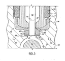
- an injection molding nozzle assembly 10 in accordance with the present invention is located in a cavity plate 34 for the communication of a flowable material to a mold cavity 28 for the formation of a molded article therein.
- Cavity plate 34 is provided with a plurality of cooling passageways 32 therein for the communication of a cooling fluid for the removal of heat from the cavity plate to cool and solidify the flowable material in the mold cavity 28.
- the nozzle assembly 10 is comprised of an elongated nozzle bushing 12 with a nozzle tip 16 affixed to a proximal end of the nozzle bushing.
- the nozzle tip 16 is threaded to the nozzle bushing 12, but any such suitable means could be used.
- a heater 17 is wrapped around the nozzle assembly 10 to maintain the flowable material in a viscous state.
- an optional insulator 14 is located between the nozzle tip 16 and the cooled cavity plate 34 to reduce the transfer of heat from the hot nozzle tip 16 to the cooled cavity plate 34.
- valve member 18 Located co-axially in the nozzle assembly 10 is a movable valve member 18 that extends into a sealing portion 25 adjacent a vestige forming portion 35 of the mold cavity 28.
- the valve member 18 is a slender elongated cylindrical piece that is moved up and down to an open and closed position respectively.
- the valve member 18 When the valve member 18 is in the open position as shown by phantom line 50, the flowable material in melt channel 20 is allowed to enter the mold cavity 28.
- the valve member 18 When placed in the closed position, as shown in FIG. 1, the valve member 18 is in sealing communication with a sealing portion 25 thereby stopping the flow of material to the mold cavity 28.
- an insert 42 with a passageway 41 formed therein is placed in a cavity 44 located in the cavity plate 34 in alignment with the valve member 18.
- the sealing portion 25 is located in this replaceable insert 42 to allow for easy maintenance when leakage around the valve member 18 starts to occur.
- the insert 42 may optionally provide a first chamfer 46 to help guide the valve member 18 when it first enters the passageway 41 and a second chamfer 48 to help guide the valve member further into the sealing portion 25. These chamfers act to reduce wear on both the valve member 18 and the insert 42 and prolong the useable life of both components.
- the vestige 26, as shown in the figures, has a cross-sectional area larger than the face portion 21 of the valve member 18. As such, a portion 23 of the vestige 26 is in thermal communication with the insert 42. Given that the insert 42 is placed in the cooled cavity plate 34, the insert 42 will cool the portion of the molded article vestige 26 in contact with portion 23 faster than the portion in contact with face portion 21 of the hot valve member 18. This differential cooling action will allow the portion of the molded article vestige 26 in contact with portion 23 to solidify before the area adjacent face portion 21. When core 30 is retracted to remove the molded article from the mold cavity 28, this now solidified portion 23 will tend to breakaway more cleanly than the prior art. In addition, due to the location of the sealing portion 25 being internal and displaced from the outer surface of the finished vestige 26, any tearing that may occur when the mold is opened is reduced or eliminated because the tear is not on the surface of the vestige/preform as in the prior art.
- this clean break will result in a more uniform and flat vestige 26 than previously seen.
- a reduced area of crystallinity 40 will form inside the molded article 27 due to the improved cooling of the vestige 26.
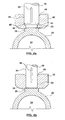
- FIG. 3A an alternative embodiment in accordance with the present invention is shown which is identical to the embodiment in FIG. 3 except for the removal of the insert 42.
- the sealing portion 25 is now located in the cavity plate 34. Cooling of portion 23 will still occur quicker than in the remainder of the vestige 26, which will allow for a substantially clean break when mold core 30 is retracted.
- FIG. 4a and 4b show alternative embodiments of the insert 42 and the valve member 18.
- the valve member 18 has a chamfer 54 near the vestige 26.
- a reduced diameter section of the valve member is in sealing communication with the sealing portion 25 when in the closed position.
- At least one elongated recess 56 is formed in the surface of the valve member 18 which allows the flowable material to be forced up along the valve member 18 as the valve member is brought to the closed position.
- Chamfers 46 and 48 help guide the valve member 18 as it enters the passageway 41 and seats in the sealing portion 25.
- FIG. 4b shows the valve member 18 as one continuous cylinder down to the chamfer at the very bottom.
- the passageway 41 in the insert 42 is also a uniform diameter for most of its length, except for the lead in chamfer 46.
- the sealing portion 25 can be longer and provide a longer lasting seal.
- the recess 56 allows the flowable material to flow up out of passageway 41 as the valve member 18 is brought to a closed position.
Landscapes
- Engineering & Computer Science (AREA)
- Manufacturing & Machinery (AREA)
- Mechanical Engineering (AREA)
- Moulds For Moulding Plastics Or The Like (AREA)
- Injection Moulding Of Plastics Or The Like (AREA)
Claims (7)
- Spritzgießvorrichtung mit:einer Form mit einem Formhohlraum (28), der einen zu formenden Formungsgegenstand definiert, wobei der Formhohlraum (28) einen Formungsteil für ein sichtbares Merkmal aufweist; undeiner Düsenanordnung (10) mit einem Schmelzenkanal zum Zuführen von fließfähigem Material in den Formhohlraum (28), wobei die Düsenanordnung (10) ein bewegliches Ventilelement (18) innerhalb des Schmelzenkanals aufweist, um den Durchfluß des fließfähigen Materials durch die Düse (10) selektiv zu starten und zu stoppen, wobei das Ventilelement einen Stirnteil mit einer ersten Querschnittsfläche hat;einem austauschbaren Einsatz (42), der in der Form nahe und in Anlage am Formhohlraum (28) installiert ist, wobei der austauschbare Einsatz (42) einen Durchgang (41) aufweist, welcher den Schmelzenkanal (20) der Düsenanordnung (10) mit dem Formhohlraum (28) in Verbindung setzt, wobei der Durchgang (41) einen Dichtungsabschnitt (25) nahe dem Formhohlraum (28) aufweist, um einen Endteil des Ventilelementes (18) aufzunehmen, um den Fluß des fließfähigen Materials zu dem Formhohlraum (28) zu stoppen;wobei der das sichtbare Merkmal formende Teil des Hohlraumes, der dem austauschbaren Einsatz (42) benachbart angeordnet ist, die Bildung eines Angußansatzes an dem geformten Gegenstand bewirkt, welcher von diesem absteht, wobei der Angußansatz eine im wesentlichen flache Endfläche hat, und der das sichtbare Merkmal formende Teil bewirkt, daß der Angußansatz sowohl in Kontakt mit dem Stirnteil des Ventilelementes (18) als auch dem austauschbaren Einsatz (42) geformt wird, dadurch gekennzeichnet, daß die flache Endfläche einen Durchmesser hat, der größer als jener des Ventilelementes ist, so daß sich eine Querschnittsfläche des Endes des Angußansatzes ergibt, die größer als die erste Querschnittsfläche des Stirnteiles (21) des Ventilelementes (18) ist.
- Vorrichtung nach Anspruch 1, bei welcher der Querschnitt durch den den Angußansatz bildenden Teil ein Profil hat, von dem zwei parallele Seiten an dem austauschbaren Einsatz (42) auf beiden Seiten des Ventilelementes (18) angreifen.
- Vorrichtung nach Anspruch 1, bei welcher der Durchgang (41) einen ersten Abschnitt und einen zweiten Abschnitt hat, wobei der zweite Abschnitt der Dichtungsabschnitt (25) ist.
- Vorrichtung nach Anspruch 3, bei welcher der erste Abschnitt ein wesentliches Spiel zu dem Ventilelement (18) hat.
- Vorrichtung nach Anspruch 1, bei welcher die Düsenanordnung (10) so konfiguriert ist, daß sie im Betrieb gestattet, daß das fließfähige Material in dem Durchgang (41) entlang des Ventilelementes (18) nach oben gedrückt wird, wenn das Ventilelement (18) in die Schließstellung gebracht wird.
- Vorrichtung nach Anspruch 5, bei welcher das Ventilelement (18) zumindest einen Rücksprung (56) an seiner Außenfläche aufweist.
- Spritzgießvorrichtung mit:einer Form mit einem Formhohlraum (28), der einen zu formenden Formungsgegenstand definiert, wobei der Formhohlraum (28) einen vorstehenden Angußansatz mit einer Dichtungsfläche (25) aufweist; undeiner Düsenanordnung (10) mit einem Schmelzenkanal, um fließfähiges Material dem Formhohlraum (28) zuzuführen, wobei die Düsenanordnung (10) ein bewegbares Ventilelement (18) innerhalb des Schmelzenkanals aufweist, um den Durchfluß des fließfähigen Materials durch die Düse zu starten und zu stoppen, wobei das Ventilelement einen Endabschnitt hat, der so ausgebildet ist, daß er an der Dichtungsfläche des den Angußansatz bildenden Teiles selektiv angreift, um den Durchfluß des fließfähigen Materials zum Formhohlraum (28) zu stoppen, wobei das Ventilelement ferner einen Endflächenabschnitt mit einer ersten Querschnittsfläche aufweist;dadurch gekennzeichnet, daß der den Angußansatz formende Teil des Formhohlraumes bewirkt, daß ein von dem geformten Gegenstand vorstehender Angußansatz gebildet wird, wobei dieser Angußansatz eine im wesentlichen flache Endfläche hat, und der den Angußansatz formende Teil bewirkt, daß der Angußansatz sowohl in Kontakt mit der Endfläche des Ventilelementes (18) als auch dem den Angußansatz formenden Teil geformt wird, dadurch gekennzeichnet, daß die flache Endfläche einen Durchmesser hat, der größer als jener des Ventilelementes ist, so daß sich eine Querschnittsfläche des Endes des Angußansatzes ergibt, die größer als die Oberfläche des Stirnteiles (21) des Ventilelementes (18) ist.
Applications Claiming Priority (3)
| Application Number | Priority Date | Filing Date | Title |
|---|---|---|---|
| US09/900,083 US20030008034A1 (en) | 2001-07-06 | 2001-07-06 | Method and apparatus for injection molding articles |
| US900083 | 2001-07-06 | ||
| PCT/CA2002/000774 WO2003004243A1 (en) | 2001-07-06 | 2002-05-27 | Method and apparatus for injection molding articles |
Publications (2)
| Publication Number | Publication Date |
|---|---|
| EP1406754A1 EP1406754A1 (de) | 2004-04-14 |
| EP1406754B1 true EP1406754B1 (de) | 2007-08-15 |
Family
ID=25411944
Family Applications (1)
| Application Number | Title | Priority Date | Filing Date |
|---|---|---|---|
| EP02729720A Expired - Lifetime EP1406754B1 (de) | 2001-07-06 | 2002-05-27 | Vorrichtung zum spritzgiessen von kunstoffgegenständen |
Country Status (10)
| Country | Link |
|---|---|
| US (2) | US20030008034A1 (de) |
| EP (1) | EP1406754B1 (de) |
| JP (1) | JP2004520984A (de) |
| CN (2) | CN100398295C (de) |
| AT (1) | ATE369964T1 (de) |
| CA (1) | CA2449179A1 (de) |
| DE (1) | DE60221845T2 (de) |
| ES (1) | ES2291468T3 (de) |
| TW (1) | TW590870B (de) |
| WO (1) | WO2003004243A1 (de) |
Families Citing this family (34)
| Publication number | Priority date | Publication date | Assignee | Title |
|---|---|---|---|---|
| US6769901B2 (en) * | 2000-04-12 | 2004-08-03 | Mold-Masters Limited | Injection nozzle system for an injection molding machine |
| US7156651B2 (en) * | 2001-07-06 | 2007-01-02 | Husky Injection Molding Systems Ltd. | Apparatus for injection molding articles |
| CA2358148A1 (en) * | 2001-10-03 | 2003-04-03 | Mold-Masters Limited | A nozzle |
| CA2358187A1 (en) * | 2001-10-03 | 2003-04-03 | Mold-Masters Limited | Nozzle seal |
| US6962492B2 (en) * | 2001-10-05 | 2005-11-08 | Mold-Masters Limited | Gap seal between nozzle components |
| US7128566B2 (en) * | 2002-02-21 | 2006-10-31 | Mold-Masters Limited | Valve pin guiding tip for a nozzle |
| DE10392298B4 (de) | 2002-02-21 | 2016-04-28 | Mold-Masters (2007) Limited | Spritzgießvorrichtung mit einer Ventilnadelführung für eine ventilbetätigte Düse |
| DE10392533B4 (de) * | 2002-04-12 | 2014-07-03 | Mold-Masters (2007) Limited | Spritzgießvorrichtung mit einem Formangussöffnungseinsatz mit Wärmesperre |
| CN100448646C (zh) * | 2002-07-30 | 2009-01-07 | 标准模具(2007)有限公司 | 用于注塑装置中的热流道的阀针导向和对准系统 |
| DE10354456B4 (de) * | 2002-11-21 | 2016-10-13 | Mold-Masters (2007) Limited | Düse mit einer Spitze, einem die Spitze umgebenden Teil und einem Positionierteil und Spritzgießvorrichtung mit der Düse |
| CA2452112A1 (en) * | 2002-12-09 | 2004-06-09 | Mold-Masters Limited | Nozzle tip and seal |
| US7217120B2 (en) * | 2004-06-16 | 2007-05-15 | V-Tek Molding Technologies Inc. | Hot runner nozzle |
| US20070040292A1 (en) * | 2005-08-22 | 2007-02-22 | Fina Technology, Inc. | Polypropylene composition for high gloss retention |
| US7661947B2 (en) * | 2005-11-21 | 2010-02-16 | Epoch Composite Products, Inc. | Method and apparatus for molding roofing products with back gating |
| CN100553924C (zh) * | 2006-01-18 | 2009-10-28 | 鸿富锦精密工业(深圳)有限公司 | 光学元件成型模具 |
| US7458795B2 (en) * | 2006-02-24 | 2008-12-02 | Incoe Corporation | Co-injection nozzle assembly |
| US7589138B2 (en) | 2006-12-05 | 2009-09-15 | Fina Technology, Inc. | Injection molding process |
| US7566216B2 (en) * | 2007-04-29 | 2009-07-28 | Husky Injection Molding Systems Ltd. | Mold assembly using inserts |
| US7568906B2 (en) | 2007-04-30 | 2009-08-04 | Husky Injection Molding Systems Ltd. | Mold assembly using inserts |
| US7513772B2 (en) * | 2007-05-09 | 2009-04-07 | Mold-Masters (2007) Limited | Injection molding nozzle with valve pin alignment |
| US7854876B2 (en) | 2007-05-25 | 2010-12-21 | Ecovision Technologies, Llc | Apparatus and methods for modular preform mold system |
| EP1997603A1 (de) * | 2007-05-31 | 2008-12-03 | Alliance for business solutions A4BS | Modifizierte Heißkanalsysteme zum Spritz-Blasformen |
| US7866974B2 (en) * | 2008-03-18 | 2011-01-11 | Husky Injection Molding Systems Ltd. | Melt distribution apparatus for use in a hot runner |
| CN101590686B (zh) * | 2008-05-26 | 2013-08-14 | 鸿富锦精密工业(深圳)有限公司 | 阀动作的设定方法 |
| US7972132B2 (en) * | 2008-10-10 | 2011-07-05 | Mold-Masters (2007) Ltd | Injection molding valve gated hot runner nozzle |
| EP2555911A4 (de) * | 2010-04-05 | 2014-04-16 | Husky Injection Molding | Formwerkzeuganordnung mit einer in beziehung zu einem stammspitzenteil positionierten harzhaltevorrichtung |
| US8449287B2 (en) | 2010-09-10 | 2013-05-28 | Mold-Masters (2007) Limited | Valve pin for accommodating side loading |
| WO2015105777A1 (en) * | 2014-01-08 | 2015-07-16 | Synventive Molding Solutions, Inc. | Valve pin and nozzle configuration and method of control |
| DE102014210333A1 (de) * | 2014-06-02 | 2015-12-03 | AWETIS Engineering + Manufacturing GmbH | Spritzgussform für Spritzgut |
| DE102014210332A1 (de) * | 2014-06-02 | 2015-12-03 | AWETIS Engineering + Manufacturing GmbH | Einspritzdüse zum Einbringen von Spritzgut in eine Spritzgußform |
| US9248595B2 (en) | 2014-06-24 | 2016-02-02 | Athena Automation Ltd. | Hot runner apparatus for an injection molding machine |
| JP6792397B2 (ja) * | 2016-09-30 | 2020-11-25 | 小林製薬株式会社 | 歯間清掃具の製造方法 |
| CN106994767A (zh) * | 2017-05-05 | 2017-08-01 | 浙江思纳克热流道科技有限公司 | 自带导向定位的阀针结构 |
| IT202100031877A1 (it) * | 2021-12-20 | 2023-06-20 | Inglass S P A Con Socio Unico | “Puntale migliorato per stampaggio a iniezione” |
Citations (2)
| Publication number | Priority date | Publication date | Assignee | Title |
|---|---|---|---|---|
| US6135757A (en) * | 1998-10-16 | 2000-10-24 | Husky Injection Systems Ltd. | Valve gated injection molding system |
| US6220850B1 (en) * | 1999-02-16 | 2001-04-24 | Husky Injection Molding Systems Ltd. | Mold gate insert |
Family Cites Families (14)
| Publication number | Priority date | Publication date | Assignee | Title |
|---|---|---|---|---|
| US4108956A (en) * | 1977-01-21 | 1978-08-22 | Owens-Illinois, Inc. | Injection molding method and apparatus |
| CA1132321A (en) * | 1979-07-20 | 1982-09-28 | Mold-Masters Limited | Injection molding filter assembly |
| CA1136815A (en) * | 1980-07-15 | 1982-12-07 | Jobst U. Gellert | Injection molding nozzle seal |
| CA1261579A (en) * | 1987-03-19 | 1989-09-26 | Mold-Masters Limited | Replaceable rocker arm assembly for injection molding system |
| US5254305A (en) | 1987-12-10 | 1993-10-19 | Otto Hofstetter Ag | Injection nozzle and method for charging an injection nozzle |
| JP3222894B2 (ja) * | 1991-04-10 | 2001-10-29 | 田中貴金属工業株式会社 | 白金族金属回収方法 |
| ATE158749T1 (de) | 1993-08-13 | 1997-10-15 | Awm Werkzeugbau Ag | Spritzdüse |
| CA2175634C (en) * | 1996-05-02 | 2007-08-21 | Klaus Bauer | Injection molding valve member with head and neck portions |
| EP0836925A1 (de) * | 1996-10-09 | 1998-04-22 | EUROTOOL Beheer B.V. | Verschlussdüsenvorrichtung zum Spritzgiessen |
| US6056536A (en) * | 1997-03-20 | 2000-05-02 | Husky Injection Molding Systems Ltd. | Valve gating apparatus for injection molding |
| US6318990B1 (en) * | 1998-10-16 | 2001-11-20 | Mold-Masters Limited | Injection molding nozzle apparatus |
| US6168416B1 (en) | 1998-12-22 | 2001-01-02 | Husky Injection Molding Systems Ltd. | Cooling device for molded articles |
| US6214275B1 (en) * | 1999-06-04 | 2001-04-10 | Husky Injection Molding Systems Ltd. | Injection nozzle and method for injection molding |
| US6220891B1 (en) * | 1999-06-24 | 2001-04-24 | Zetec, Inc. | Probe connector |
-
2001
- 2001-07-06 US US09/900,083 patent/US20030008034A1/en not_active Abandoned
-
2002
- 2002-05-27 EP EP02729720A patent/EP1406754B1/de not_active Expired - Lifetime
- 2002-05-27 CN CNB2005100737502A patent/CN100398295C/zh not_active Expired - Fee Related
- 2002-05-27 JP JP2003510234A patent/JP2004520984A/ja not_active Ceased
- 2002-05-27 CA CA002449179A patent/CA2449179A1/en not_active Abandoned
- 2002-05-27 WO PCT/CA2002/000774 patent/WO2003004243A1/en active IP Right Grant
- 2002-05-27 ES ES02729720T patent/ES2291468T3/es not_active Expired - Lifetime
- 2002-05-27 AT AT02729720T patent/ATE369964T1/de not_active IP Right Cessation
- 2002-05-27 DE DE60221845T patent/DE60221845T2/de not_active Expired - Fee Related
- 2002-05-27 CN CNA028136454A patent/CN1537045A/zh active Pending
- 2002-05-31 TW TW091111704A patent/TW590870B/zh not_active IP Right Cessation
-
2003
- 2003-09-25 US US10/670,870 patent/US7037103B2/en not_active Expired - Fee Related
Patent Citations (2)
| Publication number | Priority date | Publication date | Assignee | Title |
|---|---|---|---|---|
| US6135757A (en) * | 1998-10-16 | 2000-10-24 | Husky Injection Systems Ltd. | Valve gated injection molding system |
| US6220850B1 (en) * | 1999-02-16 | 2001-04-24 | Husky Injection Molding Systems Ltd. | Mold gate insert |
Also Published As
| Publication number | Publication date |
|---|---|
| CN1680085A (zh) | 2005-10-12 |
| TW590870B (en) | 2004-06-11 |
| WO2003004243A1 (en) | 2003-01-16 |
| ATE369964T1 (de) | 2007-09-15 |
| US20040058031A1 (en) | 2004-03-25 |
| US7037103B2 (en) | 2006-05-02 |
| ES2291468T3 (es) | 2008-03-01 |
| JP2004520984A (ja) | 2004-07-15 |
| CA2449179A1 (en) | 2003-01-16 |
| CN100398295C (zh) | 2008-07-02 |
| DE60221845D1 (de) | 2007-09-27 |
| CN1537045A (zh) | 2004-10-13 |
| DE60221845T2 (de) | 2008-05-08 |
| US20030008034A1 (en) | 2003-01-09 |
| EP1406754A1 (de) | 2004-04-14 |
Similar Documents
| Publication | Publication Date | Title |
|---|---|---|
| EP1406754B1 (de) | Vorrichtung zum spritzgiessen von kunstoffgegenständen | |
| WO2005110701A1 (en) | Improved apparatus for injection molding articles | |
| KR100296953B1 (ko) | 플라스틱제품의성형방법및장치 | |
| US6135757A (en) | Valve gated injection molding system | |
| EP0475243B1 (de) | Etagenform mit isoliertem Einspritzkanal | |
| CA2221425C (en) | Side gated injection molding apparatus with actuated manifold | |
| KR100445948B1 (ko) | 인젝션 노즐 및 인젝션 성형 방법 | |
| US5219593A (en) | Injection molding apparatus | |
| US5037598A (en) | Reciprocating heated nozzle | |
| JPH07148786A (ja) | 射出成形用金型装置 | |
| US7458806B2 (en) | Waste-less injection molding fan gate | |
| US5536165A (en) | Injection molding apparatus with nozzle advanceable to mount side gate seals | |
| US20060159798A1 (en) | Method for producing mould parts by injection and plugged needle nozzle for an injection mould | |
| EP0743157B1 (de) | Spritzgiessvorrichtung mit vorschiebbarer Düse zur Montage von seitlichen Anschnittabdichtungen | |
| USRE38480E1 (en) | Injection nozzle and method for injection molding | |
| CA3237443A1 (en) | Injection mold component | |
| JPS5916185Y2 (ja) | 射出成形用金型の改良ゲ−ト | |
| JPH07214605A (ja) | 樹脂成形機 | |
| JPH08127049A (ja) | 樹脂成形機 |
Legal Events
| Date | Code | Title | Description |
|---|---|---|---|
| PUAI | Public reference made under article 153(3) epc to a published international application that has entered the european phase |
Free format text: ORIGINAL CODE: 0009012 |
|
| 17P | Request for examination filed |
Effective date: 20040206 |
|
| AK | Designated contracting states |
Kind code of ref document: A1 Designated state(s): AT BE CH CY DE DK ES FI FR GB GR IE IT LI LU MC NL PT SE TR |
|
| AX | Request for extension of the european patent |
Extension state: AL LT LV MK RO SI |
|
| 17Q | First examination report despatched |
Effective date: 20040512 |
|
| RTI1 | Title (correction) |
Free format text: APPARATUS FOR INJECTION MOLDING ARTICLES |
|
| GRAP | Despatch of communication of intention to grant a patent |
Free format text: ORIGINAL CODE: EPIDOSNIGR1 |
|
| GRAS | Grant fee paid |
Free format text: ORIGINAL CODE: EPIDOSNIGR3 |
|
| GRAA | (expected) grant |
Free format text: ORIGINAL CODE: 0009210 |
|
| AK | Designated contracting states |
Kind code of ref document: B1 Designated state(s): AT BE CH CY DE DK ES FI FR GB GR IE IT LI LU MC NL PT SE TR |
|
| REG | Reference to a national code |
Ref country code: GB Ref legal event code: FG4D |
|
| REG | Reference to a national code |
Ref country code: CH Ref legal event code: EP |
|
| REG | Reference to a national code |
Ref country code: IE Ref legal event code: FG4D |
|
| REF | Corresponds to: |
Ref document number: 60221845 Country of ref document: DE Date of ref document: 20070927 Kind code of ref document: P |
|
| REG | Reference to a national code |
Ref country code: GR Ref legal event code: EP Ref document number: 20070402990 Country of ref document: GR |
|
| REG | Reference to a national code |
Ref country code: SE Ref legal event code: TRGR |
|
| PG25 | Lapsed in a contracting state [announced via postgrant information from national office to epo] |
Ref country code: NL Free format text: LAPSE BECAUSE OF FAILURE TO SUBMIT A TRANSLATION OF THE DESCRIPTION OR TO PAY THE FEE WITHIN THE PRESCRIBED TIME-LIMIT Effective date: 20070815 Ref country code: FI Free format text: LAPSE BECAUSE OF FAILURE TO SUBMIT A TRANSLATION OF THE DESCRIPTION OR TO PAY THE FEE WITHIN THE PRESCRIBED TIME-LIMIT Effective date: 20070815 |
|
| NLV1 | Nl: lapsed or annulled due to failure to fulfill the requirements of art. 29p and 29m of the patents act | ||
| ET | Fr: translation filed | ||
| PG25 | Lapsed in a contracting state [announced via postgrant information from national office to epo] |
Ref country code: AT Free format text: LAPSE BECAUSE OF FAILURE TO SUBMIT A TRANSLATION OF THE DESCRIPTION OR TO PAY THE FEE WITHIN THE PRESCRIBED TIME-LIMIT Effective date: 20070815 Ref country code: CH Free format text: LAPSE BECAUSE OF FAILURE TO SUBMIT A TRANSLATION OF THE DESCRIPTION OR TO PAY THE FEE WITHIN THE PRESCRIBED TIME-LIMIT Effective date: 20070815 Ref country code: LI Free format text: LAPSE BECAUSE OF FAILURE TO SUBMIT A TRANSLATION OF THE DESCRIPTION OR TO PAY THE FEE WITHIN THE PRESCRIBED TIME-LIMIT Effective date: 20070815 |
|
| REG | Reference to a national code |
Ref country code: CH Ref legal event code: PL |
|
| REG | Reference to a national code |
Ref country code: ES Ref legal event code: FG2A Ref document number: 2291468 Country of ref document: ES Kind code of ref document: T3 |
|
| PG25 | Lapsed in a contracting state [announced via postgrant information from national office to epo] |
Ref country code: BE Free format text: LAPSE BECAUSE OF FAILURE TO SUBMIT A TRANSLATION OF THE DESCRIPTION OR TO PAY THE FEE WITHIN THE PRESCRIBED TIME-LIMIT Effective date: 20070815 |
|
| PG25 | Lapsed in a contracting state [announced via postgrant information from national office to epo] |
Ref country code: DK Free format text: LAPSE BECAUSE OF FAILURE TO SUBMIT A TRANSLATION OF THE DESCRIPTION OR TO PAY THE FEE WITHIN THE PRESCRIBED TIME-LIMIT Effective date: 20070815 |
|
| PG25 | Lapsed in a contracting state [announced via postgrant information from national office to epo] |
Ref country code: PT Free format text: LAPSE BECAUSE OF FAILURE TO SUBMIT A TRANSLATION OF THE DESCRIPTION OR TO PAY THE FEE WITHIN THE PRESCRIBED TIME-LIMIT Effective date: 20080115 |
|
| PGFP | Annual fee paid to national office [announced via postgrant information from national office to epo] |
Ref country code: GB Payment date: 20080313 Year of fee payment: 7 Ref country code: LU Payment date: 20080314 Year of fee payment: 7 Ref country code: SE Payment date: 20080313 Year of fee payment: 7 |
|
| PLBE | No opposition filed within time limit |
Free format text: ORIGINAL CODE: 0009261 |
|
| STAA | Information on the status of an ep patent application or granted ep patent |
Free format text: STATUS: NO OPPOSITION FILED WITHIN TIME LIMIT |
|
| 26N | No opposition filed |
Effective date: 20080516 |
|
| PGFP | Annual fee paid to national office [announced via postgrant information from national office to epo] |
Ref country code: DE Payment date: 20080410 Year of fee payment: 7 Ref country code: ES Payment date: 20080312 Year of fee payment: 7 Ref country code: FR Payment date: 20080312 Year of fee payment: 7 |
|
| PGFP | Annual fee paid to national office [announced via postgrant information from national office to epo] |
Ref country code: IT Payment date: 20080514 Year of fee payment: 7 |
|
| PG25 | Lapsed in a contracting state [announced via postgrant information from national office to epo] |
Ref country code: MC Free format text: LAPSE BECAUSE OF NON-PAYMENT OF DUE FEES Effective date: 20080531 |
|
| PGFP | Annual fee paid to national office [announced via postgrant information from national office to epo] |
Ref country code: GR Payment date: 20080312 Year of fee payment: 7 |
|
| PG25 | Lapsed in a contracting state [announced via postgrant information from national office to epo] |
Ref country code: IE Free format text: LAPSE BECAUSE OF NON-PAYMENT OF DUE FEES Effective date: 20080527 |
|
| PG25 | Lapsed in a contracting state [announced via postgrant information from national office to epo] |
Ref country code: CY Free format text: LAPSE BECAUSE OF FAILURE TO SUBMIT A TRANSLATION OF THE DESCRIPTION OR TO PAY THE FEE WITHIN THE PRESCRIBED TIME-LIMIT Effective date: 20070815 |
|
| GBPC | Gb: european patent ceased through non-payment of renewal fee |
Effective date: 20090527 |
|
| REG | Reference to a national code |
Ref country code: FR Ref legal event code: ST Effective date: 20100129 |
|
| PG25 | Lapsed in a contracting state [announced via postgrant information from national office to epo] |
Ref country code: FR Free format text: LAPSE BECAUSE OF NON-PAYMENT OF DUE FEES Effective date: 20090602 |
|
| PG25 | Lapsed in a contracting state [announced via postgrant information from national office to epo] |
Ref country code: GB Free format text: LAPSE BECAUSE OF NON-PAYMENT OF DUE FEES Effective date: 20090527 |
|
| PG25 | Lapsed in a contracting state [announced via postgrant information from national office to epo] |
Ref country code: GR Free format text: LAPSE BECAUSE OF NON-PAYMENT OF DUE FEES Effective date: 20091202 Ref country code: DE Free format text: LAPSE BECAUSE OF NON-PAYMENT OF DUE FEES Effective date: 20091201 |
|
| REG | Reference to a national code |
Ref country code: ES Ref legal event code: FD2A Effective date: 20090528 |
|
| PG25 | Lapsed in a contracting state [announced via postgrant information from national office to epo] |
Ref country code: TR Free format text: LAPSE BECAUSE OF FAILURE TO SUBMIT A TRANSLATION OF THE DESCRIPTION OR TO PAY THE FEE WITHIN THE PRESCRIBED TIME-LIMIT Effective date: 20070815 |
|
| PG25 | Lapsed in a contracting state [announced via postgrant information from national office to epo] |
Ref country code: ES Free format text: LAPSE BECAUSE OF NON-PAYMENT OF DUE FEES Effective date: 20090528 |
|
| PG25 | Lapsed in a contracting state [announced via postgrant information from national office to epo] |
Ref country code: IT Free format text: LAPSE BECAUSE OF NON-PAYMENT OF DUE FEES Effective date: 20090527 |
|
| PG25 | Lapsed in a contracting state [announced via postgrant information from national office to epo] |
Ref country code: LU Free format text: LAPSE BECAUSE OF NON-PAYMENT OF DUE FEES Effective date: 20090527 |
|
| PG25 | Lapsed in a contracting state [announced via postgrant information from national office to epo] |
Ref country code: SE Free format text: LAPSE BECAUSE OF NON-PAYMENT OF DUE FEES Effective date: 20090528 |