EP1406282A2 - Fusible link unit - Google Patents
Fusible link unit Download PDFInfo
- Publication number
- EP1406282A2 EP1406282A2 EP03256200A EP03256200A EP1406282A2 EP 1406282 A2 EP1406282 A2 EP 1406282A2 EP 03256200 A EP03256200 A EP 03256200A EP 03256200 A EP03256200 A EP 03256200A EP 1406282 A2 EP1406282 A2 EP 1406282A2
- Authority
- EP
- European Patent Office
- Prior art keywords
- fuse circuit
- fusible
- link unit
- terminal parts
- linking
- Prior art date
- Legal status (The legal status is an assumption and is not a legal conclusion. Google has not performed a legal analysis and makes no representation as to the accuracy of the status listed.)
- Granted
Links
Images









Classifications
-
- H—ELECTRICITY
- H01—ELECTRIC ELEMENTS
- H01H—ELECTRIC SWITCHES; RELAYS; SELECTORS; EMERGENCY PROTECTIVE DEVICES
- H01H85/00—Protective devices in which the current flows through a part of fusible material and this current is interrupted by displacement of the fusible material when this current becomes excessive
- H01H85/02—Details
- H01H85/04—Fuses, i.e. expendable parts of the protective device, e.g. cartridges
- H01H85/041—Fuses, i.e. expendable parts of the protective device, e.g. cartridges characterised by the type
- H01H85/044—General constructions or structure of low voltage fuses, i.e. below 1000 V, or of fuses where the applicable voltage is not specified
-
- H—ELECTRICITY
- H01—ELECTRIC ELEMENTS
- H01H—ELECTRIC SWITCHES; RELAYS; SELECTORS; EMERGENCY PROTECTIVE DEVICES
- H01H85/00—Protective devices in which the current flows through a part of fusible material and this current is interrupted by displacement of the fusible material when this current becomes excessive
- H01H85/02—Details
- H01H85/47—Means for cooling
-
- H—ELECTRICITY
- H01—ELECTRIC ELEMENTS
- H01H—ELECTRIC SWITCHES; RELAYS; SELECTORS; EMERGENCY PROTECTIVE DEVICES
- H01H85/00—Protective devices in which the current flows through a part of fusible material and this current is interrupted by displacement of the fusible material when this current becomes excessive
- H01H85/02—Details
- H01H85/04—Fuses, i.e. expendable parts of the protective device, e.g. cartridges
- H01H85/05—Component parts thereof
- H01H85/055—Fusible members
- H01H2085/0555—Input terminal connected to a plurality of output terminals, e.g. multielectrode
Definitions
- the present invention relates to a chained type large curernt fusible link unit with fuse circuit structures each containing terminal parts with fusible membersconnected thereto, which are linked in a chain manner through the fusible members.
- JP-A-2000-133114 discloses conventional fusible link unit for example.
- one of fusible link units of this type as shown in Figs. 14 through 16 is known.
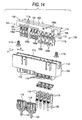
- the fusible link unit designated by reference numeral 100, as shown in Fig. 14, is generally composed of first and second fuse circuit structures 101 and 102 and a housing 103 into which those fuse circuit structures 101 and 102 are assembled.
- the first fuse circuit structure 101 is made up of a linking plate 104, a plurality of terminal parts 106a and 106b, which are coupled through fusible members 105 to the linking plate 104, a battery terminal 107 extended from one end of the linking plate 104, and a common terminal part 108 coupled through a fusible member 105a to the other end of the linking plate 104.
- the first fuse circuit structure 101 is formed by pressing a conductive flat plate member (not shown).
- the second fuse circuit structure 102 is made up of a linking plate 109, a plurality of terminal parts 111a and 111b, which are coupled through fusible members 110 to the linking plate 109, and a common terminal part 112 extended from the other end of the linking plate 109.
- the first fuse circuit structure 101 is formed by pressing a conductive flat plate member (not shown).
- the housing 103 is shaped like a rectangular parallelepiped, and contains a circuit-structure accommodating chamber 114 with an opening 113 open to the upper.
- the housing further includes a plurality of connector housing portions 115 and a plurality of terminal supports 116, which are located under the circuit-structure accommodating chamber 114.
- the first and second fuse circuit structures 101 and 102 are each inserted into the circuit-structure accommodating chamber 114, through the opening 113 of the housing 103.
- an extending direction of the flat surface of each fuse circuit structure is an insertion direction, and the terminal parts (106a, 106b, 111a, 111b) of the fuse circuit structure are first inserted as an insertion tip part.
- the linking plates 104 and 109 of those fuse circuit structures 101 and 102 are located within the circuit-structure accommodating chamber 114.
- the terminal parts 106a, 106b, 111a, and 111b are set at predetermined positions of the connector housing portions 115 and the terminal supports 116.
- first and second fuse circuit structures 101 and 102 are fastened together to the housing 103 by means of a bolt 117.
- the first and second fuse circuit structures 101 and 102 are electrically connected to each other to thereby form a desired fuse circuit.
- the battery terminal 107 is also fastened to the housing 103 by means of a bolt 117b.
- a terminal of a battery cable (not shown) is connected to the battery terminal 107.
- Connected to the terminal parts 106a and 111a in the connector housing portions 115 are the terminals of the counter connectors 118.
- LA terminals 119 are connected to the terminal parts 106b and 111b of the terminal supports 116 by means of screws.
- the connectors of the counter connector 118 and the LA terminals 119 are connected to loads by way of cables 120. Power source is distributed from a battery to those loads, through a fuse circuit. When shortcircuiting occurs in any of the loads and overcurrent flows into the related fusible member 105 (110), the fuse member burns out by heating to thereby prevent trouble by overcurrent.
- the first and second fuse circuit structures 101 and 102 are assembled into the housing 103 to thereby form a unit . Therefore, a fuse circuit containing a number of fusible members (fuses) 105 and 110 may be made considerably compact.
- the first and second fuse circuit structures 101 and 102 may be disposed in a state that those structures are merely spaced a narrow distance W apart from each other. Accordingly, to the fuse circuit extension, what a designer has to do is to slightly increase the housing 103 in the width direction Y, not in the longitudinal direction L.
- the first and second fuse circuit structures 101 and 102 are each formed with one flat plate member. Accordingly, current flows always through the linking plates 104 and 109 even if it is fed from any of the terminal parts 106a, 111a, 106b, and 111b. Accordingly, a problem arises that temperature of the linking plates 104 and 109 rises by the current flowing therethrough.
- an object of the present invention is to provide a fusible link unit which can reliably suppress the temperature rise of the fuse circuit structures with little increasing of the external dimensions of the fuse circuit structures.
- a fusible link unit comprising:
- the terminal parts with the fusible members connected thereto and the terminal parts, which are shared by the part plates, are substantially equal in number.
- two part plates are used.
- the fusible link unit of the embodiment has advantages comparable with those mentioned above.
- Figs. 1 through 14 show the embodiment of the invention.
- Fig. 1 is a perspective view showing a chained type large current fusible link unit.
- Fig. 2 is an exploded, perspective view showing the fusible link unit.
- Fig. 3 is a plan view showing the fusible link unit.
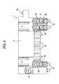
- Fig. 4 is a front view showing the fusible link unit.
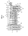
- Fig. 5 is a cross sectional view taken on line A - A in Fig. 3.
- Fig. 6 is a cross sectional view taken on line B - B in Fig. 3.
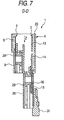
- Fig. 7 is a cross sectional view taken on line D - D in Fig. 3.
- Fig. 8 is a front view showing a first fuse circuit structure of the fusible link unit.
- Figs. 1 is a perspective view showing a chained type large current fusible link unit.
- Fig. 2 is an exploded, perspective view showing the fusible link unit.
- Fig. 3
- FIG. 9(a) and 9(b) are front views showing part plates forming the first fuse circuit structure of the fusible link unit.
- Fig. 10 is a front view showing a second fuse circuit structure of the fusible link unit.
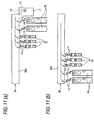
- Figs. 11(a) and 11(b) are front views showing part plates forming the second fuse circuit structure of the fusible link unit.
- Fig. 12 is a cross sectional view taken on line F - F in Fig. 10.
- Fig. 13 is a circuit diagram showing a fuse circuit formedby the first and second fuse circuit structures.
- a fusible link unit 1 is generally made up of a first fuse circuit structure 2 as a bus bar, a second fuse circuit structure 3 also as a bus bar, and a housing 4 which is made of synthetic resin, and into which the first and second fuse circuit structures 2 and 3 are assembled and disposed while being spaced from each other bya predetermined distance.
- the first fuse circuit structure 2 is made up of a narrow, cuboid linking plate 5, a plurality of female terminal parts 7 chain-coupled through fusible members 6 to the linking plate 5 in a short side direction of the linking plate 5, a plurality of screw fixing terminal parts 8 chain-coupled through fusible members 6 to the linking plate 5 in a width side direction of the linking plate 5, a battery terminal (screw fixing terminal part) 9 coupled to the linking plate 5 directly or not through the fusible member in the width direction of the linking plate 5, and an insert lock part 11 coupled to the linking plate 5 through a fusible member 10 in the longitudinal direction of the linking plate 5.
- the first fuse circuit structure 101 is formed by pressing a conductive plane plate (not shown).
- Each fusible member 6 is narrow and shaped like a crank, and a low melting point metal is fastened to a mid part of the crank-shaped fusible member by caulking. When current of a predetermined value or larger flows into the fusible member, the fusible member burns out.
- the fusible member 10 is long, and straight in shape or takes a shape of S or V.
- the fusible members 6 which are located between the linking plate 5 and the screw fixing terminal parts 8 are arranged on a plane, not inclined with respect to the palne direction of the linking plate 5.
- a plurality of female terminal parts 7 are grouped and the female terminal parts of each group are arranged side by side in a chained manner.
- a plurality of screw fixing terminal parts 8 are also grouped and arranged in a similar manner.
- a part of the insert lock part 11 is bent in the vertical direction to form a common terminal part 12.
- the second fuse circuit structure 3 as shown in Fig. 10, is made up of a narrow, rectangular linking plate 13, a plurality of female terminal parts 15 chain-coupled through fusible members 14 to the linking plate 13 in a width direction of the linking plate 13, a plurality of screw fixing terminal parts 16 chain-coupled through fusible members 14 to the linking plate 13 in a width direction of the linking plate 13, and an insert lock part 17 extending in a longitudinal direction of the linking plate 13.
- the second fuse circuit structure 3 is formed by pressing a conductive plane plate (not shown).
- Each fusible member 14, like fusible member 6 of the first fuse circuit structure 2, is narrow and shaped like a crank, and a low melting point metal is fastened to a mid part of the crank-shaped fusible member by caulking. When current of a predetermined value or larger flows into the fusible member, the fusible member burns out. As shown in Figs. 7 and 12, the fusible members 14 which are located between the linking plate 13 and the screw fixing terminal parts 16, like those of the first fuse circuit structure 2, are arranged on a plane, not inclined with respect to the plane direction Z of the linking plate 5,
- a plurality of female terminal parts 15, like those of the first fuse circuit structure 2, are grouped and the female terminal parts of each group are arranged side by side in a chained manner.
- a plurality of screw fixing terminal parts 16 are also grouped and arranged in a similar manner.
- a part of the insert lock part 17 is bent in the vertical direction to form a common terminal part 18, as in the case of the first fuse circuit structure 2.
- the common terminal parts 12 and 18 of the first and second fuse circuit structures 2 and 3, when mounted on the housing 4, are made coherent to each other, together with a bolt 19. Both the common terminal parts 12 and 18 form an alternator terminal.
- the first fuse circuit structure 2 is formed by joining together a first part plate 2a (Fig. 9(a)) and a second part plate 2b (Fig. 9(b).
- the second fuse circuit structure 3 is likewise formed by joining together a first part plate 3a (Fig. 11(a)) and a second part plate 3b (Fig. 11(b).
- the first part plate 2a (3a) is formed with a linking portion 21a (22a) forming the linking plate 5, the fusible members 6, 10 (14), and the terminal parts 7, 8 (15, 16) and the like, which are located in the right area of the linking plate 5.
- the second part plate 2b (3b) is formed with a linking portion 21b (22b) forming the linking plate 13, the fusible members 6, (14), and the terminal parts 7, 8 (15, 16) and the like, which are located in the left area of the linking plate 13.
- the linking plate 5 (13) of the first fuse circuit structure 2 (3) is formed by laminating the two part plates 2a and 2b (3a, 3b).
- the remaining parts are each formed with a single part plate, which is one of those part plates 2a, 3b, 3a and 3b.
- the housing 4 is shaped like a rectangular parallelepiped, and contains a circuit-structure accommodating chamber 26 with an opening 25 open to the upper.
- the housing further includes a plurality of connector housing portions 27 and a plurality of terminal supports 28, which are located under the circuit-structure accommodating chamber 26.
- a transparent cover is attached to the top of the housing 4 to thereby close the opening 25.
- the first and second fuse circuit structures 2 and 3 are each inserted into the circuit-structure accommodating chamber 26, through the opening 25 of the housing 4.
- an extending direction Z of the flat surface of each of the first and second fuse circuit structures 2 and 3 is an insertion direction, and the female terminal parts 7, 15 and the like of the fuse circuit structure are first inserted as an insertion tip part.
- the linking plates 5 and 13 of those fuse circuit structures 2 and 3 are located within the circuit-structure accommodating chamber 26, as shown in Figs. 5 to 8.
- the terminal parts 6, 7, 15 and 16 are set at predetermined positions in the connector housing portions 27 and of the terminal supports 28.
- the common terminal parts 12 and 18 of the first and second fuse circuit structures 2 and 3, together with a bolt 19, are made coherent to one another. Both the common terminal parts 12 and 18 form an alternator terminal.
- the first and second fuse circuit structures 2 and 3 are electrically connected through the common terminal parts 12 and 18, whereby a fuse circuit shown in Fig. 13 is formed.
- the terminal (not shown) for the battery cable is connected to the battery terminal 9, and LA terminals (none of them are shown) for the alternator cable are connected to the alternator terminal 20 by means of the bolt 19 and a nut.
- LA terminals (none of them are shown) for the alternator cable are connected to the alternator terminal 20 by means of the bolt 19 and a nut.
- the LA (circular) terminals 30 are connected to the screw fixing terminal parts 8 and 16 of the terminal supports 28 by means of nut members 29 and screws.
- the male terminals and the LA terminals 30 of the counter connector are connected to related loads by way of a cable 31.
- Power source that is supplied from a battery or an alternator is distributed to the loads by way of the fuse circuit of the fusible link unit 1.
- the alternator supplies electric power source to the battery to thereby charge the battery.
- the female terminal parts 7 (15) with the fusible members 6 (14) connected thereto and the screw fixing terminal parts 8 (16), which are shared by the part plates 2a, 3a, 2b and 3b, are substantially equal in number. Accordingly, current branches into the linking portions 21a, 22a, 21b, 22b of the part plates 2a, 3a, 2b, 3b at almost equal ratios. As a result, the part plates 2a, 3a, 2b and 3b effectively suppress the temperature rise.
- the first and second fuse circuit structures 2 and 3 are each formed by laminating two part plates 2a, 3a, 2b, 3b. If required, three or more part plates may be laminated for the formation of the fuse circuit structure.
- the fuse circuit is constructed with two fuse circuit structures, i.e., the first and second fuse circuit structures 2 and 3. It is readily understood that the invention may be applied to a fusible link unit where the fuse circuit is constructed with a single fuse circuit structure or three or more fuse circuit structures.
- a plurality of part plates include linking portions corresponding to the linking plates and the terminal parts with the fusible members connected thereto, which are shared by the part plates.
- Current flowing through the linking plate of the fuse circuit structure branches into plural current paths to thereby suppress heat generation by the current flow. Accordingly, the fusible link unit can reliably suppress the temperature rise of the fuse circuit structures with little increasing of the external dimensions of the fuse circuit structures.
- Another embodiment of the invention uses two part plates, and hence has advantages comparable with those mentioned above.
Landscapes
- Fuses (AREA)
Abstract
Description
a first part plate includes a first linking portion constituting the linking plate by being laminted by a second linking portion of a second part plate, and
a respective part of the plurality of terminal parts which are connected to the linking plate with a respecitve part of the fusible members are provided with the first part plate.
Claims (3)
- A fusible link unit comprising:wherein the fuse circuit structure is formed by laminating a plurality of part plates,a fuse circuit structure including a plurality of terminal parts linked through fusible members to a linking plate, anda housing into which the fuse circuit structure is assembled,
a first part plate includes a first linking portion constituting the linking plate by being laminted by a second linking portion of a second part plate, and
a respective part of the plurality of terminal parts which are connected to the linking plate with a respecitve part of the fusible members are provided with the first part plate. - A fusible link unit according to claim 1, wherein the first partplate andthe secondpartplate have substantially identical number of the terminal parts to each other.
- A fusible link unit according to claim 1, wherein the number of the part plates is two.
Applications Claiming Priority (2)
| Application Number | Priority Date | Filing Date | Title |
|---|---|---|---|
| JP2002289614A JP2004127698A (en) | 2002-10-02 | 2002-10-02 | Fusible link unit |
| JP2002289614 | 2002-10-02 |
Publications (3)
| Publication Number | Publication Date |
|---|---|
| EP1406282A2 true EP1406282A2 (en) | 2004-04-07 |
| EP1406282A3 EP1406282A3 (en) | 2004-06-02 |
| EP1406282B1 EP1406282B1 (en) | 2008-08-27 |
Family
ID=31987161
Family Applications (1)
| Application Number | Title | Priority Date | Filing Date |
|---|---|---|---|
| EP03256200A Expired - Lifetime EP1406282B1 (en) | 2002-10-02 | 2003-10-01 | Fusible link unit |
Country Status (4)
| Country | Link |
|---|---|
| US (1) | US6824430B2 (en) |
| EP (1) | EP1406282B1 (en) |
| JP (1) | JP2004127698A (en) |
| DE (1) | DE60323194D1 (en) |
Cited By (3)
| Publication number | Priority date | Publication date | Assignee | Title |
|---|---|---|---|---|
| US7663465B2 (en) | 2006-08-04 | 2010-02-16 | Yazaki Corporation | Fusible link unit |
| CN101728138A (en) * | 2008-10-23 | 2010-06-09 | 矢崎总业株式会社 | Blown fuse component |
| CN110459345A (en) * | 2018-05-07 | 2019-11-15 | Aptiv技术有限公司 | bus bar |
Families Citing this family (31)
| Publication number | Priority date | Publication date | Assignee | Title |
|---|---|---|---|---|
| JP2005168178A (en) * | 2003-12-02 | 2005-06-23 | Sumitomo Wiring Syst Ltd | Electrical junction box |
| JP4533827B2 (en) | 2005-09-21 | 2010-09-01 | 矢崎総業株式会社 | Fusible link |
| JP4769621B2 (en) * | 2006-04-18 | 2011-09-07 | 住友電装株式会社 | Bus bar housed in in-vehicle electrical junction box |
| DE102006024391A1 (en) * | 2006-05-24 | 2007-11-29 | Lisa Dräxlmaier GmbH | Motor vehicle safety unit, has bus bar comprising contact guides arranged in order to directly bring contact guides in conducting contact with external potential as plug geometry without interconnection of connecting outline |
| DE102006040824B4 (en) * | 2006-08-31 | 2013-03-28 | Lisa Dräxlmaier GmbH | Power distributor to compensate for a tolerance |
| US20080224814A1 (en) * | 2007-03-13 | 2008-09-18 | Lear Corporation | Electrical assembly and manufacturing method |
| JP4917927B2 (en) | 2007-03-15 | 2012-04-18 | 太平洋精工株式会社 | Multiple fuse unit for vehicles |
| DE102007033263A1 (en) * | 2007-07-17 | 2009-01-29 | Lear Corp., Southfield | Electrical connector for a wiring harness of a vehicle |
| US7663466B1 (en) * | 2007-09-21 | 2010-02-16 | Yazaki North America, Inc. | Corner-mounted battery fuse |
| US7876193B2 (en) * | 2008-04-04 | 2011-01-25 | Lear Corporation | Fuse circuit assembly |
| US8339235B2 (en) * | 2008-08-06 | 2012-12-25 | Beckert James J | Housing securing apparatus for electrical components, especially fuses |
| JP5207533B2 (en) * | 2008-09-05 | 2013-06-12 | 矢崎総業株式会社 | Composite fusible link, fuse box and manufacturing method thereof |
| US20100127817A1 (en) * | 2008-11-25 | 2010-05-27 | Banzo Juan I | Fuse assembly and fuse therefor |
| US8366497B2 (en) * | 2009-06-17 | 2013-02-05 | Lear Corporation | Power terminal |
| JP5486853B2 (en) * | 2009-06-29 | 2014-05-07 | 矢崎総業株式会社 | Fusible link unit |
| JP5346796B2 (en) * | 2009-12-24 | 2013-11-20 | 矢崎総業株式会社 | Fusible link unit |
| JP5603699B2 (en) * | 2010-07-29 | 2014-10-08 | 矢崎総業株式会社 | Fuse unit |
| JP5682067B2 (en) * | 2011-03-31 | 2015-03-11 | 矢崎総業株式会社 | Bus bar for fusible link block circuit configuration, fusible link block, and fusible link block manufacturing method |
| JP5771439B2 (en) * | 2011-04-27 | 2015-08-26 | 矢崎総業株式会社 | Fuse circuit structure |
| US8951051B2 (en) | 2011-10-10 | 2015-02-10 | Lear Corporation | Connector having optimized tip |
| JP5847535B2 (en) * | 2011-10-26 | 2016-01-27 | 矢崎総業株式会社 | Busbar molding die and busbar manufacturing method using this busbar molding die |
| US8808031B2 (en) * | 2011-12-14 | 2014-08-19 | Tyco Electronics Corporation | Battery connector system |
| JP6007012B2 (en) * | 2012-07-23 | 2016-10-12 | 矢崎総業株式会社 | Fuse unit |
| US9166322B2 (en) | 2013-02-08 | 2015-10-20 | Lear Corporation | Female electric terminal with gap between terminal beams |
| US9548553B2 (en) | 2013-03-15 | 2017-01-17 | Lear Corporation | Terminal with front end protection |
| US9190756B2 (en) | 2013-08-01 | 2015-11-17 | Lear Corporation | Electrical terminal assembly |
| US9142902B2 (en) | 2013-08-01 | 2015-09-22 | Lear Corporation | Electrical terminal assembly |
| US9711926B2 (en) | 2013-11-19 | 2017-07-18 | Lear Corporation | Method of forming an interface for an electrical terminal |
| JP6568697B2 (en) * | 2015-03-20 | 2019-08-28 | 株式会社Fuji | Component mounter |
| JP6224042B2 (en) * | 2015-08-31 | 2017-11-01 | 矢崎総業株式会社 | Electrical junction box and wire harness |
| CN113922169B (en) * | 2020-07-09 | 2025-10-17 | 泰科电子(上海)有限公司 | Bus bar assembly |
Family Cites Families (23)
| Publication number | Priority date | Publication date | Assignee | Title |
|---|---|---|---|---|
| US167390A (en) * | 1875-09-07 | Improvement in horse hay-rakes | ||
| US2934627A (en) | 1957-04-09 | 1960-04-26 | Northrop Corp | Electric printed circuit component |
| US4842534A (en) | 1988-10-14 | 1989-06-27 | Interlock Corporation | Fuse/bus bar assembly |
| JPH0716313Y2 (en) | 1989-10-24 | 1995-04-12 | 矢崎総業株式会社 | Electrical connector |
| JP2718606B2 (en) | 1992-09-04 | 1998-02-25 | 矢崎総業株式会社 | Fuse box |
| US5476395A (en) * | 1993-03-01 | 1995-12-19 | Methode Electronics, Inc. | Planar fuse panel |
| JP2587911Y2 (en) | 1993-07-07 | 1998-12-24 | 住友電装株式会社 | Fixing structure of electric connection box and busbar for mini fuse |
| US5643693A (en) | 1995-10-30 | 1997-07-01 | Yazaki Corporation | Battery-mounted power distribution module |
| US6007350A (en) | 1996-09-12 | 1999-12-28 | Sumitomo Wiring Systems, Ltd. | Electrical connection box |
| US5795193A (en) | 1996-10-23 | 1998-08-18 | Yazaki Corporation | Power distribution box with busbar having bolt retaining means |
| JPH10199395A (en) | 1997-01-13 | 1998-07-31 | Taiheiyo Seiko Kk | Multipole type fuse element and multipole type fuse using such element |
| JPH10199396A (en) | 1997-01-13 | 1998-07-31 | Taiheiyo Seiko Kk | Mutipole type fuse element and multipole type fuse using such element |
| GB2326287B (en) * | 1997-06-09 | 2001-10-24 | Delphi Automotive Systems Gmbh | Fuse assembly |
| DE19808237A1 (en) * | 1998-02-06 | 1999-08-19 | Pudenz Wilhelm Gmbh | Fusible conductor structure as a modular system |
| JP2000164111A (en) | 1998-03-16 | 2000-06-16 | Yazaki Corp | High current fuse for automobile |
| JP4091181B2 (en) | 1998-10-27 | 2008-05-28 | 矢崎総業株式会社 | Chained high current fusible link |
| US6178106B1 (en) | 1998-11-03 | 2001-01-23 | Yazaki North America, Inc. | Power distribution center with improved power supply connection |
| TW486848B (en) * | 1999-08-18 | 2002-05-11 | Yazaki Corp | Wire harness circuit configuration method and wire harness |
| US6322376B1 (en) | 2000-03-31 | 2001-11-27 | Yazaki North America | Stud bolt holder for a power distribution box |
| DE60119610T2 (en) * | 2000-04-13 | 2007-04-26 | Sumitomo Wiring Systems, Ltd., Yokkaichi | Electrical connection housing |
| US6402569B1 (en) * | 2000-05-05 | 2002-06-11 | Alcoa Fujikura Ltd. | Molded bus bar system |
| US6558198B2 (en) | 2000-11-30 | 2003-05-06 | Autonetworks Technologies, Ltd. | Fuse device and fuse device connecting structure |
| JP2002329453A (en) | 2001-04-27 | 2002-11-15 | Yazaki Corp | Chain type fuse assembly and layout method thereof |
-
2002
- 2002-10-02 JP JP2002289614A patent/JP2004127698A/en active Pending
-
2003
- 2003-10-01 EP EP03256200A patent/EP1406282B1/en not_active Expired - Lifetime
- 2003-10-01 US US10/674,342 patent/US6824430B2/en not_active Expired - Lifetime
- 2003-10-01 DE DE60323194T patent/DE60323194D1/en not_active Expired - Lifetime
Cited By (5)
| Publication number | Priority date | Publication date | Assignee | Title |
|---|---|---|---|---|
| US7663465B2 (en) | 2006-08-04 | 2010-02-16 | Yazaki Corporation | Fusible link unit |
| DE102007036646B4 (en) * | 2006-08-04 | 2025-06-05 | Yazaki Corporation | Fuse link unit |
| CN101728138A (en) * | 2008-10-23 | 2010-06-09 | 矢崎总业株式会社 | Blown fuse component |
| CN101728138B (en) * | 2008-10-23 | 2014-05-14 | 矢崎总业株式会社 | Blown fuse component |
| CN110459345A (en) * | 2018-05-07 | 2019-11-15 | Aptiv技术有限公司 | bus bar |
Also Published As
| Publication number | Publication date |
|---|---|
| JP2004127698A (en) | 2004-04-22 |
| EP1406282A3 (en) | 2004-06-02 |
| DE60323194D1 (en) | 2008-10-09 |
| EP1406282B1 (en) | 2008-08-27 |
| US6824430B2 (en) | 2004-11-30 |
| US20040130430A1 (en) | 2004-07-08 |
Similar Documents
| Publication | Publication Date | Title |
|---|---|---|
| US6824430B2 (en) | Fusible link unit | |
| US6830482B2 (en) | Fusible link and method of producing said fusible link | |
| US7071808B2 (en) | Fusible link unit | |
| US7420453B2 (en) | Fusible link unit | |
| US4842534A (en) | Fuse/bus bar assembly | |
| EP1145914B1 (en) | Electrical junction box | |
| US7663465B2 (en) | Fusible link unit | |
| KR101461300B1 (en) | Fuse unit | |
| US6887084B2 (en) | Electrical connection box and method for producing it | |
| CA2428612C (en) | Blade fuse | |
| US20050153583A1 (en) | Electric connection box | |
| JP4096431B2 (en) | Multiple fuse element and multiple fuse using the multiple fuse element | |
| US7612647B2 (en) | Fusible link | |
| JP2947079B2 (en) | Connection structure of electrical junction box | |
| JP2004127704A (en) | Fusible link unit | |
| JP4112936B2 (en) | Fusible link unit | |
| JP2004186005A (en) | Fusible link unit | |
| JP2004213906A (en) | Fusible link unit | |
| JP2021013268A (en) | Electric connection box | |
| WO2024127804A1 (en) | Fuse | |
| JP3087634B2 (en) | Electrical junction box | |
| JP2003087935A (en) | Junction box | |
| KR100335193B1 (en) | Prefabricated fuse box | |
| WO2025057854A1 (en) | Bus bar and wiring module | |
| JP2002329458A (en) | Multi-pole type fuse element for vehicle |
Legal Events
| Date | Code | Title | Description |
|---|---|---|---|
| PUAI | Public reference made under article 153(3) epc to a published international application that has entered the european phase |
Free format text: ORIGINAL CODE: 0009012 |
|
| AK | Designated contracting states |
Kind code of ref document: A2 Designated state(s): AT BE BG CH CY CZ DE DK EE ES FI FR GB GR HU IE IT LI LU MC NL PT RO SE SI SK TR |
|
| AX | Request for extension of the european patent |
Extension state: AL LT LV MK |
|
| PUAL | Search report despatched |
Free format text: ORIGINAL CODE: 0009013 |
|
| AK | Designated contracting states |
Kind code of ref document: A3 Designated state(s): AT BE BG CH CY CZ DE DK EE ES FI FR GB GR HU IE IT LI LU MC NL PT RO SE SI SK TR |
|
| AX | Request for extension of the european patent |
Extension state: AL LT LV MK |
|
| 17P | Request for examination filed |
Effective date: 20041122 |
|
| AKX | Designation fees paid |
Designated state(s): DE GB IT |
|
| 17Q | First examination report despatched |
Effective date: 20050222 |
|
| 17Q | First examination report despatched |
Effective date: 20050222 |
|
| RAP1 | Party data changed (applicant data changed or rights of an application transferred) |
Owner name: YAZAKI CORPORATION |
|
| GRAP | Despatch of communication of intention to grant a patent |
Free format text: ORIGINAL CODE: EPIDOSNIGR1 |
|
| GRAS | Grant fee paid |
Free format text: ORIGINAL CODE: EPIDOSNIGR3 |
|
| GRAA | (expected) grant |
Free format text: ORIGINAL CODE: 0009210 |
|
| AK | Designated contracting states |
Kind code of ref document: B1 Designated state(s): DE GB IT |
|
| REG | Reference to a national code |
Ref country code: GB Ref legal event code: FG4D |
|
| REF | Corresponds to: |
Ref document number: 60323194 Country of ref document: DE Date of ref document: 20081009 Kind code of ref document: P |
|
| PLBE | No opposition filed within time limit |
Free format text: ORIGINAL CODE: 0009261 |
|
| STAA | Information on the status of an ep patent application or granted ep patent |
Free format text: STATUS: NO OPPOSITION FILED WITHIN TIME LIMIT |
|
| 26N | No opposition filed |
Effective date: 20090528 |
|
| PGFP | Annual fee paid to national office [announced via postgrant information from national office to epo] |
Ref country code: GB Payment date: 20150930 Year of fee payment: 13 |
|
| PGFP | Annual fee paid to national office [announced via postgrant information from national office to epo] |
Ref country code: DE Payment date: 20150922 Year of fee payment: 13 Ref country code: IT Payment date: 20151026 Year of fee payment: 13 |
|
| REG | Reference to a national code |
Ref country code: DE Ref legal event code: R119 Ref document number: 60323194 Country of ref document: DE |
|
| GBPC | Gb: european patent ceased through non-payment of renewal fee |
Effective date: 20161001 |
|
| PG25 | Lapsed in a contracting state [announced via postgrant information from national office to epo] |
Ref country code: GB Free format text: LAPSE BECAUSE OF NON-PAYMENT OF DUE FEES Effective date: 20161001 Ref country code: DE Free format text: LAPSE BECAUSE OF NON-PAYMENT OF DUE FEES Effective date: 20170503 |
|
| PG25 | Lapsed in a contracting state [announced via postgrant information from national office to epo] |
Ref country code: IT Free format text: LAPSE BECAUSE OF NON-PAYMENT OF DUE FEES Effective date: 20161001 |