EP1405964B1 - Rollable pool cover - Google Patents
Rollable pool cover Download PDFInfo
- Publication number
- EP1405964B1 EP1405964B1 EP03103542A EP03103542A EP1405964B1 EP 1405964 B1 EP1405964 B1 EP 1405964B1 EP 03103542 A EP03103542 A EP 03103542A EP 03103542 A EP03103542 A EP 03103542A EP 1405964 B1 EP1405964 B1 EP 1405964B1
- Authority
- EP
- European Patent Office
- Prior art keywords
- sections
- cover according
- cover
- pole
- flexible sheet
- Prior art date
- Legal status (The legal status is an assumption and is not a legal conclusion. Google has not performed a legal analysis and makes no representation as to the accuracy of the status listed.)
- Expired - Lifetime
Links
- 230000009182 swimming Effects 0.000 claims description 5
- 230000000295 complement effect Effects 0.000 claims description 3
- 239000011324 bead Substances 0.000 claims 1
- 230000003014 reinforcing effect Effects 0.000 abstract description 3
- 239000000463 material Substances 0.000 abstract description 2
- 230000000284 resting effect Effects 0.000 abstract 1
- 230000007246 mechanism Effects 0.000 description 4
- 210000002445 nipple Anatomy 0.000 description 4
- 230000006866 deterioration Effects 0.000 description 3
- 238000005452 bending Methods 0.000 description 2
- 230000000903 blocking effect Effects 0.000 description 2
- 238000004519 manufacturing process Methods 0.000 description 2
- 230000000149 penetrating effect Effects 0.000 description 2
- 238000004804 winding Methods 0.000 description 2
- 238000010276 construction Methods 0.000 description 1
- 238000005520 cutting process Methods 0.000 description 1
- 230000003247 decreasing effect Effects 0.000 description 1
- 238000006073 displacement reaction Methods 0.000 description 1
- 238000009434 installation Methods 0.000 description 1
- 238000000034 method Methods 0.000 description 1
- XLYOFNOQVPJJNP-UHFFFAOYSA-N water Substances O XLYOFNOQVPJJNP-UHFFFAOYSA-N 0.000 description 1
- 238000003466 welding Methods 0.000 description 1
Images


Classifications
-
- F—MECHANICAL ENGINEERING; LIGHTING; HEATING; WEAPONS; BLASTING
- F16—ENGINEERING ELEMENTS AND UNITS; GENERAL MEASURES FOR PRODUCING AND MAINTAINING EFFECTIVE FUNCTIONING OF MACHINES OR INSTALLATIONS; THERMAL INSULATION IN GENERAL
- F16B—DEVICES FOR FASTENING OR SECURING CONSTRUCTIONAL ELEMENTS OR MACHINE PARTS TOGETHER, e.g. NAILS, BOLTS, CIRCLIPS, CLAMPS, CLIPS OR WEDGES; JOINTS OR JOINTING
- F16B7/00—Connections of rods or tubes, e.g. of non-circular section, mutually, including resilient connections
- F16B7/02—Connections of rods or tubes, e.g. of non-circular section, mutually, including resilient connections with conical parts
-
- E—FIXED CONSTRUCTIONS
- E04—BUILDING
- E04H—BUILDINGS OR LIKE STRUCTURES FOR PARTICULAR PURPOSES; SWIMMING OR SPLASH BATHS OR POOLS; MASTS; FENCING; TENTS OR CANOPIES, IN GENERAL
- E04H4/00—Swimming or splash baths or pools
- E04H4/06—Safety devices; Coverings for baths
- E04H4/10—Coverings of flexible material
- E04H4/101—Coverings of flexible material wound-up on a fixed axis
-
- F—MECHANICAL ENGINEERING; LIGHTING; HEATING; WEAPONS; BLASTING
- F16—ENGINEERING ELEMENTS AND UNITS; GENERAL MEASURES FOR PRODUCING AND MAINTAINING EFFECTIVE FUNCTIONING OF MACHINES OR INSTALLATIONS; THERMAL INSULATION IN GENERAL
- F16B—DEVICES FOR FASTENING OR SECURING CONSTRUCTIONAL ELEMENTS OR MACHINE PARTS TOGETHER, e.g. NAILS, BOLTS, CIRCLIPS, CLAMPS, CLIPS OR WEDGES; JOINTS OR JOINTING
- F16B5/00—Joining sheets or plates, e.g. panels, to one another or to strips or bars parallel to them
- F16B5/06—Joining sheets or plates, e.g. panels, to one another or to strips or bars parallel to them by means of clamps or clips
- F16B5/0692—Joining sheets or plates, e.g. panels, to one another or to strips or bars parallel to them by means of clamps or clips joining flexible sheets to other sheets or plates or to strips or bars
-
- F—MECHANICAL ENGINEERING; LIGHTING; HEATING; WEAPONS; BLASTING
- F16—ENGINEERING ELEMENTS AND UNITS; GENERAL MEASURES FOR PRODUCING AND MAINTAINING EFFECTIVE FUNCTIONING OF MACHINES OR INSTALLATIONS; THERMAL INSULATION IN GENERAL
- F16B—DEVICES FOR FASTENING OR SECURING CONSTRUCTIONAL ELEMENTS OR MACHINE PARTS TOGETHER, e.g. NAILS, BOLTS, CIRCLIPS, CLAMPS, CLIPS OR WEDGES; JOINTS OR JOINTING
- F16B7/00—Connections of rods or tubes, e.g. of non-circular section, mutually, including resilient connections
- F16B7/04—Clamping or clipping connections
- F16B7/0406—Clamping or clipping connections for rods or tubes being coaxial
- F16B7/0413—Clamping or clipping connections for rods or tubes being coaxial for tubes using the innerside thereof
- F16B7/042—Clamping or clipping connections for rods or tubes being coaxial for tubes using the innerside thereof with a locking element, e.g. pin, ball or pushbutton, engaging in a hole in the wall of at least one tube
Definitions
- the invention relates to the sector of equipment associated with swimming pools, and more generally to all types of pools. It aims more specifically at roll-up cover, equipped with reinforcing bars to limit the risks of deformation of the cover, especially in the event of a fall in nobody on the indoor pool, and thus limit the risk of accidents.
- the invention aims more particularly at an arrangement of this type of coverage that allows easy transport, regardless of the dimensions of the basin to cover.
- An object of the invention is to prevent the user any assembly operation of the tarpaulin on the tubes, for prevent assembly errors that could lead to the risk of deterioration The tarpaulin.
- the invention therefore relates to a roll-up cover for pools, and especially for swimming pools, which comprises in known manner a flexible tarpaulin, supported by several parallel support bars, the ends of which are intended to rest on the periphery of the basin.
- each support bar is formed of at least two distinct sections, associated with each other from a disassembled configuration, occupying less space than that of the bar of support when it is fit for use.
- the flexible sheet is secured to each end portion of each bar, so as to allow folding at least partially of the flexible sheet on itself when the support bar is in its disassembled configuration.
- the invention consists in equipping the flexible tarpaulin with bars which can be assembled directly on the installation site of the cover, so that during their transport, the bars occupy small dimensions, and significantly lower than those in the basin. In this way, depending on the way whose different sections are arranged in their disassembled state, it is possible to fold the flexible tarpaulin so as to form a set of dimensions much more limited, and therefore easier to transport.
- the sections constituting the bars can be associated with different ways.
- the different sections can be telescopic, and slide one inside the other.
- the number of telescopic sections can be determined according to the width of the pool and the clutter that one wishes to get for transportation. So, each bar may consist of two, three or even four different sections.
- the different sections have indexed profiles, prohibiting the pivoting of sections to inside others. This keeps the alignment between the points on which is hung the flexible cover at the two end sections.
- each bar may comprise locking means of the sliding of the telescopic sections relative to each other.
- These locking means may be made either by clamping rings or by retractable systems cooperating with holes drilled in different sliding tubes. In this way, it is possible to adjust the length of each bar to the precise width of the tarpaulin.
- each bar can then comprise at least one locking element capable of sliding relative to sections, up to the splice area, to prevent the movement of sections one to another.
- the locking element may for example be a sleeve sliding on the outside of the sections, and coming to cover the splicing zone of two tubes, thus maintaining the alignment between the two tubes and conferring also increased resistance to bending.
- Fitting can be facilitated, in the case where the ends facing two adjacent sections have different and complementary shapes.
- the locking element can be made in such a way that slides inside the hollow sections, to come to the level of the zone of junction of two adjacent sections.
- the sections can be articulated relative to each other by hinge elements.
- the set of support bars is formed of sections of similar dimensions, to facilitate the folding of the canvas for transport.
- This construction of support bars in distinct sections therefore applies also to the particular bars located on the edge of the sheet.
- each of the sections of this end bar may have a throat welcoming a rush of solidarity of the edge of the tarpaulin opposite.
- sections are abutted by means of intermediate elements, penetrating partly into each of the sections, and ensuring the continuity of the characteristic groove.
- FIG. 1 illustrates a pool cover (1) according to the invention, which comprises principally a flexible tarpaulin (2) associated with a set of support bars (3) extending transversely and whose ends (4) rest on the periphery (6) of the basin.
- these different support bars (3) pass through the flexible sheet (2) close to their ends, by buttonholes (7) made for this purpose in the cover.
- the ends (4) of the bars rest on the upper face of the sheet (2), above from the periphery (6) of the basin.
- the invention is not limited to this only form of placement of the support bars on the tarpaulin, but covers other variants (not shown) in which the flexible tarpaulin is equipped with sleeves inside which can be set up bars.
- the cover (2) is equipped with two bars end (8,9) disposed at the edges of the flexible sheet.
- One of these end bars (9) is equipped with a mechanism (10) for winding the cover, by means of a crank (11) for example.
- This mechanism being known by elsewhere, and without any immediate relation to the invention, it will not be described further in detail.
- the tarpaulin can also be equipped with different tensioners or other means not shown, ensuring the veneer of the cover on the ground, and avoiding any wind and any intrusion of leaves or other materials under the covers.
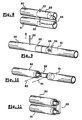
- FIG. 2 illustrates a form of assembly of the sections forming a bar of support. More precisely, it is observed that the support bar (3) comprises two sections, one of which (16) of smaller diameter, slides inside the section (15) of larger diameter. Locking means (17), in the form clamping ring of conventional design, can be set up on the end of the larger diameter tube (15).
- the two tubes (15, 16) may have a singularity of profile, so that the sliding of one relative to the other is done without rotation.
- This singularity can be a slight rib (19,20) or any other analogous means chosen in particular so as not to diminish the resistance of each section at bending. It also helps to maintain the alignment of attachment points (21,22) of the edges of the sheet (3) on the sections (15,16), as shown in Figure 2.
- the attachment of the tarpaulin on the sections can be done by riveting, by welding, or by any other medium, and in particular by an intermediate piece mounted on the end of sections, and secured to the tarpaulin.
- the support bars (3) can be reduced by length, as shown in Figure 3.
- the flexible sheet (2) can then fold in several folds, as shown in Figure 3.
- This folding reduces the width of the cover to a width L corresponding to the length of the bars in their folded configuration.
- the cover can then be wound on itself to occupy a global space particularly reduced.
- FIG. 5 illustrates an alternative embodiment of locking sliding telescopic tubes.
- the two tubes (27,28) are equipped with diametrical holes (29-32), arranged opposite in cases where the two sections are indexed in rotation.
- These holes (29-32) receive an element elastic strap (34), comprising two pins (35) connected to a central portion ensuring an effort, pushing the two nipples diametrically.
- the nipples (35) pass through holes (30,31) drilled in the smaller diameter section (28). When these holes (30,31) are next to holes (29-32) drilled in the section (27) more large diameter, the nipples (35) deviate by penetrating into these holes, thus ensuring the blocking the two sections (27,28) relative to each other.
- the opposite maneuver can be performed by retracting the nipples (35) exerting pressure releasing holes (29-32) made in the section (27) of larger diameter.
- a plurality of holes (29) is pierced in the larger diameter section (27), making it possible to make up for any differences in tolerance between the cutting of bars and that of the tarpaulin.
- the assembly of the different sections constituting the bar can be realized also by butting several tubes (40,41), as illustrated in FIGS. 7.
- the ends (42,43) of the two sections (40,41) of the same diameter are set opposite.
- a sliding sleeve (45) disposed on one of the sections (40) can then be brought to the level of the butting area, to cover it, and prevent any transverse displacement of one section (40,41) relative to the other.
- Locking means such as a clamping ring (46), can provide the holding the locking sleeve (40) in position, as shown in FIG. Fitting can be facilitated when the ends (42,43) of the sections comprise complementary profiles, ensuring self-centering of both sections.
- Number of stitches to be spliced is also determined according to the width of the pool and the size that it is desired to give the cover in the folded position.
- one of the tubes (50) also comprises a sliding piece (52), constituted for example by a tube or a cylinder adapted to slide in its interior.
- this sliding cylinder (52) is held in position at inside the section (50) by means of a pin (53).
- This cylinder of block (52) is connected to a key (55) in the other section (51) by elastic means, constituted by an elastic cable (56) or a spring.
- This spring (56) is under tension when the two sections (50, 51) are separated from each other as shown in Figure 8.
- FIGS. 10 and 11 Another solution for folding the bars is illustrated in FIGS. 10 and 11.
- the ends facing the sections (60, 61) are equipped an intermediate hinge element (62) having two axes of pivoting (63,64).
- This double hinge (62) thus allows the folding of the bar taking into account the diameter of each section (60,61).
- the hinge can preferentially self-locking, thus preventing the unexpected folding of the bar of support. It is also possible to provide a sliding sleeve covering the articulation area.
- the end bar (70) has a longitudinal groove (71) extending over its entire length and having a opening (72) of smaller dimensions.
- This groove (71) receives a ring (73) secured to a selvedge (74) of the flexible sheet (2).
- the invention is not not limited to this single form of throat and rush, but covers all variants allowing the blocking of the edge of the sheet on a bar.
- this end bar is also composed of several distinct sections (70,80), each comprising portion (71,81) of the characteristic groove. These different sections (70,80) are connected by intermediate elements (76), whose profile makes it possible to cash the recess formed by the groove (71,81) of each section. Of course, the in place of these intermediate elements can be done in different ways, and can in particular be locked in position by screwing mechanisms, latching or equivalent.
- the sections (70,80) of the end bar can also adopt other profiles, especially in the case where the end bar must receive a winding mechanism, motorized or manual.
- the pool cover described above has many advantages, including the ability to be collapsed for occupy a small footprint, particularly useful for transport. Transport is therefore easier, and by limiting the risks of deterioration of coverage.
- the assembly of different support bars is particularly easy, and does not require any intervention on the areas of attachment of the tarpaulin on the bars.
Abstract
Description
L'invention se rattache au secteur de l'équipement associé aux piscines, et plus généralement à tous types de bassins. Elle vise plus spécifiquement une couverture enroulable, équipée de barres de renforcement destinées à limiter les risques de déformation de la couverture, notamment en cas de chute d'une personne sur la piscine couverte, et ainsi limiter les risques d'accidents.The invention relates to the sector of equipment associated with swimming pools, and more generally to all types of pools. It aims more specifically at roll-up cover, equipped with reinforcing bars to limit the risks of deformation of the cover, especially in the event of a fall in nobody on the indoor pool, and thus limit the risk of accidents.
L'invention vise plus particulièrement un agencement de ce type de couverture qui en permet le transport aisé, quelles que soient les dimensions du bassin à couvrir.The invention aims more particularly at an arrangement of this type of coverage that allows easy transport, regardless of the dimensions of the basin to cover.
De nombreuses solutions ont déjà été proposées pour renforcer les couvertures de piscines, et éviter qu'une personne ayant chuté sur la couverture, en provoque alors soit sa déchirure, soit son enfoncement dans l'eau du bassin. Toutes ces solutions proposent d'équiper la bâche de la piscine avec des barres de support transversales, dont les extrémités reposent sur la margelle de la piscine, et au-dessus de laquelle repose la bâche.Many solutions have already been proposed to strengthen the swimming pool covers, and to prevent a person falling on the blanket from then causes either its tear or its depression in the water basin. All these solutions propose to equip the cover of the swimming pool with support bars transverse, whose ends rest on the edge of the pool, and above of which the tarpaulin rests.
Un tel dispositif est notamment décrit par exemple dans le document FR 2.613.408 ou dans le document US 5 557 811. De façon générale, ce type de couverture de piscine doit être réalisée avec un très grand soin, pour qu'elle conserve ses propriétés de solidité. En effet, la qualité de l'accrochage des barres de support sur la bâche nécessite l'emploi de matériel spécifique et des contrôles particuliers, qui obligent à réaliser la couverture en usine de fabrication, et non pas directement chez l'utilisateur. Ceci génère toutefois certaines contraintes relatives aux opérations de transport de la bâche du lieu de fabrication vers l'endroit où elle doit être installée. En effet, étant donné que la bâche doit être solidarisée aux barres de support, et que ces dernières sont évidemment plus larges que le bassin à recouvrir, il s'ensuit que la couverture enroulée pour son transport présente un encombrement conséquent. Cet encombrement peut engendrer des frais de transport particulièrement élevés, ainsi que des risques de détérioration de la couverture lors de son transport.Such a device is described for example in document FR 2,613,408 or in US 5,557,811. In general, this type of pool cover must be realized with great care, so that it retains its solidity properties. Indeed, the quality of the hanging of the support bars on the tarpaulin requires the use of specific equipment and particular checks, which oblige to carry out the cover in manufacturing plant, not directly to the user. This however, generates some constraints on the transport operations of the tarpaulin from the place of manufacture to the place where it is to be installed. Indeed, being given that the sheet must be secured to the support bars, and that the latter are obviously wider than the basin to be covered, it follows that the cover wound for its transport has a large size. This congestion can lead to particularly high transport costs, as well as that risks of deterioration of the cover during its transport.
Cet inconvénient empêche même l'emploi de ce type de couverture sur des bassins de grandes largeurs, pour lesquelles le transport devient alors quasiment impossible.This disadvantage prevents even the use of this type of cover on large basins, for which the transport then becomes almost impossible.
Un problème que se propose de résoudre l'invention est celui du coût et des conditions de transport de couvertures de ce type. Un objectif de l'invention est d'éviter à l'utilisateur toute opération d'assemblage de la bâche sur les tubes, pour empêcher des erreurs de montage pouvant générer des risques de détérioration de la bâche.One problem that the invention proposes to solve is that of the cost and cover conditions of this type. An object of the invention is to prevent the user any assembly operation of the tarpaulin on the tubes, for prevent assembly errors that could lead to the risk of deterioration The tarpaulin.
L'invention concerne donc une couverture enroulable pour bassins, et notamment pour piscines, qui comporte de façon connue une bâche flexible, soutenue par plusieurs barres de support parallèles, dont les extrémités sont destinées à reposer sur la périphérie du bassin.The invention therefore relates to a roll-up cover for pools, and especially for swimming pools, which comprises in known manner a flexible tarpaulin, supported by several parallel support bars, the ends of which are intended to rest on the periphery of the basin.
Conformément à l'invention, cette couverture se caractérise en ce que chaque barre de support est formée d'au moins deux tronçons distincts, associés les uns aux autres à partir d'une configuration démontée, occupant un encombrement moindre que celui de la barre de support lorsqu'elle est apte à utilisation. Dans cette couverture, la bâche flexible est solidarisée à chaque tronçon d'extrémité de chaque barre, de manière à permettre le pliage au moins en partie de la bâche flexible sur elle-même lorsque la barre support est dans sa configuration démontée.According to the invention, this cover is characterized in that each support bar is formed of at least two distinct sections, associated with each other from a disassembled configuration, occupying less space than that of the bar of support when it is fit for use. In this cover, the flexible sheet is secured to each end portion of each bar, so as to allow folding at least partially of the flexible sheet on itself when the support bar is in its disassembled configuration.
Autrement dit, l'invention consiste à équiper la bâche flexible de barres qui peuvent être assemblées directement sur le lieu d'installation de la couverture, de sorte que pendant leur transport, les barres occupent des dimensions réduites, et nettement inférieures à celles du bassin. De cette façon, en fonction de la manière dont les différents tronçons sont agencés dans leur état démonté, il est possible de replier la bâche flexible de manière à former un ensemble d'encombrement nettement plus limité, et donc plus facile à transporter.In other words, the invention consists in equipping the flexible tarpaulin with bars which can be assembled directly on the installation site of the cover, so that during their transport, the bars occupy small dimensions, and significantly lower than those in the basin. In this way, depending on the way whose different sections are arranged in their disassembled state, it is possible to fold the flexible tarpaulin so as to form a set of dimensions much more limited, and therefore easier to transport.
L'accrochage de la bâche flexible sur les barres support reste toutefois effectué en usine, avant transport de la couverture vers son lieu d'utilisation, ce qui garantit la qualité de ce montage.The hanging of the flexible tarpaulin on the support bars remains however performed in the factory, before transporting the cover to its place of use, which guarantees the quality of this assembly.
En pratique, les tronçons constituant les barres peuvent être associées de différentes façons. Ainsi, dans une première forme de réalisation, les différents tronçons peuvent être télescopiques, et coulisser les uns à l'intérieur des autres. Le nombre de tronçons télescopiques peut être déterminé en fonction de la largeur de la piscine et de l'encombrement que l'on souhaite obtenir pour le transport. Ainsi, chaque barre peut être constituée de deux, trois, voire quatre tronçons différents.In practice, the sections constituting the bars can be associated with different ways. Thus, in a first embodiment, the different sections can be telescopic, and slide one inside the other. The number of telescopic sections can be determined according to the width of the pool and the clutter that one wishes to get for transportation. So, each bar may consist of two, three or even four different sections.
Avantageusement en pratique, on préfèrera que les différents tronçons présentent des profils indexés, interdisant le pivotement des tronçons les uns à l'intérieur des autres. On conserve de la sorte l'alignement entre les points sur lesquels est accrochée la bâche flexible au niveau des deux tronçons d'extrémité.Advantageously in practice, it will be preferred that the different sections have indexed profiles, prohibiting the pivoting of sections to inside others. This keeps the alignment between the points on which is hung the flexible cover at the two end sections.
En pratique, chaque barre peut comporter des moyens de verrouillage du coulissement des tronçons télescopiques les uns par rapport aux autres. Ces moyens de verrouillage peuvent être réalisés soit par des bagues de serrage, soit par des systèmes rétractables coopérant avec des trous percés dans les différents tubes coulissant. De la sorte, il est possible de régler la longueur de chaque barre à la largeur précise de la bâche.In practice, each bar may comprise locking means of the sliding of the telescopic sections relative to each other. These locking means may be made either by clamping rings or by retractable systems cooperating with holes drilled in different sliding tubes. In this way, it is possible to adjust the length of each bar to the precise width of the tarpaulin.
Dans une autre forme de réalisation, les différents tronçons peuvent être associés en étant raboutés les uns aux autres. Dans ce cas, chaque barre peut comporter alors au moins un élément de blocage apte à coulisser par rapport aux tronçons, jusqu'à la zone de raboutage, pour empêcher le déplacement des tronçons les uns par rapport aux autres. In another embodiment, the different sections can be associated by being patched to each other. In this case, each bar can then comprise at least one locking element capable of sliding relative to sections, up to the splice area, to prevent the movement of sections one to another.
En pratique, l'élément de blocage peut par exemple être un manchon coulissant à l'extérieur des tronçons, et venant recouvrir la zone de raboutage de deux tubes, maintenant ainsi l'alignement entre les deux tubes et conférant également une résistance accrue au cintrage.In practice, the locking element may for example be a sleeve sliding on the outside of the sections, and coming to cover the splicing zone of two tubes, thus maintaining the alignment between the two tubes and conferring also increased resistance to bending.
L'aboutage peut être facilité, dans le cas où les extrémités en regard de deux tronçons adjacents présentent des formes différentes et complémentaires.Fitting can be facilitated, in the case where the ends facing two adjacent sections have different and complementary shapes.
En pratique, l'élément de blocage peut être réalisé de telle sorte qu'il coulisse à l'intérieur des tronçons creux, pour venir au niveau de la zone de jonction de deux tronçons adjacents.In practice, the locking element can be made in such a way that slides inside the hollow sections, to come to the level of the zone of junction of two adjacent sections.
Dans une troisième forme de réalisation, les tronçons peuvent être articulés les uns par rapport aux autres par des éléments formant charnière.In a third embodiment, the sections can be articulated relative to each other by hinge elements.
Bien entendu, l'ensemble des barres de support est formé de tronçons de dimensions analogues, pour faciliter le pliage de la toile en vue de son transport. Cette construction des barres de support en tronçons distincts s'applique donc également aux barres particulières situées sur le bord de la bâche. Dans ce cas, chacun des tronçons de cette barre d'extrémité peut comporter une gorge accueillant un jonc solidaire de la lisière de la bâche en regard. Dans ce cas, les tronçons sont aboutés au moyen d'éléments intermédiaires, pénétrant en partie dans chacun des tronçons, et assurant la continuité de la gorge caractéristique.Of course, the set of support bars is formed of sections of similar dimensions, to facilitate the folding of the canvas for transport. This construction of support bars in distinct sections therefore applies also to the particular bars located on the edge of the sheet. In that case, each of the sections of this end bar may have a throat welcoming a rush of solidarity of the edge of the tarpaulin opposite. In this case, sections are abutted by means of intermediate elements, penetrating partly into each of the sections, and ensuring the continuity of the characteristic groove.
La manière de réaliser l'invention, ainsi que les avantages qui en découlent, ressortiront bien de la description des différents modes de réalisation qui suivent, à l'appui des figures annexées dans lesquelles :
- la figure 1 est une vue en perspective sommaire d'une bâche conforme à l'invention montrée dépliée.
- la figure 2 est une vue en perspective sommaire montrant une barre de support réalisée à partir de tronçons télescopiques.
- la figure 3 est une vue en perspective sommaire de la bâche de la figure 1 montrée pendant l'opération de pliage préalable à son transport.
- la figure 4 est une vue en coupe transversale de deux tronçons télescopiques.
- la figure 5 est une vue en perspective illustrant un moyen particulier de verrouillage du coulissement de deux tronçons télescopiques.
- la figure 6 est une vue en perspective sommaire illustrant l'extrémité de deux tronçons destinés à être raboutés.
- la figure 7 est une vue en perspective sommaire des tronçons de la figure 6 dans une position raboutée.
- la figure 8 est une vue en perspective sommaire d'une variante de réalisation du raboutage de deux tronçons.
- la figure 9 illustre une vue en perspective sommaire des tronçons de la figure 8 montrés en position raboutée.
- la figure 10 est une vue en perspective sommaire d'une variante de réalisation, dans laquelle les tronçons sont articulés par des éléments formant charnière.
- la figure 11 est une vue en perspective des tronçons de la figure 10 dans une position repliée.
- la figure 12 est une vue en perspective sommaire d'une bâche en cours de pliage, équipée de barres réalisées en tronçons raboutés.
- la figure 13 est une vue en coupe transversale d'une barre de support d'extrémité, et de la lisière de la bâche associée.
- la figure 14 est une vue en perspective sommaire illustrant le montage de deux tronçons formant une barre de support d'extrémité.
- Figure 1 is a summary perspective view of a tarp according to the invention shown unfolded.
- Figure 2 is a summary perspective view showing a support bar made from telescopic sections.
- Figure 3 is a brief perspective view of the tarpaulin of Figure 1 shown during the folding operation prior to its transport.
- Figure 4 is a cross-sectional view of two telescopic sections.
- Figure 5 is a perspective view illustrating a particular means of locking the sliding of two telescopic sections.
- Figure 6 is a summary perspective view illustrating the end of two sections to be patched.
- Figure 7 is a rough perspective view of the sections of Figure 6 in a stitched position.
- Figure 8 is a summary perspective view of an alternative embodiment of the splicing of two sections.
- FIG. 9 illustrates a summary perspective view of the sections of FIG. 8 shown in the stitched position.
- Figure 10 is a summary perspective view of an alternative embodiment, wherein the sections are hinged by hinge elements.
- Figure 11 is a perspective view of the sections of Figure 10 in a folded position.
- Figure 12 is a summary perspective view of a tarpaulin being folded, equipped with bars made of stubby sections.
- Figure 13 is a cross-sectional view of an end support bar, and the edge of the associated tarpaulin.
- Figure 14 is a summary perspective view illustrating the mounting of two sections forming an end support bar.
La figure 1 illustre une couverture (1) pour piscine conforme à l'invention, qui comprend de façon principale une bâche flexible (2) associée à un ensemble de barres de support (3) s'étendant transversalement, et dont les extrémités (4) reposent sur la périphérie (6) du bassin. Dans la forme illustrée, ces différentes barres de support (3) traversent la bâche flexible (2) à proximité de leurs extrémités, par des boutonnières (7) réalisées à cet effet dans la bâche. De la sorte, les extrémités (4) des barres reposent sur la face supérieure de la bâche (2), au-dessus de la périphérie (6) du bassin. Toutefois, l'invention n'est pas limitée à cette seule forme de mise en place des barres de support sur la bâche, mais couvre également d'autres variantes (non illustrées) dans lesquelles la bâche flexible est équipée de fourreaux à l'intérieur desquels peuvent être mises en place les barres.FIG. 1 illustrates a pool cover (1) according to the invention, which comprises principally a flexible tarpaulin (2) associated with a set of support bars (3) extending transversely and whose ends (4) rest on the periphery (6) of the basin. In the illustrated form, these different support bars (3) pass through the flexible sheet (2) close to their ends, by buttonholes (7) made for this purpose in the cover. In this way, the ends (4) of the bars rest on the upper face of the sheet (2), above from the periphery (6) of the basin. However, the invention is not limited to this only form of placement of the support bars on the tarpaulin, but covers other variants (not shown) in which the flexible tarpaulin is equipped with sleeves inside which can be set up bars.
Dans la forme illustrée, la couverture (2) est équipée de deux barres d'extrémité (8,9) disposées au niveau des lisières de la bâche flexible. Une de ces barres d'extrémité (9) est équipée d'un mécanisme (10) d'enroulement de la bâche, au moyen d'une manivelle (11) par exemple. Ce mécanisme étant connu par ailleurs, et sans rapport immédiat avec l'invention, il ne sera pas décrit plus en détail.In the illustrated form, the cover (2) is equipped with two bars end (8,9) disposed at the edges of the flexible sheet. One of these end bars (9) is equipped with a mechanism (10) for winding the cover, by means of a crank (11) for example. This mechanism being known by elsewhere, and without any immediate relation to the invention, it will not be described further in detail.
Bien entendu, la bâche peut également être équipée de différents tendeurs ou autres moyens non représentés, assurant le placage de la couverture sur le sol, et évitant ainsi toute prise au vent et toute intrusion de feuilles ou autres matériaux sous la couverture.Of course, the tarpaulin can also be equipped with different tensioners or other means not shown, ensuring the veneer of the cover on the ground, and avoiding any wind and any intrusion of leaves or other materials under the covers.
La figure 2 illustre une forme de montage des tronçons formant une barre de support. Plus précisément, on observe que la barre de support (3) comporte deux tronçons, dont l'un (16) de plus faible diamètre, coulisse à l'intérieur du tronçon (15) de plus fort diamètre. Des moyens de verrouillage (17), sous forme d'une bague de serrage de conception classique, peuvent être mis en place sur l'extrémité du tube de plus gros diamètre (15).FIG. 2 illustrates a form of assembly of the sections forming a bar of support. More precisely, it is observed that the support bar (3) comprises two sections, one of which (16) of smaller diameter, slides inside the section (15) of larger diameter. Locking means (17), in the form clamping ring of conventional design, can be set up on the end of the larger diameter tube (15).
Comme illustré à la figure 4, les deux tubes (15,16) peuvent présenter une singularité de profil, de telle sorte que le coulissement de l'un par rapport à l'autre se fait sans rotation. Cette singularité peut être une légère nervure (19,20) ou tout autre moyen analogue, choisi notamment pour ne pas diminuer la résistance de chaque tronçon au cintrage. Cela permet également de conserver l'alignement des points d'accrochage (21,22) des lisières de la bâche (3) sur les tronçons (15,16), comme illustré à la figure 2. Bien entendu, l'accrochage de la bâche sur les tronçons peut s'effecteur par rivetage, par soudure, ou bien encore par tout autre moyen, et notamment par une pièce intermédiaire montée sur l'extrémité des tronçons, et solidarisée à la bâche.As illustrated in FIG. 4, the two tubes (15, 16) may have a singularity of profile, so that the sliding of one relative to the other is done without rotation. This singularity can be a slight rib (19,20) or any other analogous means chosen in particular so as not to diminish the resistance of each section at bending. It also helps to maintain the alignment of attachment points (21,22) of the edges of the sheet (3) on the sections (15,16), as shown in Figure 2. Of course, the attachment of the tarpaulin on the sections can be done by riveting, by welding, or by any other medium, and in particular by an intermediate piece mounted on the end of sections, and secured to the tarpaulin.
Ainsi, lorsque les bagues de serrage autorisent le coulissement des différents tronçons télescopiques, les barres de support (3) peuvent être réduites de longueur, comme illustré à la figure 3. Dans ce cas, la bâche flexible (2) peut alors être repliée en formant plusieurs plis, comme illustré à la figure 3. Ce pliage permet de réduire la largeur de la couverture à une largeur L correspondant à la longueur des barres dans leur configuration repliée. On atteint ainsi une largeur sensiblement égale à la moitié de la largeur de la couverture dépliée, lorsqu'on emploie deux tronçons télescopiques. Mais cette largeur L peut encore être diminuée par l'emploi d'un nombre supérieur de tronçons télescopiques. Après la première opération de pliage illustrée à la figure 3, la couverture peut ensuite être enroulée sur elle-même pour occuper un encombrement global particulièrement réduit.Thus, when the clamping rings allow the sliding of different telescopic sections, the support bars (3) can be reduced by length, as shown in Figure 3. In this case, the flexible sheet (2) can then fold in several folds, as shown in Figure 3. This folding reduces the width of the cover to a width L corresponding to the length of the bars in their folded configuration. We reach a width substantially equal to half the width of the unfolded blanket, when uses two telescopic sections. But this width L can still be decreased by the use of a greater number of telescopic sections. After the first folding operation illustrated in Figure 3, the cover can then be wound on itself to occupy a global space particularly reduced.
On a illustré à la figure 5 un mode alternatif de réalisation du verrouillage du coulissement des tubes télescopiques. Dans ce cas, les deux tubes (27,28) sont équipés de perçages diamétraux (29-32), disposés en regard dans les cas où les deux tronçons sont indexés en rotation. Ces perçages (29-32) reçoivent un élément élastique (34), comportant deux tétons (35) reliés à une portion centrale assurant un effort, repoussant les deux tétons diamétralement. Les tétons (35) traversent les trous (30,31) percés dans le tronçon de plus faible diamètre (28). Lorsque ces trous (30,31) viennent en regard des trous (29-32) percés dans le tronçon (27) de plus fort diamètre, les tétons (35) s'écartent en pénétrant dans ces trous, assurant ainsi le blocage des deux tronçons (27,28) l'un par rapport à l'autre. La manoeuvre inverse peut être réalisée en escamotant les tétons (35) en exerçant une pression les libérant des trous (29-32) réalisés dans le tronçon (27) de plus grand diamètre. Une pluralité de trous (29) est percée dans le tronçon (27) de plus grand diamètre, permettant de rattraper d'éventuelles différences de tolérance entre la découpe des barres et celle de la bâche.FIG. 5 illustrates an alternative embodiment of locking sliding telescopic tubes. In this case, the two tubes (27,28) are equipped with diametrical holes (29-32), arranged opposite in cases where the two sections are indexed in rotation. These holes (29-32) receive an element elastic strap (34), comprising two pins (35) connected to a central portion ensuring an effort, pushing the two nipples diametrically. The nipples (35) pass through holes (30,31) drilled in the smaller diameter section (28). When these holes (30,31) are next to holes (29-32) drilled in the section (27) more large diameter, the nipples (35) deviate by penetrating into these holes, thus ensuring the blocking the two sections (27,28) relative to each other. The opposite maneuver can be performed by retracting the nipples (35) exerting pressure releasing holes (29-32) made in the section (27) of larger diameter. A plurality of holes (29) is pierced in the larger diameter section (27), making it possible to make up for any differences in tolerance between the cutting of bars and that of the tarpaulin.
Compte tenu du fait que les tronçons télescopiques présentent des diamètres différents, on préfèrera alterner l'orientation des barres sur la couverture, de telle sorte que les tronçons de plus fort diamètre se trouvent distribués de part et d'autre de la bâche, et ne sont pas situés d'un côté uniquement.In view of the fact that the telescopic sections have different diameters, we prefer alternating the orientation of the bars on the cover, so that the sections of larger diameter are distributed on both sides on the other hand, and are not on one side only.
L'assemblage des différents tronçons constituant la barre peut être réalisé également par aboutage de plusieurs tubes (40,41), comme illustré aux figures 6 et 7. Dans ce cas, les extrémités (42,43) des deux tronçons (40,41) de même diamètre sont mis en regard. Un manchon coulissant (45), disposé sur un des tronçons (40), peut alors être amené au niveau de la zone d'aboutage, pour la recouvrir, et empêcher tout déplacement transversal d'un tronçon (40,41) par rapport à l'autre. Des moyens de verrouillage, tel qu'une bague de serrage (46), peuvent assurer le maintien en position du manchon de verrouillage (40), comme illustré à la figure 7. L'aboutage peut être facilité lorsque les extrémités (42,43) des tronçons comportent des profils complémentaires, assurant un auto-centrage des deux tronçons. Bien entendu, des formes différentes de la forme conique illustrée à la figure 6 peuvent être employées, dès lors qu'elle permettent cet auto-centrage. Le nombre de tronçons à rabouter est également déterminé en fonction de la largeur de la piscine et de l'encombrement que l'on souhaite donner à la couverture en position pliée.The assembly of the different sections constituting the bar can be realized also by butting several tubes (40,41), as illustrated in FIGS. 7. In this case, the ends (42,43) of the two sections (40,41) of the same diameter are set opposite. A sliding sleeve (45) disposed on one of the sections (40), can then be brought to the level of the butting area, to cover it, and prevent any transverse displacement of one section (40,41) relative to the other. Locking means, such as a clamping ring (46), can provide the holding the locking sleeve (40) in position, as shown in FIG. Fitting can be facilitated when the ends (42,43) of the sections comprise complementary profiles, ensuring self-centering of both sections. Good Of course, different shapes of the conical shape shown in Figure 6 can to be used, since they allow this self-centering. Number of stitches to be spliced is also determined according to the width of the pool and the size that it is desired to give the cover in the folded position.
Une solution alternative du verrouillage des tubes raboutés, est également illustrée aux figures 8 et 9. Dans ce cas, un des tubes (50) comporte également une pièce coulissante (52), constituée par exemple d'un tube ou d'un cylindre apte à coulisser en son intérieur. Dans la position illustrée à la figure 8, correspondant à une phase de transport, ce cylindre coulissant (52) est maintenu en position à l'intérieur du tronçon (50) par l'intermédiaire d'une goupille (53). Ce cylindre de blocage (52) est relié à une clavette (55) située dans l'autre tronçon (51) par l'intermédiaire de moyens élastiques, constitués par un câble élastique (56) ou un ressort. Ce ressort (56) est sous tension lorsque les deux tronçons (50,51) sont séparés l'un de l'autre, comme illustré à la figure 8.An alternative solution to the locking of the tubes, is also illustrated in FIGS. 8 and 9. In this case, one of the tubes (50) also comprises a sliding piece (52), constituted for example by a tube or a cylinder adapted to slide in its interior. In the position illustrated in Figure 8, corresponding to a transport phase, this sliding cylinder (52) is held in position at inside the section (50) by means of a pin (53). This cylinder of block (52) is connected to a key (55) in the other section (51) by elastic means, constituted by an elastic cable (56) or a spring. This spring (56) is under tension when the two sections (50, 51) are separated from each other as shown in Figure 8.
Lorsque les tronçons (50,51) sont raboutés comme illustré à la figure 9, la goupille (53) est alors extraite, libérant alors le cylindre de blocage (52). Les moyens de rappel (56) attirent alors le cylindre de blocage (52) en direction de la clavette (55), de sorte que le cylindre de blocage (52) vient s'immobiliser au niveau de la zone de jonction des deux tronçons (50,51), assurant ainsi la continuité de la barre. On peut prévoir d'immobiliser le cylindre de blocage lorsque la barre est déployée.When the sections (50, 51) are spliced together as shown in FIG. pin (53) is then extracted, releasing the locking cylinder (52). The return means (56) then attract the locking cylinder (52) towards the key (55), so that the locking cylinder (52) comes to a standstill of the junction zone of the two sections (50,51), thus ensuring the continuity of the closed off. It can be provided to immobilize the locking cylinder when the bar is deployed.
Une autre solution permettant le pliage des barres est illustrée aux figures 10 et 11. Dans ce cas, les extrémités en regard des tronçons (60,61) sont équipés d'un élément (62) intermédiaire formant charnière, comportant deux axes de pivotement (63,64). Cette double charnière (62) permet ainsi le pliage de la barre en tenant compte du diamètre de chaque tronçon (60,61). Lorsque les tronçons (60,61) sont disposés dans la continuité l'un de l'autre, la charnière peut préférentiellement s'autobloquer, empêchant ainsi le repliage inopiné de la barre de support. On peut également prévoir un manchon coulissant venant recouvrir la zone d'articulation.Another solution for folding the bars is illustrated in FIGS. 10 and 11. In this case, the ends facing the sections (60, 61) are equipped an intermediate hinge element (62) having two axes of pivoting (63,64). This double hinge (62) thus allows the folding of the bar taking into account the diameter of each section (60,61). When the sections (60,61) are arranged in continuity with one another, the hinge can preferentially self-locking, thus preventing the unexpected folding of the bar of support. It is also possible to provide a sliding sleeve covering the articulation area.
Les barres formées de tronçons raboutés peuvent ainsi être pliées, comme illustré à la figure 12. Dans ce cas, la bâche flexible (2) se retrouve pliée entre les ensembles de tronçons.The bars formed of joined sections can thus be folded, as illustrated in Figure 12. In this case, the flexible sheet (2) is folded between the sets of sections.
Bien entendu, pour des bâches de plus grandes dimensions, il est possible de rabouter plus de deux tronçons selon les principes illustrés aux figures, sans sortir du cadre de l'invention.Of course, for larger tarpaulins, it is possible to join more than two sections according to the principles illustrated in the figures, without depart from the scope of the invention.
Le principe de décomposition de la barre de support en plusieurs tronçons s'applique également aux barres d'extrémité, notamment dans le cas illustré à la figure 13 où cette barre coopère avec la lisière de la bâche flexible. The principle of decomposing the support bar into several sections also applies to end bars, particularly in the case illustrated in Figure 13 where this bar cooperates with the edge of the flexible sheet.
Ainsi, comme illustré à la figure 13, la barre d'extrémité (70) comporte une gorge longitudinale (71), s'étendant sur toute sa longueur, et présentant une ouverture (72) de plus faibles dimensions. Cette gorge (71) reçoit un jonc (73) solidarisé à une lisière (74) de la bâche flexible (2). Bien entendu, l'invention n'est pas limitée à cette seule forme de gorge et de jonc, mais couvre toutes les variantes permettant le blocage de la lisière de la bâche sur une barre.Thus, as illustrated in FIG. 13, the end bar (70) has a longitudinal groove (71) extending over its entire length and having a opening (72) of smaller dimensions. This groove (71) receives a ring (73) secured to a selvedge (74) of the flexible sheet (2). Of course, the invention is not not limited to this single form of throat and rush, but covers all variants allowing the blocking of the edge of the sheet on a bar.
Conformément à l'invention, cette barre d'extrémité est également constituée de plusieurs tronçons distincts (70,80), comportant donc chacun une portion (71,81) de la gorge caractéristique. Ces différents tronçons (70,80) sont reliés par des éléments intermédiaires (76), dont le profil permet d'encaisser le renfoncement formé par la gorge (71,81) de chaque tronçon. Bien entendu, la mise en place de ces éléments intermédiaires peut s'effectuer de différentes manières, et peut notamment être bloquée en position par des mécanismes de vissage, d'encliquetage ou équivalents. Les tronçons (70,80) de la barre d'extrémité peuvent également adopter d'autres profils, notamment dans le cas où la barre d'extrémité doit recevoir un mécanisme d'enroulage, motorisé ou manuel.According to the invention, this end bar is also composed of several distinct sections (70,80), each comprising portion (71,81) of the characteristic groove. These different sections (70,80) are connected by intermediate elements (76), whose profile makes it possible to cash the recess formed by the groove (71,81) of each section. Of course, the in place of these intermediate elements can be done in different ways, and can in particular be locked in position by screwing mechanisms, latching or equivalent. The sections (70,80) of the end bar can also adopt other profiles, especially in the case where the end bar must receive a winding mechanism, motorized or manual.
Bien entendu, l'invention décrite ci-avant dans son application à des couvertures de piscines, peut se décliner à des applications de recouvrement de tous types de bassins, dans lesquelles la couverture doit présenter une certaine rigidité.Of course, the invention described above in its application to pool covers, can be declined to cover applications of all types of basins, in which the cover must have some degree of rigidity.
Il ressort de ce qui précède que la couverture de piscine décrites ci-avant, présente de multiples avantages, et notamment celui de pouvoir être repliée pour occuper un encombrement réduit, particulièrement utile pour les opérations de transport. Le transport s'effectue donc de manière plus aisée, et en limitant les risques de détérioration de la couverture. En outre, le montage des différentes barres de support est particulièrement aisé, et ne nécessite aucune intervention sur les zones de solidarisation de la bâche sur les barres.It follows from the foregoing that the pool cover described above, has many advantages, including the ability to be collapsed for occupy a small footprint, particularly useful for transport. Transport is therefore easier, and by limiting the risks of deterioration of coverage. In addition, the assembly of different support bars is particularly easy, and does not require any intervention on the areas of attachment of the tarpaulin on the bars.
Claims (11)
- Roller cover (1) for a pool, especially a swimming pool, comprising a flexible sheet (2) supported by several parallel supporting poles (3) whose ends (4) are designed to rest on the pool perimeter (6), and in which each supporting pole (3) is made up of at least two different sections (15, 16) joined together from a retracted configuration and occupying less space than the supporting pole (3) ready for use, which cover is characterized in that the flexible sheet (2) is attached to each end section (15, 16) of each pole (3), so as to allow at least partial folding of the flexible sheet (2) upon itself when the supporting pole (3) is in the retracted configuration.
- Cover according to Claim 1, characterized in that the different sections (15, 16) are telescopic.
- Cover according to Claim 2, characterized in that the different sections (15, 16) have indexed profiles (19, 20) to prevent the sections rotating inside each other.
- Cover according to Claim 2, characterized in that each pole has clamping means (17) for preventing the telescopic sections (15, 16) from sliding relative to each other.
- Cover according to Claim 1, characterized in that the sections (40, 41) are joined end to end.
- Cover according to Claim 5, characterized in that each pole comprises at least one locking part (45) able to slide along the sections (40, 41) to the end-to-end join.
- Cover according to Claim 6, characterized in that the locking part is a sleeve (45) which slides along the outside of the sections.
- Cover according to Claim 5, characterized in that the opposing ends (42, 43) of two adjacent sections (40, 41) are given different and complementary shapes to assist end-to-end joining.
- Cover according to Claim 6, characterized in that the locking part (52) is able to slide along the inside of the hollow sections (50, 51).
- Cover according to Claim 1, characterized in that the sections (60, 61) are hinged to each other by hinge joints (62).
- Cover according to Claim 1, characterized in that the supporting pole or poles situated one edge of the sheet are made up of several sections (70, 80) each comprising a groove (71, 81) which houses a bead (73) attached to the edge (74) of the adjacent flexible sheet (2), the said sections (70, 80) being joined end to end by means of intermediate parts (76) partly fitting into each of the sections (70, 80).
Applications Claiming Priority (2)
| Application Number | Priority Date | Filing Date | Title |
|---|---|---|---|
| FR0212124A FR2845106B1 (en) | 2002-10-01 | 2002-10-01 | Roll up cover for pool |
| FR0212124 | 2002-10-01 |
Publications (2)
| Publication Number | Publication Date |
|---|---|
| EP1405964A1 EP1405964A1 (en) | 2004-04-07 |
| EP1405964B1 true EP1405964B1 (en) | 2005-06-01 |
Family
ID=31985366
Family Applications (1)
| Application Number | Title | Priority Date | Filing Date |
|---|---|---|---|
| EP03103542A Expired - Lifetime EP1405964B1 (en) | 2002-10-01 | 2003-09-24 | Rollable pool cover |
Country Status (4)
| Country | Link |
|---|---|
| EP (1) | EP1405964B1 (en) |
| AT (1) | ATE296933T1 (en) |
| DE (1) | DE60300764T2 (en) |
| FR (1) | FR2845106B1 (en) |
Families Citing this family (2)
| Publication number | Priority date | Publication date | Assignee | Title |
|---|---|---|---|---|
| FR2878274A1 (en) | 2004-11-24 | 2006-05-26 | Marcel Locatelli | REEL, DEROULEUR FOR SWIMMING COVER |
| WO2018150442A1 (en) * | 2017-02-15 | 2018-08-23 | Eurocontainers S.R.L. | Double opening stackable joint |
Family Cites Families (6)
| Publication number | Priority date | Publication date | Assignee | Title |
|---|---|---|---|---|
| US4324370A (en) * | 1980-11-06 | 1982-04-13 | Feherguard Products | Pool cover roller assembly |
| US4744471A (en) * | 1986-03-24 | 1988-05-17 | Leister Judith A | Telescoping rod with locking device |
| CH673501A5 (en) | 1987-04-03 | 1990-03-15 | Glatz Ag | |
| US5557811A (en) * | 1989-08-18 | 1996-09-24 | Hoff; David D. | Free-floating means and method for rolling pool covers |
| FR2690943B1 (en) * | 1992-05-11 | 1994-07-08 | Walter Ets Lucien | ROLL-UP DEVICE FOR COVERING A TANK, ESPECIALLY A POOL POOL. |
| US5810281A (en) * | 1995-11-20 | 1998-09-22 | Kole; John W. | Spool assembly with slotted tubes |
-
2002
- 2002-10-01 FR FR0212124A patent/FR2845106B1/en not_active Expired - Fee Related
-
2003
- 2003-09-24 EP EP03103542A patent/EP1405964B1/en not_active Expired - Lifetime
- 2003-09-24 DE DE60300764T patent/DE60300764T2/en not_active Expired - Lifetime
- 2003-09-24 AT AT03103542T patent/ATE296933T1/en not_active IP Right Cessation
Also Published As
| Publication number | Publication date |
|---|---|
| FR2845106A1 (en) | 2004-04-02 |
| DE60300764D1 (en) | 2005-07-07 |
| ATE296933T1 (en) | 2005-06-15 |
| FR2845106B1 (en) | 2004-12-03 |
| DE60300764T2 (en) | 2005-10-27 |
| EP1405964A1 (en) | 2004-04-07 |
Similar Documents
| Publication | Publication Date | Title |
|---|---|---|
| EP1076138B1 (en) | Windable awning with automatic apron | |
| EP0889180A1 (en) | Connecting device for tent arches | |
| FR2712914A1 (en) | Sun-shade assembly, in particular for the beach | |
| WO2009153454A2 (en) | Hinged folding structure | |
| EP1852289B1 (en) | Device for concealing an automobile, with solidly attachable canvas and corresponding vehicle | |
| EP0534843A1 (en) | Framework for rectangular tent with a double inclined roof | |
| EP4166735A1 (en) | Tent with a deployable cover | |
| EP1405964B1 (en) | Rollable pool cover | |
| EP1566295A1 (en) | Occultation device for motor vehicle, and such a motor vehicle | |
| FR2900598A1 (en) | OCCULTATION DEVICE FOR A MOTOR VEHICLE WITH SOLIDARIZABLE WEBS, AND CORRESPONDING MOTOR VEHICLE. | |
| CA2560871A1 (en) | Rapid folding door | |
| EP3030731B1 (en) | Device forming an outer covering structure of a shelter | |
| FR2765607A1 (en) | Connector for joining frame sections in domed tents with integral frames | |
| FR2673230A1 (en) | FLEXIBLE CURTAIN FOR DOOR RELEVABLE DITE DOOR "ACCORDION". | |
| WO2021023521A1 (en) | Deployable tent provided with arches stressed in bending | |
| FR3037980A1 (en) | MARQUISE COMPRISING SLIDING SLABS | |
| FR2912456A1 (en) | Sectioned cord for radially hooking awning fabric, has flexible locking blade adapted to be carried inside axial groove in close position, when hooking blade is engaged with groove, to lock hooking blade in groove | |
| FR2976011A1 (en) | MODULAR PROTECTION DEVICE | |
| EP0286556A1 (en) | Foldable shelter | |
| EP2146044B1 (en) | Curtain of a screening device, in particular for a roller blind | |
| FR2857688A1 (en) | Folding rising door has guides extending from ends of stiffening bars and engaging with channels offset from surface of pliable panel | |
| FR2774124A1 (en) | ROLLER SHUTTER OR SIMILAR | |
| BE1020840A3 (en) | DEVICE FOR THE AUTOMATIC WINDING OF A COVER CANVAS AND STRUCTURE FOR FORMING COVER EQUIPPED WITH SUCH A DEVICE. | |
| EP0323940A1 (en) | Wind screen | |
| EP1336519B1 (en) | Roller blind for motor vehicle with pull bar comprising a mobile cover |
Legal Events
| Date | Code | Title | Description |
|---|---|---|---|
| PUAI | Public reference made under article 153(3) epc to a published international application that has entered the european phase |
Free format text: ORIGINAL CODE: 0009012 |
|
| AK | Designated contracting states |
Kind code of ref document: A1 Designated state(s): AT BE BG CH CY CZ DE DK EE ES FI FR GB GR HU IE IT LI LU MC NL PT RO SE SI SK TR |
|
| AX | Request for extension of the european patent |
Extension state: AL LT LV MK |
|
| 17P | Request for examination filed |
Effective date: 20040604 |
|
| GRAP | Despatch of communication of intention to grant a patent |
Free format text: ORIGINAL CODE: EPIDOSNIGR1 |
|
| AKX | Designation fees paid |
Designated state(s): AT BE BG CH CY CZ DE DK EE ES FI FR GB GR HU IE IT LI LU MC NL PT RO SE SI SK TR |
|
| GRAS | Grant fee paid |
Free format text: ORIGINAL CODE: EPIDOSNIGR3 |
|
| GRAA | (expected) grant |
Free format text: ORIGINAL CODE: 0009210 |
|
| AK | Designated contracting states |
Kind code of ref document: B1 Designated state(s): AT BE BG CH CY CZ DE DK EE ES FI FR GB GR HU IE IT LI LU MC NL PT RO SE SI SK TR |
|
| PG25 | Lapsed in a contracting state [announced via postgrant information from national office to epo] |
Ref country code: FI Free format text: LAPSE BECAUSE OF FAILURE TO SUBMIT A TRANSLATION OF THE DESCRIPTION OR TO PAY THE FEE WITHIN THE PRESCRIBED TIME-LIMIT Effective date: 20050601 Ref country code: SI Free format text: LAPSE BECAUSE OF FAILURE TO SUBMIT A TRANSLATION OF THE DESCRIPTION OR TO PAY THE FEE WITHIN THE PRESCRIBED TIME-LIMIT Effective date: 20050601 Ref country code: CZ Free format text: LAPSE BECAUSE OF FAILURE TO SUBMIT A TRANSLATION OF THE DESCRIPTION OR TO PAY THE FEE WITHIN THE PRESCRIBED TIME-LIMIT Effective date: 20050601 Ref country code: IT Free format text: LAPSE BECAUSE OF FAILURE TO SUBMIT A TRANSLATION OF THE DESCRIPTION OR TO PAY THE FEE WITHIN THE PRESCRIBED TIME-LIMIT;WARNING: LAPSES OF ITALIAN PATENTS WITH EFFECTIVE DATE BEFORE 2007 MAY HAVE OCCURRED AT ANY TIME BEFORE 2007. THE CORRECT EFFECTIVE DATE MAY BE DIFFERENT FROM THE ONE RECORDED. Effective date: 20050601 Ref country code: SK Free format text: LAPSE BECAUSE OF FAILURE TO SUBMIT A TRANSLATION OF THE DESCRIPTION OR TO PAY THE FEE WITHIN THE PRESCRIBED TIME-LIMIT Effective date: 20050601 Ref country code: AT Free format text: LAPSE BECAUSE OF FAILURE TO SUBMIT A TRANSLATION OF THE DESCRIPTION OR TO PAY THE FEE WITHIN THE PRESCRIBED TIME-LIMIT Effective date: 20050601 Ref country code: TR Free format text: LAPSE BECAUSE OF FAILURE TO SUBMIT A TRANSLATION OF THE DESCRIPTION OR TO PAY THE FEE WITHIN THE PRESCRIBED TIME-LIMIT Effective date: 20050601 Ref country code: GB Free format text: LAPSE BECAUSE OF FAILURE TO SUBMIT A TRANSLATION OF THE DESCRIPTION OR TO PAY THE FEE WITHIN THE PRESCRIBED TIME-LIMIT Effective date: 20050601 Ref country code: IE Free format text: LAPSE BECAUSE OF FAILURE TO SUBMIT A TRANSLATION OF THE DESCRIPTION OR TO PAY THE FEE WITHIN THE PRESCRIBED TIME-LIMIT Effective date: 20050601 Ref country code: NL Free format text: LAPSE BECAUSE OF FAILURE TO SUBMIT A TRANSLATION OF THE DESCRIPTION OR TO PAY THE FEE WITHIN THE PRESCRIBED TIME-LIMIT Effective date: 20050601 Ref country code: EE Free format text: LAPSE BECAUSE OF FAILURE TO SUBMIT A TRANSLATION OF THE DESCRIPTION OR TO PAY THE FEE WITHIN THE PRESCRIBED TIME-LIMIT Effective date: 20050601 Ref country code: RO Free format text: LAPSE BECAUSE OF FAILURE TO SUBMIT A TRANSLATION OF THE DESCRIPTION OR TO PAY THE FEE WITHIN THE PRESCRIBED TIME-LIMIT Effective date: 20050601 |
|
| REG | Reference to a national code |
Ref country code: GB Ref legal event code: FG4D Free format text: NOT ENGLISH |
|
| REG | Reference to a national code |
Ref country code: CH Ref legal event code: EP |
|
| REF | Corresponds to: |
Ref document number: 60300764 Country of ref document: DE Date of ref document: 20050707 Kind code of ref document: P |
|
| REG | Reference to a national code |
Ref country code: IE Ref legal event code: FG4D Free format text: LANGUAGE OF EP DOCUMENT: FRENCH |
|
| PG25 | Lapsed in a contracting state [announced via postgrant information from national office to epo] |
Ref country code: SE Free format text: LAPSE BECAUSE OF FAILURE TO SUBMIT A TRANSLATION OF THE DESCRIPTION OR TO PAY THE FEE WITHIN THE PRESCRIBED TIME-LIMIT Effective date: 20050901 Ref country code: GR Free format text: LAPSE BECAUSE OF FAILURE TO SUBMIT A TRANSLATION OF THE DESCRIPTION OR TO PAY THE FEE WITHIN THE PRESCRIBED TIME-LIMIT Effective date: 20050901 Ref country code: BG Free format text: LAPSE BECAUSE OF FAILURE TO SUBMIT A TRANSLATION OF THE DESCRIPTION OR TO PAY THE FEE WITHIN THE PRESCRIBED TIME-LIMIT Effective date: 20050901 Ref country code: DK Free format text: LAPSE BECAUSE OF FAILURE TO SUBMIT A TRANSLATION OF THE DESCRIPTION OR TO PAY THE FEE WITHIN THE PRESCRIBED TIME-LIMIT Effective date: 20050901 |
|
| PG25 | Lapsed in a contracting state [announced via postgrant information from national office to epo] |
Ref country code: ES Free format text: LAPSE BECAUSE OF FAILURE TO SUBMIT A TRANSLATION OF THE DESCRIPTION OR TO PAY THE FEE WITHIN THE PRESCRIBED TIME-LIMIT Effective date: 20050912 |
|
| PG25 | Lapsed in a contracting state [announced via postgrant information from national office to epo] |
Ref country code: CY Free format text: LAPSE BECAUSE OF FAILURE TO SUBMIT A TRANSLATION OF THE DESCRIPTION OR TO PAY THE FEE WITHIN THE PRESCRIBED TIME-LIMIT Effective date: 20050924 |
|
| PG25 | Lapsed in a contracting state [announced via postgrant information from national office to epo] |
Ref country code: LU Free format text: LAPSE BECAUSE OF NON-PAYMENT OF DUE FEES Effective date: 20050930 Ref country code: MC Free format text: LAPSE BECAUSE OF NON-PAYMENT OF DUE FEES Effective date: 20050930 |
|
| PG25 | Lapsed in a contracting state [announced via postgrant information from national office to epo] |
Ref country code: PT Free format text: LAPSE BECAUSE OF FAILURE TO SUBMIT A TRANSLATION OF THE DESCRIPTION OR TO PAY THE FEE WITHIN THE PRESCRIBED TIME-LIMIT Effective date: 20051103 |
|
| NLV1 | Nl: lapsed or annulled due to failure to fulfill the requirements of art. 29p and 29m of the patents act | ||
| PG25 | Lapsed in a contracting state [announced via postgrant information from national office to epo] |
Ref country code: HU Free format text: LAPSE BECAUSE OF FAILURE TO SUBMIT A TRANSLATION OF THE DESCRIPTION OR TO PAY THE FEE WITHIN THE PRESCRIBED TIME-LIMIT Effective date: 20051202 |
|
| GBV | Gb: ep patent (uk) treated as always having been void in accordance with gb section 77(7)/1977 [no translation filed] |
Effective date: 20050601 |
|
| REG | Reference to a national code |
Ref country code: IE Ref legal event code: FD4D |
|
| PLBE | No opposition filed within time limit |
Free format text: ORIGINAL CODE: 0009261 |
|
| STAA | Information on the status of an ep patent application or granted ep patent |
Free format text: STATUS: NO OPPOSITION FILED WITHIN TIME LIMIT |
|
| 26N | No opposition filed |
Effective date: 20060302 |
|
| REG | Reference to a national code |
Ref country code: FR Ref legal event code: PLFP Year of fee payment: 13 |
|
| PGFP | Annual fee paid to national office [announced via postgrant information from national office to epo] |
Ref country code: CH Payment date: 20150904 Year of fee payment: 13 Ref country code: DE Payment date: 20150914 Year of fee payment: 13 |
|
| REG | Reference to a national code |
Ref country code: FR Ref legal event code: PLFP Year of fee payment: 14 |
|
| REG | Reference to a national code |
Ref country code: DE Ref legal event code: R119 Ref document number: 60300764 Country of ref document: DE |
|
| REG | Reference to a national code |
Ref country code: CH Ref legal event code: PL |
|
| PG25 | Lapsed in a contracting state [announced via postgrant information from national office to epo] |
Ref country code: CH Free format text: LAPSE BECAUSE OF NON-PAYMENT OF DUE FEES Effective date: 20160930 Ref country code: LI Free format text: LAPSE BECAUSE OF NON-PAYMENT OF DUE FEES Effective date: 20160930 Ref country code: DE Free format text: LAPSE BECAUSE OF NON-PAYMENT OF DUE FEES Effective date: 20170401 |
|
| REG | Reference to a national code |
Ref country code: FR Ref legal event code: PLFP Year of fee payment: 15 |
|
| REG | Reference to a national code |
Ref country code: FR Ref legal event code: PLFP Year of fee payment: 16 |
|
| PGFP | Annual fee paid to national office [announced via postgrant information from national office to epo] |
Ref country code: FR Payment date: 20220927 Year of fee payment: 20 Ref country code: BE Payment date: 20220909 Year of fee payment: 20 |
|
| REG | Reference to a national code |
Ref country code: BE Ref legal event code: MK Effective date: 20230924 |