EP1405689A1 - Dispositif de formation d'empreintes en creux sur une surface d'une pièce - Google Patents
Dispositif de formation d'empreintes en creux sur une surface d'une pièce Download PDFInfo
- Publication number
- EP1405689A1 EP1405689A1 EP03292391A EP03292391A EP1405689A1 EP 1405689 A1 EP1405689 A1 EP 1405689A1 EP 03292391 A EP03292391 A EP 03292391A EP 03292391 A EP03292391 A EP 03292391A EP 1405689 A1 EP1405689 A1 EP 1405689A1
- Authority
- EP
- European Patent Office
- Prior art keywords
- crown
- tool
- projecting elements
- cylinder
- moving
- Prior art date
- Legal status (The legal status is an assumption and is not a legal conclusion. Google has not performed a legal analysis and makes no representation as to the accuracy of the status listed.)
- Granted
Links
- 238000007373 indentation Methods 0.000 title claims description 7
- 230000000295 complement effect Effects 0.000 claims abstract description 4
- 238000002485 combustion reaction Methods 0.000 claims description 6
- PZNSFCLAULLKQX-UHFFFAOYSA-N Boron nitride Chemical compound N#B PZNSFCLAULLKQX-UHFFFAOYSA-N 0.000 claims description 4
- 229910052582 BN Inorganic materials 0.000 claims description 3
- 229910000997 High-speed steel Inorganic materials 0.000 claims description 3
- 238000005219 brazing Methods 0.000 claims description 3
- 239000000919 ceramic Substances 0.000 claims description 3
- 229910003460 diamond Inorganic materials 0.000 claims description 3
- 239000010432 diamond Substances 0.000 claims description 3
- UONOETXJSWQNOL-UHFFFAOYSA-N tungsten carbide Chemical compound [W+]#[C-] UONOETXJSWQNOL-UHFFFAOYSA-N 0.000 claims description 3
- 238000003466 welding Methods 0.000 claims description 3
- 239000000463 material Substances 0.000 description 7
- 208000031968 Cadaver Diseases 0.000 description 4
- 238000006073 displacement reaction Methods 0.000 description 4
- 238000010586 diagram Methods 0.000 description 3
- 238000004519 manufacturing process Methods 0.000 description 2
- 230000000284 resting effect Effects 0.000 description 2
- 238000012550 audit Methods 0.000 description 1
- 238000005452 bending Methods 0.000 description 1
- 230000015572 biosynthetic process Effects 0.000 description 1
- 238000000576 coating method Methods 0.000 description 1
- 230000007547 defect Effects 0.000 description 1
- 230000002542 deteriorative effect Effects 0.000 description 1
- 238000009826 distribution Methods 0.000 description 1
- 238000003754 machining Methods 0.000 description 1
- 238000000034 method Methods 0.000 description 1
- 238000003825 pressing Methods 0.000 description 1
- OANVFVBYPNXRLD-UHFFFAOYSA-M propyromazine bromide Chemical compound [Br-].C12=CC=CC=C2SC2=CC=CC=C2N1C(=O)C(C)[N+]1(C)CCCC1 OANVFVBYPNXRLD-UHFFFAOYSA-M 0.000 description 1
Images


Classifications
-
- B—PERFORMING OPERATIONS; TRANSPORTING
- B21—MECHANICAL METAL-WORKING WITHOUT ESSENTIALLY REMOVING MATERIAL; PUNCHING METAL
- B21H—MAKING PARTICULAR METAL OBJECTS BY ROLLING, e.g. SCREWS, WHEELS, RINGS, BARRELS, BALLS
- B21H7/00—Making articles not provided for in the preceding groups, e.g. agricultural tools, dinner forks, knives, spoons
- B21H7/18—Making articles not provided for in the preceding groups, e.g. agricultural tools, dinner forks, knives, spoons grooved pins; Rolling grooves, e.g. oil grooves, in articles
-
- B—PERFORMING OPERATIONS; TRANSPORTING
- B23—MACHINE TOOLS; METAL-WORKING NOT OTHERWISE PROVIDED FOR
- B23P—METAL-WORKING NOT OTHERWISE PROVIDED FOR; COMBINED OPERATIONS; UNIVERSAL MACHINE TOOLS
- B23P9/00—Treating or finishing surfaces mechanically, with or without calibrating, primarily to resist wear or impact, e.g. smoothing or roughening turbine blades or bearings; Features of such surfaces not otherwise provided for, their treatment being unspecified
- B23P9/02—Treating or finishing by applying pressure, e.g. knurling
-
- F—MECHANICAL ENGINEERING; LIGHTING; HEATING; WEAPONS; BLASTING
- F02—COMBUSTION ENGINES; HOT-GAS OR COMBUSTION-PRODUCT ENGINE PLANTS
- F02F—CYLINDERS, PISTONS OR CASINGS, FOR COMBUSTION ENGINES; ARRANGEMENTS OF SEALINGS IN COMBUSTION ENGINES
- F02F1/00—Cylinders; Cylinder heads
- F02F1/02—Cylinders; Cylinder heads having cooling means
- F02F1/10—Cylinders; Cylinder heads having cooling means for liquid cooling
- F02F1/16—Cylinder liners of wet type
-
- F—MECHANICAL ENGINEERING; LIGHTING; HEATING; WEAPONS; BLASTING
- F02—COMBUSTION ENGINES; HOT-GAS OR COMBUSTION-PRODUCT ENGINE PLANTS
- F02F—CYLINDERS, PISTONS OR CASINGS, FOR COMBUSTION ENGINES; ARRANGEMENTS OF SEALINGS IN COMBUSTION ENGINES
- F02F1/00—Cylinders; Cylinder heads
- F02F1/18—Other cylinders
- F02F1/20—Other cylinders characterised by constructional features providing for lubrication
Definitions
- the present invention relates to a training device shallow intaglio prints on a part surface, such as for example a bore of a liner of a cylinder of a combustion engine.
- a line of research in this area consists of reducing, by on the one hand, consumption in the city and, on the other hand, the mechanical losses which are due to friction of the pistons on the wall of the cylinder bores.
- the hollow imprints thus formed are of dimensions, of shapes precise and evenly distributed over the surface.
- the object of the invention is to avoid these drawbacks by proposing a easy-to-install shallow intaglio device at low cost and in efficient cycle times and compatible with mass production of motors.
- Fig. 1 there is shown schematically a device for training designated as a whole by the reference 10 and which is intended for form shallow indentations 2 on a surface 3 of a room 1.
- surface 3 consists of an internal surface of a cylinder, such as for example a bore of a liner of a combustion engine cylinder.
- the training device 10 is intended to forming shallow indentations on all types of pieces of any shape, such as cylindrical or planar and made in various materials.
- the device 10 includes a tool 11 formed by a body 12 supporting, on the one hand, a reference cylinder 13 and, on the other hand, a ring 14 coaxial with said cylinder.
- the reference cylinder 13 is intended to be applied to the surface 3 of the part 1, as shown in FIG. 1, and the crown 14 is provided on its outer face with a series of projecting elements 15 comprising each an active surface 15a of shape complementary to the imprints 2 to realize on said surface 3.
- the body 12 also includes a connecting member 16 with means for moving the tool 11 along the surface 3, means drive in rotation of this tool and vertical displacement means said tool.
- the means for moving the tool 11 and rotational drive of this tool 11 are constituted by a pin 30 of a machine tool and which engages on the connecting member 16.
- the crown 14 is either integral with the body 12 of the tool 11 and in this case this ring 14 is rotated with the body 12 by through the spindle 30, independent of this body 12 and freely mounted rotating on the latter.
- a bearing not shown, is fixed between the body 12 and the crown 14 so that it is rotated by the friction between the projecting elements 15 and the surface 3.
- the protruding elements 15 form a single piece with the crown 14.
- the outer face of the crown 14 is machined so that the active parts 15a projecting elements 15 form a relief opposite to that of the imprints 2 to be obtained on the surface 3 of the part 1.
- the hardness of the material of the crown 14 is sufficient to print the imprints 2 on the surface 3 without deteriorating.
- the projecting elements 15 are formed by removable plates 17 and independent of the crown 14 and which each have an active part 15a of relief opposite to that of the imprints 2 to be obtained on the surface 3.
- Each plate 17 is arranged in a housing 18 formed in the crown 14 and each housing 18 is provided with an adjustment system, not shown, allowing the plate 17 to be moved radially corresponding so as to compensate for the wear of the active part 15a.
- the adjustment system is constituted for example by a system screw type classic.
- the projecting elements 15 are fixed to the crown 14 for example by welding or by brazing and this ring 14 is radially expandable using a appropriate mechanism.
- the crown 14 is made of a material allowing its radial expansion and it has recesses 14a.
- the radial expansion mechanism of the crown 14 comprises a cone 19 concentric with said crown 14 and which is vertically movable by a screw / nut system designated by the general reference 20.
- the rotation of the screw / nut mechanism 20 makes it possible to move vertically the cone 19 and thereby obtain an expansion of the crown 14 necessary for the radial adjustment of the projecting elements 15 to control the depth of the imprints 2 made on the surface 3. Indeed, wear of the active part 15a of the projecting elements 15 requires sharpening. The result therefore a removal of material which must be compensated by an increase in the original diameter of the crown 14.
- this assembly is made for example in high-speed steel or tungsten carbide or ceramic boron nitride or diamond.
- the projecting elements 15 are independent of the crown 14, they are made from one of these materials. These materials can also be coated by a coating process under vacuum for example by a harder material and / or having a coefficient of different friction.
- Reference cylinder 13 is precision machined and has two functions. The first function is that it acts as a reference for adjusting the crown 14 in diameter. Indeed, the external relief of the crown 14 is machined in the case of a single piece or radially adjusted relative to this cylinder 13 in the case of projecting elements 15 independent of crown 14.
- the second function resides in the fact that this cylinder 13 makes reference office for the path of the tool 11 on the surface 3 of the part 2. Indeed, although this surface 3 is not geometrically perfect and the displacement of the spindle 30 of the machine tool is not either, the depth of imprints 2 to be produced must be precise, of the order of a few microns. Thus, during the various combined movements of the tool 11, the cylinder 13 is still resting on the surface 3. The geometric defects of this surface 3 and / or control faults of the machine tool carrying the spindle 30 are absorbed by the bending of the assembly constituted by the tool 11 and the Machine tool.
- tool 11 turns on itself according to the arrow "a” and its axis which is parallel to the surface 3, described also a circle according to arrow "b".
- the combination of these two displacements "a” and “b” which result from the combination of two movements of the spindle 30 of the machine tool makes it possible to make the impressions 2 by pressing the parts active 15a of the projecting elements 15 of the crown 14.
- the association of movements "a” and “b” ensure a zero linear speed at the point of contact between the tool 11 and the surface 3 of the part 1.
- the tool 11 is also movable according to a third movement indicated by the arrow "c" in Fig. 1 which is parallel to the plane of the surface 3 in the case of a flat surface or which is parallel to the axis of the cylinder in the case of a cylindrical surface 3.
- the projecting elements 15 are distributed so uniform on the external face of the crown 14.
- the device according to the invention has the advantage of being of a simple implementation and therefore reduce costs, by obtaining high-performance cycles compatible with mass production of parts.
Landscapes
- Engineering & Computer Science (AREA)
- Mechanical Engineering (AREA)
- General Engineering & Computer Science (AREA)
- Chemical & Material Sciences (AREA)
- Combustion & Propulsion (AREA)
- Agronomy & Crop Science (AREA)
- Life Sciences & Earth Sciences (AREA)
- Cylinder Crankcases Of Internal Combustion Engines (AREA)
- Shaping Of Tube Ends By Bending Or Straightening (AREA)
- Absorbent Articles And Supports Therefor (AREA)
- Professional, Industrial, Or Sporting Protective Garments (AREA)
- Blow-Moulding Or Thermoforming Of Plastics Or The Like (AREA)
- Earth Drilling (AREA)
- Machines For Manufacturing Corrugated Board In Mechanical Paper-Making Processes (AREA)
- Extrusion Moulding Of Plastics Or The Like (AREA)
Abstract
Description
- un cylindre de référence destiné à être appliqué sur la surface,
- une couronne coaxiale audit cylindre et munie, sur sa face externe, d'une série d'éléments en saillie comprenant chacun une partie active de forme complémentaire aux empreintes en creux, et
- un organe de liaison avec des moyens de déplacement de l'outil le long de la surface, des moyens d'entraínement en rotation de cet outil et des moyens de déplacement vertical dudit outil.
- la couronne est solidaire du corps de l'outil,
- la couronne est indépendante du corps et est montée libre en rotation sur ledit corps,
- les éléments en saillie forment avec la couronne une pièce monobloc,
- les éléments en saillie sont formés par des plaquettes amovibles et indépendantes de la couronne et disposées chacune dans un logement ménagé dans ladite couronne,
- chaque plaquette est déplaçable radialement dans le logement correspondant au moyen d'un système de réglage,
- les éléments en saillie sont fixés sur la face externe de la couronne par exemple par soudage ou par brasage,
- la couronne est expansible radialement à l'aide d'un mécanisme comportant un cône concentrique à ladite couronne et déplaçable verticalement par un système vis/écrou,
- les éléments en saillie sont uniformément répartis à la périphérie de la couronne,
- la couronne et/ou les éléments en saillie sont réalisés en acier rapide ou en carbure de tungstène ou en céramique ou en nitrure de bore ou en diamant,
- les moyens de déplacement et d'entraínement en rotation de l'outil comprennent une broche d'une machine outil reliée à l'organe de liaison du corps de cet outil,
- la surface de la pièce est formée par un alésage d'une chemise d'un cylindre d'un moteur à combustion,
- les empreintes en creux formées par la partie active des éléments en saillie ont une profondeur comprise entre 10 et 15 microns ± 10%.
- la Fig. 1 est une vue schématique en perspective d'un outil d'un dispositif conforme à l'invention,
- la Fig. 2 est une vue schématique en perspective et à plus grande échelle de plusieurs éléments en saillie de l'outil de la Fig. 1,
- la Fig. 3 est une vue schématique en perspective d'une première variante de l'outil du dispositif,
- la Fig. 4 est une vue schématique en perspective d'une seconde variante de l'outil du dispositif,
- la Fig. 5 est un schéma montrant les déplacements de l'outil du dispositif,
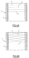
- les Figs. 6A et 6B sont des schémas de deux exemples de répartition des empreintes en creux sur une surface et réalisées par le dispositif de formation selon l'invention.
Claims (13)
- Dispositif de formation d'empreintes en creux (2) de faible profondeur sur une surface (3) d'une pièce (1), caractérisé en ce qu'il comprend un outil (11) cylindrique formé par un corps (12) comportant :un cylindre (13) de référence destiné à être appliqué sur la surface (3),une couronne (14) coaxiale audit cylindre (13) et munie, sur sa face externe, d'une série d'éléments en saillie (15) comprenant chacune une partie active (15a) de forme complémentaire aux empreintes en creux (2), etun organe de liaison (16) avec des moyens de déplacement de l'outil (11) le long de la surface (3), des moyens d'entraínement en rotation de cet outil (11 ) et des moyens de déplacement vertical dudit outil (11 ).
- Dispositif selon la revendication 1, caractérisé en ce que la couronne (14) est solidaire du corps (12) de l'outil (11).
- Dispositif selon la revendication 1, caractérisé en ce que la couronne (14) est indépendante du corps (12) de l'outil (11) et montée libre en rotation sur ledit corps (12).
- Dispositif selon l'une quelconque des revendications 1 à 3, caractérisé en ce que les éléments en saillie (15) forment avec la couronne (14) une pièce monobloc.
- Dispositif selon l'une quelconque des revendications 1 à 3, caractérisé en ce que les éléments en saillie (15) sont formés par des plaquettes (17) amovibles et indépendantes de la couronne (14) et disposées chacune dans un logement (18) ménagé dans ladite couronne (14).
- Dispositif selon la revendication 5, caractérisé en ce que chaque plaquette (17) est déplaçable radialement dans le logement (18) correspondant au moyen d'un système de réglage.
- Dispositif selon l'une quelconque des revendications 1 à 3, caractérisé en ce que les éléments en saillie (15) sont fixés sur la face externe de la couronne (14) par exemple en soudage ou par brasage.
- Dispositif selon la revendication 7, caractérisé en ce que la couronne (14) est expansible radialement à l'aide d'un mécanisme comportant un cône (20) concentrique à ladite couronne (14) et déplaçable verticalement par un système vis/écrou.
- Dispositif selon l'une quelconque des revendications précédentes, caractérisé en ce que les éléments en saillie (15) sont uniformément répartis à la périphérie de la couronne (14).
- Dispositif selon l'une quelconque des revendications précédentes, caractérisé en ce que la couronne (14) et/ou les éléments en saillie (15) sont réalisés en acier rapide ou en carbure de tungstène ou en céramique ou en nitrure de bore ou en diamant.
- Dispositif selon l'une quelconque des revendications précédentes, caractérisé en ce que les moyens de déplacement et d'entraínement en rotation de l'outil (11) comprennent une broche (30) d'une machine outil reliée à l'organe de liaison (16) du corps (12) de cet outil (11).
- Dispositif selon l'une quelconque des revendications précédentes, caractérisé en ce que la surface (3) de la pièce (1 ) est formée par un alésage d'une chemise d'un cylindre d'un moteur à combustion.
- Dispositif selon l'une quelconque des revendications précédentes, caractérisé en ce que les empreintes en creux (2) formées par la partie active (15a) des éléments en saillie (15) ont une profondeur comprise entre 10 e 15 microns ± 10%.
Applications Claiming Priority (2)
| Application Number | Priority Date | Filing Date | Title |
|---|---|---|---|
| FR0212272A FR2845301B1 (fr) | 2002-10-03 | 2002-10-03 | Dispositif de formation d'empreintes en creux sur une surface d'une piece |
| FR0212272 | 2002-10-03 |
Publications (2)
| Publication Number | Publication Date |
|---|---|
| EP1405689A1 true EP1405689A1 (fr) | 2004-04-07 |
| EP1405689B1 EP1405689B1 (fr) | 2007-03-28 |
Family
ID=31985425
Family Applications (1)
| Application Number | Title | Priority Date | Filing Date |
|---|---|---|---|
| EP03292391A Expired - Lifetime EP1405689B1 (fr) | 2002-10-03 | 2003-09-29 | Dispositif de formation d'empreintes en creux sur une surface d'une pièce |
Country Status (5)
| Country | Link |
|---|---|
| EP (1) | EP1405689B1 (fr) |
| AT (1) | ATE357991T1 (fr) |
| DE (1) | DE60312790T2 (fr) |
| ES (1) | ES2283730T3 (fr) |
| FR (1) | FR2845301B1 (fr) |
Cited By (9)
| Publication number | Priority date | Publication date | Assignee | Title |
|---|---|---|---|---|
| WO2005084857A1 (fr) * | 2004-03-03 | 2005-09-15 | Weidmer Stan C | Procede et appareil de formation de reliefs sur des alesages de cylindres |
| EP1870195A1 (fr) | 2006-06-23 | 2007-12-26 | Nissan Motor Company Limited | Procédé dýusinage de partie micro-concave |
| US7322778B2 (en) | 2005-01-18 | 2008-01-29 | Makino, Inc. | Tool with selectively-biased member |
| US7717652B2 (en) | 2005-01-18 | 2010-05-18 | Makino, Inc. | Tool with selectively-biased member having an adjustment feature |
| US7806635B2 (en) | 2007-03-07 | 2010-10-05 | Makino, Inc. | Method and apparatus for producing a shaped bore |
| CN102213157A (zh) * | 2010-04-06 | 2011-10-12 | 本田技研工业株式会社 | 缸膛及其制造方法 |
| FR2967693A1 (fr) * | 2010-11-19 | 2012-05-25 | Peugeot Citroen Automobiles Sa | Procede pour l'application d'un revetement sur un carter cylindre en alliage d'aluminium |
| WO2012084612A1 (fr) * | 2010-12-21 | 2012-06-28 | Elgan-Diamantwerkzeuge Gmbh & Co. Kg | Procédé d'usinage et outil d'usinage pour l'usinage de surfaces de pièces courbes, ainsi que pièce |
| FR2971172A1 (fr) * | 2011-02-09 | 2012-08-10 | Peugeot Citroen Automobiles Sa | Procede de rodage de la surface d'un fut de carter cylindres a l'aide d'un mandrin expansible, vehicule et machine correspondants |
Families Citing this family (1)
| Publication number | Priority date | Publication date | Assignee | Title |
|---|---|---|---|---|
| DE102021104171A1 (de) | 2021-02-22 | 2022-08-25 | Bayerische Motoren Werke Aktiengesellschaft | Rollierwalze für ein Rollierwerkzeug |
Citations (6)
| Publication number | Priority date | Publication date | Assignee | Title |
|---|---|---|---|---|
| US1707400A (en) * | 1926-12-27 | 1929-04-02 | Cleveland Graphite Bronze Co | Indenting apparatus |
| GB659313A (en) * | 1949-03-15 | 1951-10-24 | William Arthur Jerram | A hand operated adjustable internal knurling tool |
| GB1318631A (en) * | 1970-06-22 | 1973-05-31 | Le I Tochnoj Mekhaniki Optiki | Method of making grooves on surfaces of an article apparatus therefor and article made by said method |
| EP0415215A1 (fr) * | 1989-09-01 | 1991-03-06 | Krupp MaK Maschinenbau GmbH | Procédé de traitement de surface |
| DE19810265A1 (de) * | 1998-03-10 | 1999-09-16 | Dynamit Nobel Ag | Verfahren zur Herstellung einer metallischen Zylinderlaufbuchse |
| US6253724B1 (en) * | 1999-12-06 | 2001-07-03 | Samyoung Machinery Co., Ltd. | Cylinder liner with oil pocket |
-
2002
- 2002-10-03 FR FR0212272A patent/FR2845301B1/fr not_active Expired - Fee Related
-
2003
- 2003-09-29 AT AT03292391T patent/ATE357991T1/de not_active IP Right Cessation
- 2003-09-29 DE DE60312790T patent/DE60312790T2/de not_active Expired - Lifetime
- 2003-09-29 EP EP03292391A patent/EP1405689B1/fr not_active Expired - Lifetime
- 2003-09-29 ES ES03292391T patent/ES2283730T3/es not_active Expired - Lifetime
Patent Citations (6)
| Publication number | Priority date | Publication date | Assignee | Title |
|---|---|---|---|---|
| US1707400A (en) * | 1926-12-27 | 1929-04-02 | Cleveland Graphite Bronze Co | Indenting apparatus |
| GB659313A (en) * | 1949-03-15 | 1951-10-24 | William Arthur Jerram | A hand operated adjustable internal knurling tool |
| GB1318631A (en) * | 1970-06-22 | 1973-05-31 | Le I Tochnoj Mekhaniki Optiki | Method of making grooves on surfaces of an article apparatus therefor and article made by said method |
| EP0415215A1 (fr) * | 1989-09-01 | 1991-03-06 | Krupp MaK Maschinenbau GmbH | Procédé de traitement de surface |
| DE19810265A1 (de) * | 1998-03-10 | 1999-09-16 | Dynamit Nobel Ag | Verfahren zur Herstellung einer metallischen Zylinderlaufbuchse |
| US6253724B1 (en) * | 1999-12-06 | 2001-07-03 | Samyoung Machinery Co., Ltd. | Cylinder liner with oil pocket |
Cited By (13)
| Publication number | Priority date | Publication date | Assignee | Title |
|---|---|---|---|---|
| US7165430B2 (en) | 2004-03-03 | 2007-01-23 | Makino, Inc. | Method and apparatus for patterning of bore surfaces |
| WO2005084857A1 (fr) * | 2004-03-03 | 2005-09-15 | Weidmer Stan C | Procede et appareil de formation de reliefs sur des alesages de cylindres |
| US7717652B2 (en) | 2005-01-18 | 2010-05-18 | Makino, Inc. | Tool with selectively-biased member having an adjustment feature |
| US7322778B2 (en) | 2005-01-18 | 2008-01-29 | Makino, Inc. | Tool with selectively-biased member |
| US7862404B2 (en) | 2006-06-23 | 2011-01-04 | Nissan Motor Co., Ltd. | Micro-concave portion machining method |
| EP1870195A1 (fr) | 2006-06-23 | 2007-12-26 | Nissan Motor Company Limited | Procédé dýusinage de partie micro-concave |
| US7806635B2 (en) | 2007-03-07 | 2010-10-05 | Makino, Inc. | Method and apparatus for producing a shaped bore |
| CN102213157A (zh) * | 2010-04-06 | 2011-10-12 | 本田技研工业株式会社 | 缸膛及其制造方法 |
| FR2967693A1 (fr) * | 2010-11-19 | 2012-05-25 | Peugeot Citroen Automobiles Sa | Procede pour l'application d'un revetement sur un carter cylindre en alliage d'aluminium |
| WO2012084612A1 (fr) * | 2010-12-21 | 2012-06-28 | Elgan-Diamantwerkzeuge Gmbh & Co. Kg | Procédé d'usinage et outil d'usinage pour l'usinage de surfaces de pièces courbes, ainsi que pièce |
| CN103442823A (zh) * | 2010-12-21 | 2013-12-11 | 埃尔甘-钻石工具有限责任两合公司 | 用于加工弯曲的工件表面的加工方法和加工工具以及工件 |
| CN103442823B (zh) * | 2010-12-21 | 2016-12-21 | 埃尔甘-钻石工具有限责任两合公司 | 用于加工弯曲的工件表面的加工方法和加工工具以及工件 |
| FR2971172A1 (fr) * | 2011-02-09 | 2012-08-10 | Peugeot Citroen Automobiles Sa | Procede de rodage de la surface d'un fut de carter cylindres a l'aide d'un mandrin expansible, vehicule et machine correspondants |
Also Published As
| Publication number | Publication date |
|---|---|
| FR2845301A1 (fr) | 2004-04-09 |
| EP1405689B1 (fr) | 2007-03-28 |
| DE60312790T2 (de) | 2008-01-24 |
| DE60312790D1 (de) | 2007-05-10 |
| ATE357991T1 (de) | 2007-04-15 |
| ES2283730T3 (es) | 2007-11-01 |
| FR2845301B1 (fr) | 2005-08-05 |
Similar Documents
| Publication | Publication Date | Title |
|---|---|---|
| EP0876870B1 (fr) | Appareil et procédé de traitement par laser de la paroi de cylindre d'un moteur à combustion interne | |
| EP2032294B1 (fr) | Roulement a bague, a deplacement axial et outillage de faconnage equipe d'un tel roulement | |
| EP1405689B1 (fr) | Dispositif de formation d'empreintes en creux sur une surface d'une pièce | |
| FR2979261A1 (fr) | Procede de realisation d'une surface a asperites destinee a recevoir un revetement de pulverisation thermique et surface resultante | |
| FR2771319A1 (fr) | Dispositif de serrage d'un organe tubulaire notamment au moyen de mors mobiles | |
| FR2488537A1 (fr) | Outil de fraisage pour fraiser des gorges ou rainures, en particulier des chemins de roulement de billes pour des joints homocinetiques | |
| FR2838363A1 (fr) | Procede de meulage d'une lentille ophtalmique comportant une etape de releve sans contact | |
| FR2659881A1 (fr) | Unite d'usinage a tete rotative portant des outils pivotants. | |
| EP0369849B1 (fr) | Procédés et dispositif de positionnement précis d'un segment de galet en vue de la finition de sa portée de tourillonnement, et procédé pour usiner les bers d'un tel dispositif | |
| FR2739418A1 (fr) | Moteur hydraulique d'assistance | |
| FR2757791A1 (fr) | Dispositif d'usinage muni d'une table rotative | |
| FR2897133A1 (fr) | Procede de fabrication d'un reducteur, reducteur et robot incorporant un tel reducteur | |
| WO2014195647A1 (fr) | Dispositif d'usinage vibratoire | |
| FR2712367A1 (fr) | Variateur de vitesse continu à satellites coniques et commande centrifuge . | |
| FR2532011A1 (fr) | Machine refoulante pour fluides compressibles | |
| EP0348279A1 (fr) | Procédé d'usinage de finition de deux arêtes opposées d'une même pièce et dispositif pour la mise en oeuvre du procédé | |
| EP0811448A1 (fr) | Dispositif de réglage de la position d'une broche d'usinage | |
| EP0597754B1 (fr) | Machine à piston rotatif et procédé d'assemblage | |
| FR2845742A1 (fr) | Volant moteur flexible | |
| EP1592534B1 (fr) | Dispositif de meulage de verres ophtalmiques comportant des moyens ameliores de serrage de l ebauche du verre a meuler | |
| FR2694336A1 (fr) | Dispositif de liaison cinématique pour pistons rotatifs et moteur comprenant un tel dispositif. | |
| FR2801232A1 (fr) | Dispositif formant tete optique pour diriger un faisceau laser sur la surface a traiter d'une paroi d'une piece, telle qu'un cylindre de moteur a combustion interne | |
| FR2756895A1 (fr) | Dispositif de positionnement d'un volant d'inertie de moteur a combustion interne | |
| EP0323777A1 (fr) | Broche d'entraînement en rotation à grande vitesse d'un outil de précision | |
| FR2471481A1 (fr) | Pompe d'injection de combustible |
Legal Events
| Date | Code | Title | Description |
|---|---|---|---|
| PUAI | Public reference made under article 153(3) epc to a published international application that has entered the european phase |
Free format text: ORIGINAL CODE: 0009012 |
|
| AK | Designated contracting states |
Kind code of ref document: A1 Designated state(s): AT BE BG CH CY CZ DE DK EE ES FI FR GB GR HU IE IT LI LU MC NL PT RO SE SI SK TR |
|
| AX | Request for extension of the european patent |
Extension state: AL LT LV MK |
|
| 17P | Request for examination filed |
Effective date: 20040915 |
|
| AKX | Designation fees paid |
Designated state(s): AT BE BG CH CY CZ DE DK EE ES FI FR GB GR HU IE IT LI LU MC NL PT RO SE SI SK TR |
|
| GRAP | Despatch of communication of intention to grant a patent |
Free format text: ORIGINAL CODE: EPIDOSNIGR1 |
|
| GRAS | Grant fee paid |
Free format text: ORIGINAL CODE: EPIDOSNIGR3 |
|
| GRAA | (expected) grant |
Free format text: ORIGINAL CODE: 0009210 |
|
| AK | Designated contracting states |
Kind code of ref document: B1 Designated state(s): AT BE BG CH CY CZ DE DK EE ES FI FR GB GR HU IE IT LI LU MC NL PT RO SE SI SK TR |
|
| PG25 | Lapsed in a contracting state [announced via postgrant information from national office to epo] |
Ref country code: FI Free format text: LAPSE BECAUSE OF FAILURE TO SUBMIT A TRANSLATION OF THE DESCRIPTION OR TO PAY THE FEE WITHIN THE PRESCRIBED TIME-LIMIT Effective date: 20070328 Ref country code: SI Free format text: LAPSE BECAUSE OF FAILURE TO SUBMIT A TRANSLATION OF THE DESCRIPTION OR TO PAY THE FEE WITHIN THE PRESCRIBED TIME-LIMIT Effective date: 20070328 Ref country code: AT Free format text: LAPSE BECAUSE OF FAILURE TO SUBMIT A TRANSLATION OF THE DESCRIPTION OR TO PAY THE FEE WITHIN THE PRESCRIBED TIME-LIMIT Effective date: 20070328 Ref country code: NL Free format text: LAPSE BECAUSE OF FAILURE TO SUBMIT A TRANSLATION OF THE DESCRIPTION OR TO PAY THE FEE WITHIN THE PRESCRIBED TIME-LIMIT Effective date: 20070328 |
|
| REG | Reference to a national code |
Ref country code: GB Ref legal event code: FG4D Free format text: NOT ENGLISH |
|
| REG | Reference to a national code |
Ref country code: CH Ref legal event code: EP |
|
| REF | Corresponds to: |
Ref document number: 60312790 Country of ref document: DE Date of ref document: 20070510 Kind code of ref document: P |
|
| REG | Reference to a national code |
Ref country code: IE Ref legal event code: FG4D Free format text: LANGUAGE OF EP DOCUMENT: FRENCH |
|
| PG25 | Lapsed in a contracting state [announced via postgrant information from national office to epo] |
Ref country code: SE Free format text: LAPSE BECAUSE OF FAILURE TO SUBMIT A TRANSLATION OF THE DESCRIPTION OR TO PAY THE FEE WITHIN THE PRESCRIBED TIME-LIMIT Effective date: 20070628 |
|
| GBT | Gb: translation of ep patent filed (gb section 77(6)(a)/1977) |
Effective date: 20070621 |
|
| PG25 | Lapsed in a contracting state [announced via postgrant information from national office to epo] |
Ref country code: PT Free format text: LAPSE BECAUSE OF FAILURE TO SUBMIT A TRANSLATION OF THE DESCRIPTION OR TO PAY THE FEE WITHIN THE PRESCRIBED TIME-LIMIT Effective date: 20070828 |
|
| NLV1 | Nl: lapsed or annulled due to failure to fulfill the requirements of art. 29p and 29m of the patents act | ||
| REG | Reference to a national code |
Ref country code: ES Ref legal event code: FG2A Ref document number: 2283730 Country of ref document: ES Kind code of ref document: T3 |
|
| PG25 | Lapsed in a contracting state [announced via postgrant information from national office to epo] |
Ref country code: SK Free format text: LAPSE BECAUSE OF FAILURE TO SUBMIT A TRANSLATION OF THE DESCRIPTION OR TO PAY THE FEE WITHIN THE PRESCRIBED TIME-LIMIT Effective date: 20070328 |
|
| REG | Reference to a national code |
Ref country code: IE Ref legal event code: FD4D |
|
| PG25 | Lapsed in a contracting state [announced via postgrant information from national office to epo] |
Ref country code: RO Free format text: LAPSE BECAUSE OF FAILURE TO SUBMIT A TRANSLATION OF THE DESCRIPTION OR TO PAY THE FEE WITHIN THE PRESCRIBED TIME-LIMIT Effective date: 20070328 Ref country code: CZ Free format text: LAPSE BECAUSE OF FAILURE TO SUBMIT A TRANSLATION OF THE DESCRIPTION OR TO PAY THE FEE WITHIN THE PRESCRIBED TIME-LIMIT Effective date: 20070328 |
|
| PG25 | Lapsed in a contracting state [announced via postgrant information from national office to epo] |
Ref country code: DK Free format text: LAPSE BECAUSE OF FAILURE TO SUBMIT A TRANSLATION OF THE DESCRIPTION OR TO PAY THE FEE WITHIN THE PRESCRIBED TIME-LIMIT Effective date: 20070328 Ref country code: IE Free format text: LAPSE BECAUSE OF FAILURE TO SUBMIT A TRANSLATION OF THE DESCRIPTION OR TO PAY THE FEE WITHIN THE PRESCRIBED TIME-LIMIT Effective date: 20070328 |
|
| PLBE | No opposition filed within time limit |
Free format text: ORIGINAL CODE: 0009261 |
|
| STAA | Information on the status of an ep patent application or granted ep patent |
Free format text: STATUS: NO OPPOSITION FILED WITHIN TIME LIMIT |
|
| 26N | No opposition filed |
Effective date: 20080102 |
|
| BERE | Be: lapsed |
Owner name: PEUGEOT CITROEN AUTOMOBILES SA Effective date: 20070930 |
|
| PG25 | Lapsed in a contracting state [announced via postgrant information from national office to epo] |
Ref country code: GR Free format text: LAPSE BECAUSE OF FAILURE TO SUBMIT A TRANSLATION OF THE DESCRIPTION OR TO PAY THE FEE WITHIN THE PRESCRIBED TIME-LIMIT Effective date: 20070629 Ref country code: MC Free format text: LAPSE BECAUSE OF NON-PAYMENT OF DUE FEES Effective date: 20070930 |
|
| REG | Reference to a national code |
Ref country code: CH Ref legal event code: PL |
|
| PG25 | Lapsed in a contracting state [announced via postgrant information from national office to epo] |
Ref country code: CH Free format text: LAPSE BECAUSE OF NON-PAYMENT OF DUE FEES Effective date: 20070930 Ref country code: LI Free format text: LAPSE BECAUSE OF NON-PAYMENT OF DUE FEES Effective date: 20070930 |
|
| PG25 | Lapsed in a contracting state [announced via postgrant information from national office to epo] |
Ref country code: BE Free format text: LAPSE BECAUSE OF NON-PAYMENT OF DUE FEES Effective date: 20070930 |
|
| PG25 | Lapsed in a contracting state [announced via postgrant information from national office to epo] |
Ref country code: EE Free format text: LAPSE BECAUSE OF FAILURE TO SUBMIT A TRANSLATION OF THE DESCRIPTION OR TO PAY THE FEE WITHIN THE PRESCRIBED TIME-LIMIT Effective date: 20070328 |
|
| PG25 | Lapsed in a contracting state [announced via postgrant information from national office to epo] |
Ref country code: CY Free format text: LAPSE BECAUSE OF FAILURE TO SUBMIT A TRANSLATION OF THE DESCRIPTION OR TO PAY THE FEE WITHIN THE PRESCRIBED TIME-LIMIT Effective date: 20070328 |
|
| PG25 | Lapsed in a contracting state [announced via postgrant information from national office to epo] |
Ref country code: BG Free format text: LAPSE BECAUSE OF FAILURE TO SUBMIT A TRANSLATION OF THE DESCRIPTION OR TO PAY THE FEE WITHIN THE PRESCRIBED TIME-LIMIT Effective date: 20070628 Ref country code: LU Free format text: LAPSE BECAUSE OF NON-PAYMENT OF DUE FEES Effective date: 20070929 |
|
| PG25 | Lapsed in a contracting state [announced via postgrant information from national office to epo] |
Ref country code: HU Free format text: LAPSE BECAUSE OF FAILURE TO SUBMIT A TRANSLATION OF THE DESCRIPTION OR TO PAY THE FEE WITHIN THE PRESCRIBED TIME-LIMIT Effective date: 20070929 Ref country code: TR Free format text: LAPSE BECAUSE OF FAILURE TO SUBMIT A TRANSLATION OF THE DESCRIPTION OR TO PAY THE FEE WITHIN THE PRESCRIBED TIME-LIMIT Effective date: 20070328 |
|
| REG | Reference to a national code |
Ref country code: ES Ref legal event code: GC2A Effective date: 20110202 |
|
| PGFP | Annual fee paid to national office [announced via postgrant information from national office to epo] |
Ref country code: GB Payment date: 20110830 Year of fee payment: 9 |
|
| PGFP | Annual fee paid to national office [announced via postgrant information from national office to epo] |
Ref country code: IT Payment date: 20110824 Year of fee payment: 9 |
|
| PGFP | Annual fee paid to national office [announced via postgrant information from national office to epo] |
Ref country code: ES Payment date: 20110824 Year of fee payment: 9 |
|
| PGFP | Annual fee paid to national office [announced via postgrant information from national office to epo] |
Ref country code: DE Payment date: 20120827 Year of fee payment: 10 Ref country code: FR Payment date: 20121004 Year of fee payment: 10 |
|
| GBPC | Gb: european patent ceased through non-payment of renewal fee |
Effective date: 20120929 |
|
| PG25 | Lapsed in a contracting state [announced via postgrant information from national office to epo] |
Ref country code: GB Free format text: LAPSE BECAUSE OF NON-PAYMENT OF DUE FEES Effective date: 20120929 |
|
| PG25 | Lapsed in a contracting state [announced via postgrant information from national office to epo] |
Ref country code: IT Free format text: LAPSE BECAUSE OF NON-PAYMENT OF DUE FEES Effective date: 20120929 |
|
| REG | Reference to a national code |
Ref country code: ES Ref legal event code: FD2A Effective date: 20131021 |
|
| PG25 | Lapsed in a contracting state [announced via postgrant information from national office to epo] |
Ref country code: ES Free format text: LAPSE BECAUSE OF NON-PAYMENT OF DUE FEES Effective date: 20120930 |
|
| REG | Reference to a national code |
Ref country code: DE Ref legal event code: R119 Ref document number: 60312790 Country of ref document: DE Effective date: 20140401 |
|
| REG | Reference to a national code |
Ref country code: FR Ref legal event code: ST Effective date: 20140530 |
|
| PG25 | Lapsed in a contracting state [announced via postgrant information from national office to epo] |
Ref country code: FR Free format text: LAPSE BECAUSE OF NON-PAYMENT OF DUE FEES Effective date: 20130930 Ref country code: DE Free format text: LAPSE BECAUSE OF NON-PAYMENT OF DUE FEES Effective date: 20140401 |