EP1404155A1 - Plaque de cuisson inductif - Google Patents
Plaque de cuisson inductif Download PDFInfo
- Publication number
- EP1404155A1 EP1404155A1 EP20020102386 EP02102386A EP1404155A1 EP 1404155 A1 EP1404155 A1 EP 1404155A1 EP 20020102386 EP20020102386 EP 20020102386 EP 02102386 A EP02102386 A EP 02102386A EP 1404155 A1 EP1404155 A1 EP 1404155A1
- Authority
- EP
- European Patent Office
- Prior art keywords
- magnetic
- arrangement according
- magnetic field
- hob
- sheet
- Prior art date
- Legal status (The legal status is an assumption and is not a legal conclusion. Google has not performed a legal analysis and makes no representation as to the accuracy of the status listed.)
- Granted
Links
Images


Classifications
-
- H—ELECTRICITY
- H05—ELECTRIC TECHNIQUES NOT OTHERWISE PROVIDED FOR
- H05B—ELECTRIC HEATING; ELECTRIC LIGHT SOURCES NOT OTHERWISE PROVIDED FOR; CIRCUIT ARRANGEMENTS FOR ELECTRIC LIGHT SOURCES, IN GENERAL
- H05B6/00—Heating by electric, magnetic or electromagnetic fields
- H05B6/02—Induction heating
- H05B6/06—Control, e.g. of temperature, of power
- H05B6/062—Control, e.g. of temperature, of power for cooking plates or the like
- H05B6/065—Control, e.g. of temperature, of power for cooking plates or the like using coordinated control of multiple induction coils
-
- H—ELECTRICITY
- H05—ELECTRIC TECHNIQUES NOT OTHERWISE PROVIDED FOR
- H05B—ELECTRIC HEATING; ELECTRIC LIGHT SOURCES NOT OTHERWISE PROVIDED FOR; CIRCUIT ARRANGEMENTS FOR ELECTRIC LIGHT SOURCES, IN GENERAL
- H05B6/00—Heating by electric, magnetic or electromagnetic fields
- H05B6/02—Induction heating
- H05B6/10—Induction heating apparatus, other than furnaces, for specific applications
- H05B6/12—Cooking devices
- H05B6/1209—Cooking devices induction cooking plates or the like and devices to be used in combination with them
- H05B6/1245—Cooking devices induction cooking plates or the like and devices to be used in combination with them with special coil arrangements
- H05B6/1272—Cooking devices induction cooking plates or the like and devices to be used in combination with them with special coil arrangements with more than one coil or coil segment per heating zone
-
- H—ELECTRICITY
- H05—ELECTRIC TECHNIQUES NOT OTHERWISE PROVIDED FOR
- H05B—ELECTRIC HEATING; ELECTRIC LIGHT SOURCES NOT OTHERWISE PROVIDED FOR; CIRCUIT ARRANGEMENTS FOR ELECTRIC LIGHT SOURCES, IN GENERAL
- H05B2213/00—Aspects relating both to resistive heating and to induction heating, covered by H05B3/00 and H05B6/00
- H05B2213/03—Heating plates made out of a matrix of heating elements that can define heating areas adapted to cookware randomly placed on the heating plate
-
- Y—GENERAL TAGGING OF NEW TECHNOLOGICAL DEVELOPMENTS; GENERAL TAGGING OF CROSS-SECTIONAL TECHNOLOGIES SPANNING OVER SEVERAL SECTIONS OF THE IPC; TECHNICAL SUBJECTS COVERED BY FORMER USPC CROSS-REFERENCE ART COLLECTIONS [XRACs] AND DIGESTS
- Y02—TECHNOLOGIES OR APPLICATIONS FOR MITIGATION OR ADAPTATION AGAINST CLIMATE CHANGE
- Y02B—CLIMATE CHANGE MITIGATION TECHNOLOGIES RELATED TO BUILDINGS, e.g. HOUSING, HOUSE APPLIANCES OR RELATED END-USER APPLICATIONS
- Y02B40/00—Technologies aiming at improving the efficiency of home appliances, e.g. induction cooking or efficient technologies for refrigerators, freezers or dish washers
Definitions
- the present invention relates to a frying hob arrangement according to the preamble of the independent claim.
- Convection heating can be used which may include direct flame, immersion, radiation, electrical resistance where the heating of the metal is caused by the flow of the electricity and heat may be created by mechanical stresses or friction. Included among these has been induction heating where the heating is caused by use of magnetic fields.
- induction heating where the heating is caused by use of magnetic fields.
- a metal workpiece is placed in a coil supplied with alternating current and the workpiece and the coil are linked by a magnetic field so that an induced current is present in the metal. This induced current heats the metal because of resistive losses similar to any electrical resistance heating.
- the coil normally becomes heated and must be cooled in order to make the heating of the workpiece as effective as possible.
- the density of the induced current is greatest at the surface of the workpiece and reduces as the distance from the surface increases. This phenomenon is known as the skin effect and is important because it is only within this depth that the majority of the total energy is induced and is available for heating. Typical maximum skin depths are three to four inches (8-10 cm) for low frequency applications. In all induction heating applications, the heating begins at the surface due to the eddy currents and conduction carries heat into the body of the workpiece.
- transfer flux heating Another method of heating metal parts using magnetic fields is called transfer flux heating. This method is commonly used in heating relatively thin strips of metal and transfers flux heat by a rearrangement of the induction coils so that the magnetic flux passes through the workpiece at right angles to the workpiece rather than around the workpiece as in normal induction heating. Magnetic flux passing through the workpiece induces flux lines to circulate in the plane of the strip and this results in the same eddy current loss and heating of the workpiece.
- US-5,025,124 is disclosed an electromagnetic device for heating metal elements where the heating is accomplished by utilizing a magnetic loop for creating a high density alternating magnetic field in a metal part to be heated.
- the US-patent is based on the knowledge of replacing, in a magnetic loop, a part of the magnetic core by the metal part to be heated.
- the metal part is placed between the magnetic poles and may not be used in applications where it is desired to heat the metal parts from one side.
- the general objects of the present invention are to achieve a frying hob arrangement that enables a more accurate control of the heating and also a more power efficient arrangement.
- the present invention is based on a principle where the metal part in form of a ferromagnetic planar sheet is heated from one side by turning the magnetic field 90 degrees with regard to the magnetic field generated by the magnetic field generator.
- both paramagnetic and ferromagnetic may be combined in the same heating application.
- the present invention has solved many problems of the technique used today, e.g. high-energy consumption due to indirect heating via electrical heating wires.
- Another drawback with many prior art methods is the uneven heating independent of the used heating method.
- the present invention solves the problem with uneven heating by controlling the magnetic fields in a symmetrical fashion over the whole metal surface to be heated.
- Cast iron hobs conventionally used today are often provided with milled off tracks where electrical heating elements are placed and inter alia due to that design many prior art hobs have a surface close to the edge of the hob that may not be used for frying.
- One reason is related to the technique used when manufacturing cast iron hobs where the edges of the hob must have large curve radii which in its turn result in a device with a large mass which requires much energy to heat (high energy losses).
- a heating hob manufactured according to the present invention was compared to a conventional cast iron hob. With regard to power consumption the heating hob according to the present invention consumed 40 % less energy.
- the whole surface, including the edge portions, can be used when applying the present invention, which yields a productivity that is 30-35 % higher.
- Another advantage is that the temperature is very even, only some degrees differences, on the whole surface of the hob, compared to the conventional technique where temperature differences of 40-50 degrees are usual.
- a frying hob according to the present invention has a heating time that is in the order of a couple of minutes compared to tenth of minutes for the cast iron hob.
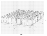
- FIG 1 is shown a schematic illustration of a number of magnetic modules used in a frying hob arrangement according to the present invention.
- Each magnetic module includes two magnetic field generators.
- Each magnet field generator includes a U-shaped magnetic core 1 provided with two magnetic coils 2 and each magnetic field generator has two free ends 6 (only some are indicated in the figure).
- figure 1 is arranged three rows of magnetic modules with four modules in each row.
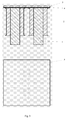
- Figure 2 shows, from below, a schematic illustration of a number of magnetic modules as shown in figure 1.
- Figure 3 shows a cross-sectional view and a view from above of one magnetic module according to present invention.
- a heating means comprising a planar sheet that includes an upper ferromagnetic sheet 5 and a lower paramagnetic sheet 4.
- the magnetic core may, alternatively, have any geometrical form provided that the magnetic core has two free ends in the same plane and that the magnetic core together with the ferromagnetic material to be heated forms a closed magnetic loop.
- a V-shaped core an asymmetrical U-shaped core.
- the magnetic core may consist of laminated silicon sheets, e.g. so called transformer core sheet, or loose powder sintered magnetic material.
- the metal to be heated is placed on or close to the magnetic field generators.
- the magnetic modules are in direct contact to the metal part of ferromagnetic material to be heated.
- an air-gap or a sheet made of a dielectrical material defining a predetermined distance between the magnetic modules and the metal part to be heated.
- the thickness of the air-gap (or the dielectrical sheet) is determined in relation to the intended application of the heating device. Generally, the square of the thickness of the air-gap influences the total thickness of the metal part (the thickness of the metal sheets) up to a maximum total thickness (air-gap and metal part) of 90 mm, given an air-gap of 9 mm.
- an air-gap of 1 or 2 mm was chosen in combination with a ferromagnetic material, e.g. iron, of 4 mm and a paramagnetic material (aluminium) of 2 mm.
- a ferromagnetic material e.g. iron
- a paramagnetic material aluminium
- the metal part to be heated is a ferromagnetic material, e.g. iron, cast iron, magnetic stainless steel and all alloys that include iron.
- the metal part has the form of a heating means, preferably a planar sheet, permanently arranged on or close to the free ends of the magnetic cores of the magnetic modules.
- a heating means preferably a planar sheet
- This group of embodiments have many different applications, e.g. in frying hob arrangements where the planar sheet of iron is used as a frying surface.
- the main application of the present invention is a planar frying hob a number of close-related variants are possible. Among those may be mentioned arranging a specific texture or pattern on the sheet, or giving the sheet a curved shape enabling making hot sandwiches etc.
- the metal part in the form of a planar sheet means preferably comprises two sheets, one upper sheet of a ferromagnetic material, e.g. iron, and a lower sheet of a paramagnetic material, e.g. aluminium.
- a ferromagnetic material e.g. iron
- a paramagnetic material e.g. aluminium
- the metal part in the form of a planar sheet may also comprise only a single sheet made from a ferromagnetic material.
- the combination of ferromagnetic and paramagnetic materials for the sheets constituting the heating means may vary both regarding the choice of material and the thickness of the sheet.
- a paramagnetic material and a magnetic material the advantage is achieved that the paramagnetic material has a repelling effect, i.e. the H-field is symmetrically spread in the sheets that contribute to the even heating of the heating means.
- the combination of the paramagnetic and ferromagnetic materials also obtains a shield that prevents the electromagnetic field to be spread.
- the planar heating means e.g. two metal sheets, are arranged in a plane defined by the free ends of the magnetic cores of the magnetic modules.
- the lower sheet is a 2 mm sheet of aluminium and the upper sheet is a 4 mm sheet of iron.
- the two sheets are floating with respect to each other, i.e. they are not fastened (fixed) to each other in order to avoid material stresses related to the different thermal expansions.
- an air-gap may be provided for between the free ends of the magnetic cores and the planar sheet means.
- a dielectric sheet e.g. silicone, may be arranged in the air gap with the purpose of obtaining a thermal insulation of the magnetic modules from the heat generated in the metal part.
- the magnetic coils are arranged at the magnetic cores.
- one or many magnetic coils are arranged at the core.
- Advantageously two coils are used on each core.
- only one coil may be used on the core arranged e.g. on the lower part of the U-shaped core or on one of the legs, three or more coils may also be arranged at different locations on the core.
- all different arrangements must be separately tuned, e.g. with regard to fed electrical energy.
- Figures 1-3 schematically illustrate how the magnet coils may be arranged on the U-shaped magnetic cores.
- the even heating is achieved essentially because of, firstly that magnet cores have a cross-sectional area that correspond, in relation to the length of each coil and the number of turns of the wire, with the maximum use of the produced magnetic field B max .
- the second reason is that the area of the winding of the coil then is calculated such that the maximal current through the coil is obtained without having so high current density that the heating-losses increase which in its turn results in that the thermal efficiency of the planar heating means, e.g. the frying hob, is lowered.
- FIG. 4 is an illustration of the heating device that includes one magnetic module and provided with a heating means that comprises a dielectrical sheet 3, a paramagnetic sheet 4 and a ferromagnetic sheet 5.
- a heating means that comprises a dielectrical sheet 3, a paramagnetic sheet 4 and a ferromagnetic sheet 5.
- an energy feeding means adapted to feed electrical energy to the coils of the module, control means that controls the feeding means in accordance to input signals received from a control panel where an operator may input various parameters related to the heating, e.g. desired target temperature, heating rate etc.
- a temperature sensor 7 is arranged beneath the ferromagnetic sheet. The temperature sensor generates a temperature signal to the control means in order to increase the accuracy in the control of the heating device. The temperature sensor is further discussed below.
- Temperature sensors are preferably arranged beneath the frying surface, more particular between the ferromagnetic sheet and the paramagnetic sheet. Experiments performed by the inventor show that one sensor per magnetic module give an accurate temperature control.
- the sensor is arranged in a central location of the magnetic module, and is schematically indicated in figure 4. It would also be possible to use more sensors if the application requires an even more accurate temperature control.
- the temperature sensor used in the present invention is preferably a thermo couple element sensor (e.g. type K), which is a passive sensor provided with two thin wires of different materials that generates a direct current in dependence of the temperature. This type of sensors have a fast response time, e.g. in the order of 50 ms and are also be heat resistant up to at least 1000 degrees.
- FIG. 5 is an illustration of the electrical energy feeding of one magnetic module that is schematically shown from above to the right in the figure where the numbers 1-4 designate the four magnetic coils.
- Each magnetic module is provided with two connections f1 and f2, where f1 is connected to the input of three of the coils and f2 is connected to the output of these three coils.
- connection f2 is connected to the input and f1 to the output.
- f1 and f2 are preferably connected to two phases in a three-phase system.
- In order to achieve a symmetrical load preferably 3, 6, 9 etc. magnetic modules are connected to the power source so that no phase shifting is induced resulting in the generation of reactive power.
- each coil could be separately fed instead and in that case the correct polarity for each coil should be controlled by the control means.
- two of the coils are connected by reversed/switched polarities.
- the frequency of the electrical power generated by the power source and applied to the magnetic modules is preferably in the range of 50-60 Hz. However, a much wider frequency range, e.g. 10-500 Hz, is naturally possible to use including the frequencies 16 2/3 Hz and 400 Hz.
- Still another possibility is to use an even higher frequency, in the order of some kHz.
- One problem when using a higher frequency is the heat generated by the coils. By applying the magnetic field generating energy by using pulses of high frequency power the heating of the coils is easily reduced.
- a so-called controlled disconnection of the magnetic modules is applied.
- This controlled disconnection is controlled by the control means and provides that the disconnection is made exactly at or close to a zero crossing of the magnetic field generating energy which results in that no magnetic reminiscence remains.
- Figures 6-9 schematically illustrate the magnetic field deflections in a magnetic module that is fed with energy by using the circuitry illustrated in figure 5.
- Figures 6 and 7 show a magnetic module from above and illustrate the magnetic fields in the plane of the heating means.
- the right coil of the upper magnetic field generator is fed with reversed polarity compared to the other coils.
- the situation at the phase position 90 degrees is illustrated showing the magnetic field in the upper right core is directed inwards and downwards (see figure 8).
- the magnetic fields for the other cores are directed outwards and upwards (see figures 8 and 9).
- figure 7 the situation at the phase position 270 degrees is illustrated where the directions of all magnetic fields are reversed as compared to figure 6.
- the frying hob arrangement according to the present invention is primarily intended for use in restaurant kitchens where high frying capacity is of greatest importance.
- the meat to be fried is put directly on the frying surface when the surface is heated to an appropriate temperature.
- the ferromagnetic sheet constituting the frying surface may advantageously be coated by some suitable coating material especially adapted for the special requirements in this application e.g. with regard to protection against scratches.
- a control panel including an information display showing the temperature etc., input means, e.g. knobs, for setting various parameters related to the heating, e.g. the heating rate and the target temperature.
Landscapes
- Physics & Mathematics (AREA)
- Electromagnetism (AREA)
- General Induction Heating (AREA)
- Magnetic Heads (AREA)
- Magnetic Treatment Devices (AREA)
- Surface Acoustic Wave Elements And Circuit Networks Thereof (AREA)
- General Preparation And Processing Of Foods (AREA)
- Massaging Devices (AREA)
Priority Applications (6)
| Application Number | Priority Date | Filing Date | Title |
|---|---|---|---|
| EP02102386A EP1404155B1 (fr) | 2002-09-26 | 2002-09-26 | Plaque de cuisson à induction |
| AT02102386T ATE313238T1 (de) | 2002-09-26 | 2002-09-26 | Induktive kochfeld-vorrichtung |
| DE60208031T DE60208031T2 (de) | 2002-09-26 | 2002-09-26 | Induktive Kochfeld-Vorrichtung |
| PCT/SE2003/001470 WO2004030413A1 (fr) | 2002-09-26 | 2003-09-22 | Dispositif de friture |
| AU2003265036A AU2003265036A1 (en) | 2002-09-26 | 2003-09-22 | Frying hob arrangement |
| US10/529,484 US7126095B2 (en) | 2002-09-26 | 2003-09-22 | Frying hob arrangement with induction heating |
Applications Claiming Priority (1)
| Application Number | Priority Date | Filing Date | Title |
|---|---|---|---|
| EP02102386A EP1404155B1 (fr) | 2002-09-26 | 2002-09-26 | Plaque de cuisson à induction |
Publications (2)
| Publication Number | Publication Date |
|---|---|
| EP1404155A1 true EP1404155A1 (fr) | 2004-03-31 |
| EP1404155B1 EP1404155B1 (fr) | 2005-12-14 |
Family
ID=31970449
Family Applications (1)
| Application Number | Title | Priority Date | Filing Date |
|---|---|---|---|
| EP02102386A Expired - Lifetime EP1404155B1 (fr) | 2002-09-26 | 2002-09-26 | Plaque de cuisson à induction |
Country Status (6)
| Country | Link |
|---|---|
| US (1) | US7126095B2 (fr) |
| EP (1) | EP1404155B1 (fr) |
| AT (1) | ATE313238T1 (fr) |
| AU (1) | AU2003265036A1 (fr) |
| DE (1) | DE60208031T2 (fr) |
| WO (1) | WO2004030413A1 (fr) |
Cited By (3)
| Publication number | Priority date | Publication date | Assignee | Title |
|---|---|---|---|---|
| WO2006111701A1 (fr) | 2005-04-21 | 2006-10-26 | Lmk Thermosafe Limited | Appareil de chauffage |
| US20090020526A1 (en) * | 2005-12-27 | 2009-01-22 | Fagorbrandt Sas | Induction device comprising multiple individual coils for induction heating plates |
| WO2017093168A1 (fr) * | 2015-12-01 | 2017-06-08 | Arcelik Anonim Sirketi | Unité de bobines d'induction |
Families Citing this family (8)
| Publication number | Priority date | Publication date | Assignee | Title |
|---|---|---|---|---|
| ES2271188T3 (es) * | 2002-09-26 | 2007-04-16 | Mtech Holding Ab | Dispositivo de calentamiento magnetico. |
| WO2006032292A1 (fr) * | 2004-09-23 | 2006-03-30 | E.G.O. Elektro-Gerätebau GmbH | Dispositif de chauffage pour un chauffage plan, pourvu d'elements chauffants a induction |
| JP2008071982A (ja) * | 2006-09-15 | 2008-03-27 | Hitachi Industrial Equipment Systems Co Ltd | 変圧器 |
| CN102471142B (zh) * | 2009-08-17 | 2016-02-24 | Bsh家用电器有限公司 | 具有以金属涂敷的盖板的感应式加热烧煮盘 |
| FR2954661A1 (fr) * | 2009-12-23 | 2011-06-24 | Jaeger | Inducteurs sur phases equilibrees |
| CN106618149A (zh) * | 2010-07-15 | 2017-05-10 | 布瑞威利私人有限公司 | 多功能烹调器 |
| US20160014849A1 (en) * | 2013-01-14 | 2016-01-14 | Breville Pty Limited | Multi Cooker |
| US10085584B2 (en) | 2014-06-09 | 2018-10-02 | Whirlpool Corporation | Method of regulating temperature for sous vide cooking and apparatus therefor |
Citations (6)
| Publication number | Priority date | Publication date | Assignee | Title |
|---|---|---|---|---|
| US3187151A (en) * | 1963-04-04 | 1965-06-01 | Baermann Max | Eddy current heating device |
| GB1157711A (en) * | 1966-10-24 | 1969-07-09 | Electricity Council | Improvements in or relating to Electrical Cooking apparatus and Utensils for use therewith |
| US3980858A (en) * | 1973-08-22 | 1976-09-14 | Mitsubishi Denki Kabushiki Kaisha | Exciter for induction heating apparatus |
| US5053593A (en) * | 1989-01-23 | 1991-10-01 | Nikko Corporation Ltd. | Low-frequency electromagnetic induction heater |
| EP0459837A2 (fr) * | 1990-06-01 | 1991-12-04 | Lennart A. Alfredeen | Dispositif électromagnétique pour le chauffage d'éléments métalliques |
| WO2001078458A1 (fr) * | 2000-04-11 | 2001-10-18 | Light Sciences Corporation | Utilisation d'un element mobile pour la production de chaleur |
Family Cites Families (3)
| Publication number | Priority date | Publication date | Assignee | Title |
|---|---|---|---|---|
| FR2608348B1 (fr) * | 1986-12-10 | 1993-11-12 | Electricite De France | Appareil electrique de cuisson par induction a emission d'harmoniques reduite |
| US5134265A (en) * | 1990-02-16 | 1992-07-28 | Metcal, Inc. | Rapid heating, uniform, highly efficient griddle |
| US5304767A (en) * | 1992-11-13 | 1994-04-19 | Gas Research Institute | Low emission induction heating coil |
-
2002
- 2002-09-26 DE DE60208031T patent/DE60208031T2/de not_active Expired - Lifetime
- 2002-09-26 EP EP02102386A patent/EP1404155B1/fr not_active Expired - Lifetime
- 2002-09-26 AT AT02102386T patent/ATE313238T1/de not_active IP Right Cessation
-
2003
- 2003-09-22 WO PCT/SE2003/001470 patent/WO2004030413A1/fr not_active Application Discontinuation
- 2003-09-22 AU AU2003265036A patent/AU2003265036A1/en not_active Abandoned
- 2003-09-22 US US10/529,484 patent/US7126095B2/en not_active Expired - Fee Related
Patent Citations (6)
| Publication number | Priority date | Publication date | Assignee | Title |
|---|---|---|---|---|
| US3187151A (en) * | 1963-04-04 | 1965-06-01 | Baermann Max | Eddy current heating device |
| GB1157711A (en) * | 1966-10-24 | 1969-07-09 | Electricity Council | Improvements in or relating to Electrical Cooking apparatus and Utensils for use therewith |
| US3980858A (en) * | 1973-08-22 | 1976-09-14 | Mitsubishi Denki Kabushiki Kaisha | Exciter for induction heating apparatus |
| US5053593A (en) * | 1989-01-23 | 1991-10-01 | Nikko Corporation Ltd. | Low-frequency electromagnetic induction heater |
| EP0459837A2 (fr) * | 1990-06-01 | 1991-12-04 | Lennart A. Alfredeen | Dispositif électromagnétique pour le chauffage d'éléments métalliques |
| WO2001078458A1 (fr) * | 2000-04-11 | 2001-10-18 | Light Sciences Corporation | Utilisation d'un element mobile pour la production de chaleur |
Cited By (3)
| Publication number | Priority date | Publication date | Assignee | Title |
|---|---|---|---|---|
| WO2006111701A1 (fr) | 2005-04-21 | 2006-10-26 | Lmk Thermosafe Limited | Appareil de chauffage |
| US20090020526A1 (en) * | 2005-12-27 | 2009-01-22 | Fagorbrandt Sas | Induction device comprising multiple individual coils for induction heating plates |
| WO2017093168A1 (fr) * | 2015-12-01 | 2017-06-08 | Arcelik Anonim Sirketi | Unité de bobines d'induction |
Also Published As
| Publication number | Publication date |
|---|---|
| DE60208031D1 (de) | 2006-01-19 |
| WO2004030413A1 (fr) | 2004-04-08 |
| AU2003265036A1 (en) | 2004-04-19 |
| EP1404155B1 (fr) | 2005-12-14 |
| US20060118547A1 (en) | 2006-06-08 |
| ATE313238T1 (de) | 2005-12-15 |
| US7126095B2 (en) | 2006-10-24 |
| DE60208031T2 (de) | 2006-08-31 |
Similar Documents
| Publication | Publication Date | Title |
|---|---|---|
| EP1404154B1 (fr) | Dispositif de chauffage magnétique | |
| CA2597530C (fr) | Dispositif de chauffage par induction pour une plaque metallique | |
| RU2431946C2 (ru) | Устройство индукционного нагрева | |
| EP0459837B1 (fr) | Dispositif électromagnétique pour le chauffage d'éléments métalliques | |
| US7049563B2 (en) | Induction cooker with heating coil and electrical conductor | |
| EP1404155B1 (fr) | Plaque de cuisson à induction | |
| EP2048914B1 (fr) | Dispositif de cuisson doté d'un élément de chauffage par induction | |
| GB1436221A (en) | Induction heating apparatus | |
| JP5943683B2 (ja) | 誘導加熱装置 | |
| WO2015094482A1 (fr) | Saturation périphérique cc de bande chauffante à flux transversal | |
| KR101949562B1 (ko) | 유도 가열 장치 | |
| EP0748577B1 (fr) | Element chauffant par induction | |
| CN100474985C (zh) | 用于横向磁通感应加热伸长金属工件形式的物体的线圈 | |
| WO2017093168A1 (fr) | Unité de bobines d'induction | |
| EP1582627A1 (fr) | Dispositif de chauffage pour rail | |
| US20190297923A1 (en) | Induction heating and cooking | |
| WO2009067226A2 (fr) | Inducteur passif pour une commande améliorée dans le chauffage localisé de corps minces | |
| JP2003187951A (ja) | 板幅方向の均温性に優れた金属帯板の加熱装置 | |
| JP5148439B2 (ja) | 誘導加熱装置 | |
| JP3869892B2 (ja) | 電磁誘導加熱用コイル | |
| JP2021077536A (ja) | 電磁誘導加熱装置 | |
| JPH10335056A (ja) | 電磁誘導加熱用コイル | |
| WO2000035250A1 (fr) | Unite de chauffage par induction, et ensemble comportant ladite unite | |
| JPH08273818A (ja) | 誘導加熱コイル及び誘導加熱炊飯器 | |
| JPH08273821A (ja) | 誘導加熱器具 |
Legal Events
| Date | Code | Title | Description |
|---|---|---|---|
| PUAI | Public reference made under article 153(3) epc to a published international application that has entered the european phase |
Free format text: ORIGINAL CODE: 0009012 |
|
| AK | Designated contracting states |
Kind code of ref document: A1 Designated state(s): AT BE BG CH CY CZ DE DK EE ES FI FR GB GR IE IT LI LU MC NL PT SE SK TR |
|
| AX | Request for extension of the european patent |
Extension state: AL LT LV MK RO SI |
|
| 17P | Request for examination filed |
Effective date: 20040904 |
|
| 17Q | First examination report despatched |
Effective date: 20040929 |
|
| AKX | Designation fees paid |
Designated state(s): AT BE BG CH CY CZ DE DK EE ES FI FR GB GR IE IT LI LU MC NL PT SE SK TR |
|
| GRAP | Despatch of communication of intention to grant a patent |
Free format text: ORIGINAL CODE: EPIDOSNIGR1 |
|
| RAP1 | Party data changed (applicant data changed or rights of an application transferred) |
Owner name: ALFREDEEN, LENNART |
|
| RIN1 | Information on inventor provided before grant (corrected) |
Inventor name: ALFREDEEN, LENNART |
|
| RAP1 | Party data changed (applicant data changed or rights of an application transferred) |
Owner name: MTECH HOLDING AB |
|
| RIN1 | Information on inventor provided before grant (corrected) |
Inventor name: ALFREDEEN, LENNART |
|
| RIN1 | Information on inventor provided before grant (corrected) |
Inventor name: ALFREDEEN, LENNART |
|
| GRAS | Grant fee paid |
Free format text: ORIGINAL CODE: EPIDOSNIGR3 |
|
| GRAA | (expected) grant |
Free format text: ORIGINAL CODE: 0009210 |
|
| AK | Designated contracting states |
Kind code of ref document: B1 Designated state(s): AT BE BG CH CY CZ DE DK EE ES FI FR GB GR IE IT LI LU MC NL PT SE SK TR |
|
| PG25 | Lapsed in a contracting state [announced via postgrant information from national office to epo] |
Ref country code: CZ Free format text: LAPSE BECAUSE OF FAILURE TO SUBMIT A TRANSLATION OF THE DESCRIPTION OR TO PAY THE FEE WITHIN THE PRESCRIBED TIME-LIMIT Effective date: 20051214 Ref country code: BE Free format text: LAPSE BECAUSE OF FAILURE TO SUBMIT A TRANSLATION OF THE DESCRIPTION OR TO PAY THE FEE WITHIN THE PRESCRIBED TIME-LIMIT Effective date: 20051214 Ref country code: AT Free format text: LAPSE BECAUSE OF FAILURE TO SUBMIT A TRANSLATION OF THE DESCRIPTION OR TO PAY THE FEE WITHIN THE PRESCRIBED TIME-LIMIT Effective date: 20051214 Ref country code: SK Free format text: LAPSE BECAUSE OF FAILURE TO SUBMIT A TRANSLATION OF THE DESCRIPTION OR TO PAY THE FEE WITHIN THE PRESCRIBED TIME-LIMIT Effective date: 20051214 Ref country code: LI Free format text: LAPSE BECAUSE OF FAILURE TO SUBMIT A TRANSLATION OF THE DESCRIPTION OR TO PAY THE FEE WITHIN THE PRESCRIBED TIME-LIMIT Effective date: 20051214 Ref country code: CH Free format text: LAPSE BECAUSE OF FAILURE TO SUBMIT A TRANSLATION OF THE DESCRIPTION OR TO PAY THE FEE WITHIN THE PRESCRIBED TIME-LIMIT Effective date: 20051214 Ref country code: NL Free format text: LAPSE BECAUSE OF FAILURE TO SUBMIT A TRANSLATION OF THE DESCRIPTION OR TO PAY THE FEE WITHIN THE PRESCRIBED TIME-LIMIT Effective date: 20051214 |
|
| REG | Reference to a national code |
Ref country code: GB Ref legal event code: FG4D |
|
| REG | Reference to a national code |
Ref country code: CH Ref legal event code: EP |
|
| REG | Reference to a national code |
Ref country code: IE Ref legal event code: FG4D |
|
| REF | Corresponds to: |
Ref document number: 60208031 Country of ref document: DE Date of ref document: 20060119 Kind code of ref document: P |
|
| PG25 | Lapsed in a contracting state [announced via postgrant information from national office to epo] |
Ref country code: BG Free format text: LAPSE BECAUSE OF FAILURE TO SUBMIT A TRANSLATION OF THE DESCRIPTION OR TO PAY THE FEE WITHIN THE PRESCRIBED TIME-LIMIT Effective date: 20060314 Ref country code: DK Free format text: LAPSE BECAUSE OF FAILURE TO SUBMIT A TRANSLATION OF THE DESCRIPTION OR TO PAY THE FEE WITHIN THE PRESCRIBED TIME-LIMIT Effective date: 20060314 Ref country code: GR Free format text: LAPSE BECAUSE OF FAILURE TO SUBMIT A TRANSLATION OF THE DESCRIPTION OR TO PAY THE FEE WITHIN THE PRESCRIBED TIME-LIMIT Effective date: 20060314 |
|
| PG25 | Lapsed in a contracting state [announced via postgrant information from national office to epo] |
Ref country code: ES Free format text: LAPSE BECAUSE OF FAILURE TO SUBMIT A TRANSLATION OF THE DESCRIPTION OR TO PAY THE FEE WITHIN THE PRESCRIBED TIME-LIMIT Effective date: 20060325 |
|
| REG | Reference to a national code |
Ref country code: SE Ref legal event code: TRGR |
|
| PG25 | Lapsed in a contracting state [announced via postgrant information from national office to epo] |
Ref country code: PT Free format text: LAPSE BECAUSE OF FAILURE TO SUBMIT A TRANSLATION OF THE DESCRIPTION OR TO PAY THE FEE WITHIN THE PRESCRIBED TIME-LIMIT Effective date: 20060515 |
|
| NLV1 | Nl: lapsed or annulled due to failure to fulfill the requirements of art. 29p and 29m of the patents act | ||
| REG | Reference to a national code |
Ref country code: CH Ref legal event code: PL |
|
| PG25 | Lapsed in a contracting state [announced via postgrant information from national office to epo] |
Ref country code: IE Free format text: LAPSE BECAUSE OF NON-PAYMENT OF DUE FEES Effective date: 20060926 |
|
| PG25 | Lapsed in a contracting state [announced via postgrant information from national office to epo] |
Ref country code: MC Free format text: LAPSE BECAUSE OF NON-PAYMENT OF DUE FEES Effective date: 20060930 |
|
| PLBE | No opposition filed within time limit |
Free format text: ORIGINAL CODE: 0009261 |
|
| STAA | Information on the status of an ep patent application or granted ep patent |
Free format text: STATUS: NO OPPOSITION FILED WITHIN TIME LIMIT |
|
| 26N | No opposition filed |
Effective date: 20060915 |
|
| EN | Fr: translation not filed | ||
| PG25 | Lapsed in a contracting state [announced via postgrant information from national office to epo] |
Ref country code: FR Free format text: LAPSE BECAUSE OF FAILURE TO SUBMIT A TRANSLATION OF THE DESCRIPTION OR TO PAY THE FEE WITHIN THE PRESCRIBED TIME-LIMIT Effective date: 20070202 |
|
| PG25 | Lapsed in a contracting state [announced via postgrant information from national office to epo] |
Ref country code: EE Free format text: LAPSE BECAUSE OF FAILURE TO SUBMIT A TRANSLATION OF THE DESCRIPTION OR TO PAY THE FEE WITHIN THE PRESCRIBED TIME-LIMIT Effective date: 20051214 |
|
| PG25 | Lapsed in a contracting state [announced via postgrant information from national office to epo] |
Ref country code: TR Free format text: LAPSE BECAUSE OF FAILURE TO SUBMIT A TRANSLATION OF THE DESCRIPTION OR TO PAY THE FEE WITHIN THE PRESCRIBED TIME-LIMIT Effective date: 20051214 Ref country code: LU Free format text: LAPSE BECAUSE OF NON-PAYMENT OF DUE FEES Effective date: 20060926 |
|
| PG25 | Lapsed in a contracting state [announced via postgrant information from national office to epo] |
Ref country code: FR Free format text: LAPSE BECAUSE OF FAILURE TO SUBMIT A TRANSLATION OF THE DESCRIPTION OR TO PAY THE FEE WITHIN THE PRESCRIBED TIME-LIMIT Effective date: 20051214 Ref country code: CY Free format text: LAPSE BECAUSE OF FAILURE TO SUBMIT A TRANSLATION OF THE DESCRIPTION OR TO PAY THE FEE WITHIN THE PRESCRIBED TIME-LIMIT Effective date: 20051214 |
|
| PGFP | Annual fee paid to national office [announced via postgrant information from national office to epo] |
Ref country code: DE Payment date: 20100927 Year of fee payment: 9 |
|
| PGFP | Annual fee paid to national office [announced via postgrant information from national office to epo] |
Ref country code: FI Payment date: 20110920 Year of fee payment: 10 Ref country code: GB Payment date: 20110928 Year of fee payment: 10 |
|
| PGFP | Annual fee paid to national office [announced via postgrant information from national office to epo] |
Ref country code: IT Payment date: 20110914 Year of fee payment: 10 |
|
| PG25 | Lapsed in a contracting state [announced via postgrant information from national office to epo] |
Ref country code: FI Free format text: LAPSE BECAUSE OF NON-PAYMENT OF DUE FEES Effective date: 20120926 |
|
| GBPC | Gb: european patent ceased through non-payment of renewal fee |
Effective date: 20120926 |
|
| PG25 | Lapsed in a contracting state [announced via postgrant information from national office to epo] |
Ref country code: GB Free format text: LAPSE BECAUSE OF NON-PAYMENT OF DUE FEES Effective date: 20120926 Ref country code: DE Free format text: LAPSE BECAUSE OF NON-PAYMENT OF DUE FEES Effective date: 20130403 |
|
| PG25 | Lapsed in a contracting state [announced via postgrant information from national office to epo] |
Ref country code: IT Free format text: LAPSE BECAUSE OF NON-PAYMENT OF DUE FEES Effective date: 20120926 |
|
| REG | Reference to a national code |
Ref country code: DE Ref legal event code: R119 Ref document number: 60208031 Country of ref document: DE Effective date: 20130403 |
|
| PGFP | Annual fee paid to national office [announced via postgrant information from national office to epo] |
Ref country code: SE Payment date: 20190329 Year of fee payment: 17 |
|
| PG25 | Lapsed in a contracting state [announced via postgrant information from national office to epo] |
Ref country code: SE Free format text: LAPSE BECAUSE OF NON-PAYMENT OF DUE FEES Effective date: 20190927 |
|
| REG | Reference to a national code |
Ref country code: SE Ref legal event code: EUG |