EP1403593A2 - Water heater - Google Patents
Water heater Download PDFInfo
- Publication number
- EP1403593A2 EP1403593A2 EP03021843A EP03021843A EP1403593A2 EP 1403593 A2 EP1403593 A2 EP 1403593A2 EP 03021843 A EP03021843 A EP 03021843A EP 03021843 A EP03021843 A EP 03021843A EP 1403593 A2 EP1403593 A2 EP 1403593A2
- Authority
- EP
- European Patent Office
- Prior art keywords
- reservoir
- heating means
- water
- boiler
- heating
- Prior art date
- Legal status (The legal status is an assumption and is not a legal conclusion. Google has not performed a legal analysis and makes no representation as to the accuracy of the status listed.)
- Withdrawn
Links
Images


Classifications
-
- F—MECHANICAL ENGINEERING; LIGHTING; HEATING; WEAPONS; BLASTING
- F28—HEAT EXCHANGE IN GENERAL
- F28D—HEAT-EXCHANGE APPARATUS, NOT PROVIDED FOR IN ANOTHER SUBCLASS, IN WHICH THE HEAT-EXCHANGE MEDIA DO NOT COME INTO DIRECT CONTACT
- F28D20/00—Heat storage plants or apparatus in general; Regenerative heat-exchange apparatus not covered by groups F28D17/00 or F28D19/00
- F28D20/0034—Heat storage plants or apparatus in general; Regenerative heat-exchange apparatus not covered by groups F28D17/00 or F28D19/00 using liquid heat storage material
-
- F—MECHANICAL ENGINEERING; LIGHTING; HEATING; WEAPONS; BLASTING
- F24—HEATING; RANGES; VENTILATING
- F24D—DOMESTIC- OR SPACE-HEATING SYSTEMS, e.g. CENTRAL HEATING SYSTEMS; DOMESTIC HOT-WATER SUPPLY SYSTEMS; ELEMENTS OR COMPONENTS THEREFOR
- F24D17/00—Domestic hot-water supply systems
- F24D17/0073—Arrangements for preventing the occurrence or proliferation of microorganisms in the water
-
- F—MECHANICAL ENGINEERING; LIGHTING; HEATING; WEAPONS; BLASTING
- F24—HEATING; RANGES; VENTILATING
- F24H—FLUID HEATERS, e.g. WATER OR AIR HEATERS, HAVING HEAT-GENERATING MEANS, e.g. HEAT PUMPS, IN GENERAL
- F24H1/00—Water heaters, e.g. boilers, continuous-flow heaters or water-storage heaters
- F24H1/18—Water-storage heaters
- F24H1/20—Water-storage heaters with immersed heating elements, e.g. electric elements or furnace tubes
-
- F—MECHANICAL ENGINEERING; LIGHTING; HEATING; WEAPONS; BLASTING
- F24—HEATING; RANGES; VENTILATING
- F24D—DOMESTIC- OR SPACE-HEATING SYSTEMS, e.g. CENTRAL HEATING SYSTEMS; DOMESTIC HOT-WATER SUPPLY SYSTEMS; ELEMENTS OR COMPONENTS THEREFOR
- F24D3/00—Hot-water central heating systems
- F24D3/08—Hot-water central heating systems in combination with systems for domestic hot-water supply
- F24D3/082—Hot water storage tanks specially adapted therefor
-
- F—MECHANICAL ENGINEERING; LIGHTING; HEATING; WEAPONS; BLASTING
- F24—HEATING; RANGES; VENTILATING
- F24H—FLUID HEATERS, e.g. WATER OR AIR HEATERS, HAVING HEAT-GENERATING MEANS, e.g. HEAT PUMPS, IN GENERAL
- F24H1/00—Water heaters, e.g. boilers, continuous-flow heaters or water-storage heaters
- F24H1/18—Water-storage heaters
- F24H1/20—Water-storage heaters with immersed heating elements, e.g. electric elements or furnace tubes
- F24H1/201—Water-storage heaters with immersed heating elements, e.g. electric elements or furnace tubes using electric energy supply
- F24H1/202—Water-storage heaters with immersed heating elements, e.g. electric elements or furnace tubes using electric energy supply with resistances
-
- F—MECHANICAL ENGINEERING; LIGHTING; HEATING; WEAPONS; BLASTING
- F24—HEATING; RANGES; VENTILATING
- F24H—FLUID HEATERS, e.g. WATER OR AIR HEATERS, HAVING HEAT-GENERATING MEANS, e.g. HEAT PUMPS, IN GENERAL
- F24H1/00—Water heaters, e.g. boilers, continuous-flow heaters or water-storage heaters
- F24H1/18—Water-storage heaters
- F24H1/20—Water-storage heaters with immersed heating elements, e.g. electric elements or furnace tubes
- F24H1/208—Water-storage heaters with immersed heating elements, e.g. electric elements or furnace tubes with tubes filled with heat transfer fluid
-
- F—MECHANICAL ENGINEERING; LIGHTING; HEATING; WEAPONS; BLASTING
- F28—HEAT EXCHANGE IN GENERAL
- F28D—HEAT-EXCHANGE APPARATUS, NOT PROVIDED FOR IN ANOTHER SUBCLASS, IN WHICH THE HEAT-EXCHANGE MEDIA DO NOT COME INTO DIRECT CONTACT
- F28D20/00—Heat storage plants or apparatus in general; Regenerative heat-exchange apparatus not covered by groups F28D17/00 or F28D19/00
- F28D2020/0065—Details, e.g. particular heat storage tanks, auxiliary members within tanks
- F28D2020/0069—Distributing arrangements; Fluid deflecting means
-
- F—MECHANICAL ENGINEERING; LIGHTING; HEATING; WEAPONS; BLASTING
- F28—HEAT EXCHANGE IN GENERAL
- F28D—HEAT-EXCHANGE APPARATUS, NOT PROVIDED FOR IN ANOTHER SUBCLASS, IN WHICH THE HEAT-EXCHANGE MEDIA DO NOT COME INTO DIRECT CONTACT
- F28D20/00—Heat storage plants or apparatus in general; Regenerative heat-exchange apparatus not covered by groups F28D17/00 or F28D19/00
- F28D2020/0065—Details, e.g. particular heat storage tanks, auxiliary members within tanks
- F28D2020/0078—Heat exchanger arrangements
-
- Y—GENERAL TAGGING OF NEW TECHNOLOGICAL DEVELOPMENTS; GENERAL TAGGING OF CROSS-SECTIONAL TECHNOLOGIES SPANNING OVER SEVERAL SECTIONS OF THE IPC; TECHNICAL SUBJECTS COVERED BY FORMER USPC CROSS-REFERENCE ART COLLECTIONS [XRACs] AND DIGESTS
- Y02—TECHNOLOGIES OR APPLICATIONS FOR MITIGATION OR ADAPTATION AGAINST CLIMATE CHANGE
- Y02B—CLIMATE CHANGE MITIGATION TECHNOLOGIES RELATED TO BUILDINGS, e.g. HOUSING, HOUSE APPLIANCES OR RELATED END-USER APPLICATIONS
- Y02B10/00—Integration of renewable energy sources in buildings
- Y02B10/20—Solar thermal
-
- Y—GENERAL TAGGING OF NEW TECHNOLOGICAL DEVELOPMENTS; GENERAL TAGGING OF CROSS-SECTIONAL TECHNOLOGIES SPANNING OVER SEVERAL SECTIONS OF THE IPC; TECHNICAL SUBJECTS COVERED BY FORMER USPC CROSS-REFERENCE ART COLLECTIONS [XRACs] AND DIGESTS
- Y02—TECHNOLOGIES OR APPLICATIONS FOR MITIGATION OR ADAPTATION AGAINST CLIMATE CHANGE
- Y02B—CLIMATE CHANGE MITIGATION TECHNOLOGIES RELATED TO BUILDINGS, e.g. HOUSING, HOUSE APPLIANCES OR RELATED END-USER APPLICATIONS
- Y02B10/00—Integration of renewable energy sources in buildings
- Y02B10/70—Hybrid systems, e.g. uninterruptible or back-up power supplies integrating renewable energies
-
- Y—GENERAL TAGGING OF NEW TECHNOLOGICAL DEVELOPMENTS; GENERAL TAGGING OF CROSS-SECTIONAL TECHNOLOGIES SPANNING OVER SEVERAL SECTIONS OF THE IPC; TECHNICAL SUBJECTS COVERED BY FORMER USPC CROSS-REFERENCE ART COLLECTIONS [XRACs] AND DIGESTS
- Y02—TECHNOLOGIES OR APPLICATIONS FOR MITIGATION OR ADAPTATION AGAINST CLIMATE CHANGE
- Y02E—REDUCTION OF GREENHOUSE GAS [GHG] EMISSIONS, RELATED TO ENERGY GENERATION, TRANSMISSION OR DISTRIBUTION
- Y02E60/00—Enabling technologies; Technologies with a potential or indirect contribution to GHG emissions mitigation
- Y02E60/14—Thermal energy storage
-
- Y—GENERAL TAGGING OF NEW TECHNOLOGICAL DEVELOPMENTS; GENERAL TAGGING OF CROSS-SECTIONAL TECHNOLOGIES SPANNING OVER SEVERAL SECTIONS OF THE IPC; TECHNICAL SUBJECTS COVERED BY FORMER USPC CROSS-REFERENCE ART COLLECTIONS [XRACs] AND DIGESTS
- Y02—TECHNOLOGIES OR APPLICATIONS FOR MITIGATION OR ADAPTATION AGAINST CLIMATE CHANGE
- Y02E—REDUCTION OF GREENHOUSE GAS [GHG] EMISSIONS, RELATED TO ENERGY GENERATION, TRANSMISSION OR DISTRIBUTION
- Y02E70/00—Other energy conversion or management systems reducing GHG emissions
- Y02E70/30—Systems combining energy storage with energy generation of non-fossil origin
Landscapes
- Engineering & Computer Science (AREA)
- Physics & Mathematics (AREA)
- Thermal Sciences (AREA)
- Mechanical Engineering (AREA)
- General Engineering & Computer Science (AREA)
- Chemical & Material Sciences (AREA)
- Combustion & Propulsion (AREA)
- Heat-Pump Type And Storage Water Heaters (AREA)
- Instantaneous Water Boilers, Portable Hot-Water Supply Apparatuses, And Control Of Portable Hot-Water Supply Apparatuses (AREA)
Abstract
Description
- The present invention relates to a water heater, or boiler, used to obtain hot water for sanitary water, agricultural, industrial uses, for heating, for swimming pools, etc., of the type comprising a reservoir which contains water at heat.
- Furthermore, the invention relates to a method for the production of such a boiler.
- As known, a boiler used for heating sanitary water in a building, for example a house, can be powered by electricity, gas or solar energy.
- In particular, an electrical boiler makes use of the heat generated by an electrical resistance for heating the water contained in a reservoir.
- The main advantages of an electrical boiler are a low cost and an easy installation, since it is sufficient to connect it to hot/cold water conduits and to turn on the voltage supply. Furthermore, differently from other systems of heat generation, it does not require presence of specialized operators at the moment of installation.
- Alternatively, the heat is obtained either burning a gas, usually methane, in a combustion chamber, or exploiting solar energy by means of suitable panels that absorb the energy turning infrared waves into heat.
- The water contained in the reservoir can be heated either directly, where the heat source is integrated in the boiler, or indirectly through heat exchangers.
- Indirect heating requires heat exchangers in the form of a coil tube, a U-shaped tube or tubes of other shape, in which a heating liquid flows, advantageously water, coming from a reservoir. In this case, the heating tube exchanges heat with the water in the boiler.
- More precisely, the heating duct connected to the heating system, either methane or solar heating, exchanges heat with water coming from a sanitary water network, usually supplied into the boiler at a low part and drawn off at an upper part thereof.
- A problem common to all the types of boilers above cited is power setting. A high power causes higher energy consumption and plant costs, even if the desired temperature is reached in less time. A low power allows to save energy and plant costs, but require more time.
- In particular, solar heating allows high energy saving, but the power cannot be managed like in other systems such as gas or electric heating.
- Mixed plants also exist, where solar power is used for pre-heating the water and cooperates to achieve the desired temperature along with electric power, or gas power, which is summed to the previous. Even in this case, however, the time for having hot water at the desired temperature is related to the overall power available.
- In case of direct heating, either electric or gas heating, the power is supplied when the water temperature contained in the boiler drops below a certain set-point value; a thermostat either turns the electrical resistance on, or supplies gas in the combustion chamber, for returning the water at the set temperature.
- In case of indirect heating, the power is transmitted, usually, by a heating coil tube comprising a plurality of coil turns all of same shape and of equal height arranged in the boiler either for all its height or only in the low part thereof.
- The heating tube raises substantially homogeneously the temperature of all the water contained in the reservoir starting from its contact surface.
- However, the size of the boiler affects the time, at a same power, to reach a desired water temperature. For example, a 500 litres boiler can provide water at 60°C in a time longer than a 200 litres boiler, under a same power. The latter, however, having less capacity, can satisfy only a smaller water demand.
- Furthermore, the boiler is sized for a optimal maximum capacity, even if in many cases the water demand is less than the capacity. For example, a 30 litres boiler, used as water heater for washing dishes of for making single showers can be insufficient for other uses. On the other hand, a 80-90 litres boiler often is used for a hot water demand less than the maximum capacity. In such cases, there is a considerable waste since the boiler maintains the set temperature for all the water in it contained.
- It is therefore a feature of the present invention to provide a boiler for rational exploitation of the heating power and to allow a considerable energy saving.
- It is a particular a feature of the present invention to provide a boiler capable of reducing the time for providing a low amount of hot water without reducing the overall capacity.
- These and other objects are accomplished by the boiler, according to the present invention, comprising:
- a reservoir having a lower portion, a central portion and an upper portion, in which water to heat is supplied through an inlet and drawn off on demand through an outlet by at least an user;
- first heating means suitable for exchanging heat with water supplied in the reservoir at the lower portion, or at the lower and central portions;
- at least second heating means suitable for exchanging heat with water supplied in the reservoir at the upper portion of the reservoir same, near the outlet of the water heated in the reservoir,
- said first heating means raising the water temperature at the water inlet in said reservoir, inducing a slow convection flow that brings the hot water towards said second heating means,
- said second heating means raising quickly the water temperature only at the outlet of the water at the upper part of said reservoir.
- The heating means can be an electrical resistance or a coil tube in which heating liquid flows.
- If said heating means are of electrical type their position can be selected from the group:
- arrangement at side walls of said reservoir;
- arrangement at the lower portion and at the upper
- portion of the reservoir.
- Advantageously, third heating means are provided located between said first and said second heating means at a central portion of said reservoir.
- In a possible exemplary embodiment, a control board is provided to switch heating power selectively to said first heating means, to said second heating means, to both first and second heating means, and in case of three heating means to all and three or to a combination thereof.
- The first, second and third heating means can be coil tube portions in which heating liquid flows hydraulically connected to form a resulting coil tube that crosses said reservoir for all its length, said resulting coil tube having a coil density more concentrated at said first and said second heating means and more sparse at said third heating means.
- In this case, said third heating means has preferably function of connection between said first and said second heating means and is a substantially straight tubular portion.
- Preferably, the apportionment of the exchange surface of each heating means of said resulting coil tube is the following:
- 5÷40% of the overall length of said reservoir for said second heating means;
- 25÷35% of the overall length of the reservoir for said third heating means;
- 5÷50% of the overall length of the reservoir for said first heating means.
- In a preferred exemplary embodiment the apportionment of the exchange surface of each heating means of said resulting coil tube is the following:
- 25÷35% of the overall length of said reservoir for said second heating means;
- 25÷35% of the overall length of the reservoir for said third heating means;
- 35÷45% of the overall length of the reservoir for said first heating means.
- The water heated can be drawn off from said reservoir in a way selected from the group:
- a tube that comes out from said reservoir in its highest point;
- a horizontal tube that comes out from a side wall of the reservoir and an elbow portion that has its open end in the highest point.
- The water that enters in said reservoir has an inlet flow in a way selected from the group:
- a tube with outlet oriented towards the bottom of the reservoir;
- a tube with outlet provided with jet spoiling elements that break turbulent flow in the mass of water at the lower part of the reservoir and then avoids a quick mixing of the hot and cold water.
- The invention will now shown with the following description of exemplary embodiments thereof, exemplifying but not limitative, with reference to the attached drawings wherein:
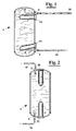
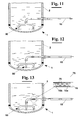
- figure 1 shows diagrammatically in a partially cross sectioned view a first exemplary embodiment of a boiler, according to the invention;
- figures from 2 to 10 show diagrammatically in partially cross sectioned views some possible alternative exemplary embodiments of the boiler of figure 1;
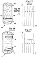
- figures from 11 to 13 show in detail in partially cross sectioned views some possible embodiments of a feeding duct of sanitary water into the boiler that maintain laminar flow of the water in the boiler;
- figures 14 and 15 show two possible exemplary embodiments of an hydraulic circuit coupled to the boiler according to the invention;
- figure 16 shows diagrammatically in a partially cross sectioned view a boiler of prior art with electrical resistance;
- figure 17 shows qualitatively the trend of water temperature in the boiler of figure 16 versus height and time;
- figure 18 shows diagrammatically in a partially cross sectioned view an exemplary embodiment of the boiler, according to the invention;
- figure 19 shows qualitatively the trend of water temperature in the boiler of figure 18 versus height and time;
- figure 20 shows diagrammatically in a partially cross sectioned view a boiler of prior art with coil tube;
- figure 21 shows qualitatively the trend of water temperature in the boiler of figure 20 versus height and time;
- figure 22 shows diagrammatically in a partially cross sectioned view a boiler, according to the invention;
- figure 23 shows qualitatively the trend of water temperature in the boiler of figure 22 versus height and time, when two heating means are operated at the same time.
- With reference to figure 1, a proportional and selective heating boiler, according to the invention, comprises a
reservoir 1 in which sanitary water to be heated is supplied, coming from a water network, through aninlet 2 and aduct 15. In particular, the water that entersreservoir 1 has an inlet flow oriented towards the bottom ofreservoir 1 same. The sanitary water is heated inreservoir 1, by at least a first and a second heating means, for example a couple ofelectrical resistances 10 and 11 (figures 1 and 2), or alternatively, by means of twocoil tubes - The water is, moreover, drawn off
reservoir 1 at the desired temperature from anoutlet 3 and aduct 16 connected to different deliveries, not shown. - In particular, second heating means 10, or 210, is located in the upper portion of
reservoir 1, and precisely nearwater outlet 3. First heating means 11, or 211, is arranged in the lower part of the cylindrical portion of the reservoir nearwater inlet 2. - In case electrical resistances are used, they can be arranged at the bottom and at the top of
reservoir 1, and alsoinlet 2 andoutlet 3 of the sanitary water can be arranged at the bottom and at the top of reservoir 1 (figure 2). - In figure 4 an exemplary embodiment is shown alternative to the previous where a third heating means, for example a
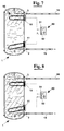
resistance 12, is arranged between the upper heating means 10 and the lower heating means 11. This solution can be provided, for example, in case of large reservoirs or for heating much more water at the upper part ofreservoir 1. - As shown in figures 4 and 5 the third heating means can be a
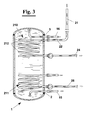
coil tube 212 arranged connected hydraulically tocoil tubes coil tube 215 that crossesreservoir 1 for all its length. In particular, in the case of figure 5 the water is heated by asolar panel 20 whereas in the case shown in figure 6 the heating fluid receives the heat necessary to raise the water temperature ofreservoir 1 by an electrical resistance or by astove 30 supplied with gas or diesel oil. - According to the invention, the
central portion 212 of the resultingcoil tube 215 has less coils than the twoextreme portions extreme portions central portion 212 where the coils are less, a smaller amount of heat is exchanged. The exchange in the lower zone ofreservoir 1 generates, as well known, convection flow that keep the cold water towards below sending the hot water towards the above, causing the upper part atoutlet 3 to have the hottest water. This way hot water at the desired temperature is very quickly available. - As shown in figures from 7 to 10, the heating means can be operatively connected to a
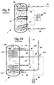
control board 50. This way, by means ofswitches resistances 10 and 11 (figure 8), causing the water ofreservoir 1 to be heated quickly, since the two hatched zones of figures 7 and 8 are both heated directly. - Furthermore, in case of large reservoirs it is possible to turn on at the same time the
third resistance 12 and the first resistance 10 (figure 9) for having a much higher amount of hot water in the upper part ofreservoir 1. - What above said can be made also in case coil tubes in which a heating fluid flows are used as heating means (figure 10).
- Such solution allows a rational exploitation of the energy, since, by suitably adjusting the switches of the control board it is possible to turn on the heating means that allow to bring at a desired temperature only the demanded amount of water. In particular, this case (figure 7) can be applied when only a small amount of water is demanded, for example for a shower or for washing dishes, so that not all the water contained in
reservoir 1 is to be heated. The case, instead, diagrammatically shown in figure 8 occurs when there is need of a significant amount of water, but after a longer time, where the soleupper resistance 10 is not sufficient to heat all the demanded amount of water. - In figures from 11 to 13 some embodiments of the invention are shown that allow to increase water stratification as above described. A first solution provides
jet spoiling elements 90 arranged at the end ofwater feeding duct 15 intoboiler 1. This arrangement avoids that turbulent flow occurs in the mass of water at the lower part ofreservoir 1 and then that hot and cold water mix with each other. - Another arrangement of the invention to assure water stratification in
reservoir 1 is shown in detail inenlargement 75 of figure 13. In this case, the water is supplied toreservoir 1 from aduct 15 having a double tube portion. More in detail,inner duct 15a of the double tube portion has a plurality ofholes 76 that spoil the water jet enteringend portion 15b ofduct 15 and then reservoir 1 (figure 13). - In figure 14 a further exemplary embodiment is shown for
boiler 1. In thiscase duct 16 for drawing water offreservoir 1 and feedingduct 15 are connected by amixer 80 that mixes the inlet and outlet flows in a predetermined way. In particular, the use ofmixer 80 provides mixing the two flows of water in order to supply the deliveries, not shown, with a resultingwater flow 17 at a desired temperature. - A further exemplary embodiment shown in figure 15
couples boiler 1 to an hydraulic circuit which is arranged for periodically treating with very hot water all the sanitary water circuit. In particular, the treatment can be carried out for disinfecting the sanitary circuit in order to avoid that bacteria, such as Legionella, moulds or viruses can lie concealed in the boiler and cause the relative pathologies to transfer to people. For preventing bacteria to proliferate, the circulating water must be heated at least at 60°C. - In particular, with reference to the hydraulic scheme of figure 15 during the treatment of the sanitary circuit the
boiler 1 is disconnected from thenetwork closing valve 81 on the supply duct. Then, avalve 82 is open arranged along acirculation duct 83 and recirculation of water inboiler 1 activated by apump 85. The treatment temperature, for example 65 °C, is chosen throughmixer 80. - Once effected the treatment in
boiler 1 all the sanitary circuit is treated up todeliveries 88, by openingvalve 81, if still closed. - In figures from 16 to 19 another relevant aspect of the present invention is shown by a comparison with a boiler of prior art, given in figure 16.
- In particular, the heat exchange in the highest part of
reservoir 1 of figures 1-10 produces hot water that remains in that zone, creating a hot water region atoutlet 3. This way, hot water is quickly available at the desired temperature, as diagrammatically shown by the T(h,t) diagram of figure 19. - More precisely, figure 19 shows qualitatively the trend of temperature (T) in the mass of water contained in
reservoir 1, versus height (h) and time (t). It is observed thatboiler 1, according to the invention, provides a certain amount of hot water at the desired temperature T* after a brief time, t1. On the contrary water at temperature T* with aboiler 101 of prior art (figure 16) is available only after a time t4>>tl (figure 17), since the mass of water contained in the reservoir is heated substantially with uniformity. Figures 17 and 19 are to be intended without that water is drawn off. - One of the main advantages of the invention is the availability of hot water at the maximum temperature available very quickly, starting from the instant when all the water of the boiler is cold (starting time t0).
- It must be noted, however, when the water is drawn off the solution proposed gives a further considerable advantage. In fact, the presence of
upper resistance 10 increases water stratification with respect toboiler 101 of figure 11. For this reason when drawing hot water off this water maintains the maximum temperature for half the capacity of the reservoir, whereas in the traditional boilers the temperature starts dropping almost immediately, slowly but sensibly. - What above described is also valid in case a coil tube is used in which a heating fluid flows as heating means (figures from 20 to 23).
- The foregoing description of a specific embodiment will so fully reveal the invention according to the conceptual point of view, so that others, by applying current knowledge, will be able to modify and/or adapt for various applications such an embodiment without further research and without parting from the invention, and it is therefore to be understood that such adaptations and modifications will have to be considered as equivalent to the specific embodiment. The means and the materials to realise the different functions described herein could have a different nature without, for this reason, departing from the field of the invention. It is to be understood that the phraseology or terminology employed herein is for the purpose of description and not of limitation.
Claims (10)
- Boiler comprising:- a reservoir having a lower portion, a central portion and a upper portion, in which water to heat is supplied through an inlet and drawn off on demand through an outlet by at least an user;- first heating means suitable for exchanging heat with water supplied in the reservoir at the lower portion, or both at the lower and central portions;characterised in that it comprises:- at least second heating means suitable for exchanging heat with water supplied in the reservoir at the upper portion of the reservoir same, near the outlet of the water heated in the reservoir,- said first heating means raising the water temperature at the water inlet in said reservoir, inducing a slow convection flow that brings the hot water towards said second heating means,- said second heating means raising quickly the water temperature only at the outlet of the water at the upper part of said reservoir.
- Boiler, according to claim 1, wherein a control board is provided suitable for laying heating power selectively to said first heating means, or to said second heating means, or to both.
- Boiler, according to claim 5, wherein said heating means are of electrical type and their position is selected from the group:arrangement at side walls of said reservoir;arrangement at the lower portion and at the upper portion of the reservoir.
- Boiler, according to claim 1, comprising a third heating means located between said first and said second heating means at a central portion of said reservoir.
- Boiler, according to claim 4, wherein said first, said second and said third heating means are coil tube portions in which heating liquid flows hydraulically connected to form a resulting coil tube that crosses said reservoir for all its length, said resulting coil tube having a coil density more concentrated at said first and said second heating means and more sparse at said third heating means.
- Boiler, according to claim 5, wherein said third heating means has substantially function of connection between said first and said second heating means and is a substantially straight tubular portion.
- Boiler, according to claim 5, where the apportionment of the exchange surface of each heating means of said resulting coil tube is the following:- 5÷40% of the overall length of said reservoir for said second heating means;- 25÷35% of the overall length of the reservoir for said third heating means;- 5÷50% of the overall length of the reservoir for said first heating means.
- Boiler, according to claim 7, where the apportionment of the exchange surface of each heating means of said resulting coil tube is the following:- 25÷35% of the overall length of said reservoir for said second heating means;- 25÷35% of the overall length of the reservoir for said third heating means;- 35÷45% of the overall length of the reservoir for said first heating means.
- Boiler, according to claim 1, where the water heated is drawn off from said reservoir in a way selected from the group:- a tube that comes out from said reservoir in its highest point.- a horizontal tube that comes out from a side wall of the reservoir and an elbow portion that has its open end in the highest point.
- Boiler, according to claim 1, where the water that enters in said reservoir has an inlet flow in a way selected from the group:- a tube with outlet oriented towards the bottom of the reservoir;- a tube with outlet provided with jet spoiling elements that break turbulent flow in the mass of water at the lower part of the reservoir and then avoid a quick mixing of the hot and cold water.
Priority Applications (1)
| Application Number | Priority Date | Filing Date | Title |
|---|---|---|---|
| EP07003967A EP1783438A1 (en) | 2002-09-26 | 2003-09-26 | Water heater |
Applications Claiming Priority (4)
| Application Number | Priority Date | Filing Date | Title |
|---|---|---|---|
| ITPI20020053 | 2002-09-26 | ||
| ITPI20020053 ITPI20020053A1 (en) | 2002-09-26 | 2002-09-26 | PROPORTIONAL HEATING BOILER. |
| ITPI20020057 | 2002-10-18 | ||
| ITPI20020057 ITPI20020057A1 (en) | 2002-10-18 | 2002-10-18 | SELECTIVE HEATING BOILER. |
Related Child Applications (1)
| Application Number | Title | Priority Date | Filing Date |
|---|---|---|---|
| EP07003967A Division EP1783438A1 (en) | 2002-09-26 | 2003-09-26 | Water heater |
Publications (2)
| Publication Number | Publication Date |
|---|---|
| EP1403593A2 true EP1403593A2 (en) | 2004-03-31 |
| EP1403593A3 EP1403593A3 (en) | 2004-05-26 |
Family
ID=31980362
Family Applications (2)
| Application Number | Title | Priority Date | Filing Date |
|---|---|---|---|
| EP07003967A Withdrawn EP1783438A1 (en) | 2002-09-26 | 2003-09-26 | Water heater |
| EP03021843A Withdrawn EP1403593A3 (en) | 2002-09-26 | 2003-09-26 | Water heater |
Family Applications Before (1)
| Application Number | Title | Priority Date | Filing Date |
|---|---|---|---|
| EP07003967A Withdrawn EP1783438A1 (en) | 2002-09-26 | 2003-09-26 | Water heater |
Country Status (1)
| Country | Link |
|---|---|
| EP (2) | EP1783438A1 (en) |
Cited By (11)
| Publication number | Priority date | Publication date | Assignee | Title |
|---|---|---|---|---|
| DE102005044845A1 (en) * | 2005-09-20 | 2007-03-22 | Gewofag Gemeinnützige Wohnungsfürsorge AG | DHW heating system |
| FR2891352A1 (en) * | 2005-09-29 | 2007-03-30 | Clipsol Sa | Hot-water tank heated by combination of solar power and electricity has electrical resistances at half-way point and three-quarters of height from bottom |
| FR2898667A1 (en) * | 2006-03-15 | 2007-09-21 | Eric Auguste Marcel Lecoq | Solar heater for water used to dissolve powdered milk comprises solar panel connected to heat exchanger mounted inside water tank, exchanger and tank being made from food-grade INOX 316L |
| FR2903127A1 (en) * | 2006-07-03 | 2008-01-04 | Eric Lecoq | Producing hot water to set in a solution of milk powder for feeding veals, comprises introducing water in a stainless steel reservoir having two heat exchangers, heating the water, and occulting a solar sensor during a depopulated period |
| WO2009012853A1 (en) * | 2007-07-24 | 2009-01-29 | Hydro-Energy | Container for accommodating a heat-storing medium. |
| EP2778541A1 (en) * | 2013-03-15 | 2014-09-17 | GEWOFAG Gebäude Service GmbH | Circuit for decreasing the primary return temperature in district heating systems |
| US8966929B2 (en) * | 2007-07-20 | 2015-03-03 | General Electric Company | Cooled air recirculation in a refrigerator |
| WO2015107236A1 (en) * | 2014-01-14 | 2015-07-23 | Adolfo Gonzalez Perez | Thermal energy accumulator and uses |
| WO2016009418A1 (en) * | 2014-07-14 | 2016-01-21 | Keane Bernard Michael | A heating system and a method for controlling a heating system |
| GR20150100154A (en) * | 2015-04-07 | 2016-11-18 | Συστηματα Ηλιακης Και Αιολικης Ενεργειας Φωτοβολταϊκα Θερμανση Ψυξη Αναωνυμος Εταιρεια Με Δ.Τ. Μαλτεζος Αβεε | Solar geyser's thermal container having a heat exchanger made of a flexible tube |
| DE102009026420B4 (en) | 2009-05-22 | 2023-10-05 | Joachim Zeeh | Multi-zone stratified loading storage |
Families Citing this family (1)
| Publication number | Priority date | Publication date | Assignee | Title |
|---|---|---|---|---|
| FR2917816A1 (en) * | 2007-06-20 | 2008-12-26 | Sun Tec Sarl | Cold water supplying device for thermosyphon type solar water heater, has cylindrical body including opened ends and longitudinal axes parallel to longitudinal axes of shell ring of hot water accumulation balloon of solar water heater |
Citations (5)
| Publication number | Priority date | Publication date | Assignee | Title |
|---|---|---|---|---|
| US2380545A (en) * | 1943-02-23 | 1945-07-31 | Westinghouse Electric Corp | Water heating apparatus |
| DE2352120A1 (en) * | 1973-10-17 | 1975-04-30 | Bosch Siemens Hausgeraete | Electrical water heater - has thermally insulated cylinder housing with water input below and output pipe at top |
| US4296799A (en) * | 1979-05-29 | 1981-10-27 | Steele Richard S | Solar water tank and method of making same |
| EP0961082A2 (en) * | 1998-05-29 | 1999-12-01 | Heinz Dötzl | Installation for heating and hot water production |
| US6142216A (en) * | 1994-07-27 | 2000-11-07 | Bradford White Corporation | Indirect water heater |
Family Cites Families (2)
| Publication number | Priority date | Publication date | Assignee | Title |
|---|---|---|---|---|
| EP0173173A3 (en) * | 1984-08-29 | 1986-07-30 | Konvektco Nederland B.V. | Heat exchanger |
| EP0663569B1 (en) * | 1994-01-14 | 1998-10-21 | Martin Mag. Ing. Bergmayr | Heating installation, in particular solar heating installation |
-
2003
- 2003-09-26 EP EP07003967A patent/EP1783438A1/en not_active Withdrawn
- 2003-09-26 EP EP03021843A patent/EP1403593A3/en not_active Withdrawn
Patent Citations (5)
| Publication number | Priority date | Publication date | Assignee | Title |
|---|---|---|---|---|
| US2380545A (en) * | 1943-02-23 | 1945-07-31 | Westinghouse Electric Corp | Water heating apparatus |
| DE2352120A1 (en) * | 1973-10-17 | 1975-04-30 | Bosch Siemens Hausgeraete | Electrical water heater - has thermally insulated cylinder housing with water input below and output pipe at top |
| US4296799A (en) * | 1979-05-29 | 1981-10-27 | Steele Richard S | Solar water tank and method of making same |
| US6142216A (en) * | 1994-07-27 | 2000-11-07 | Bradford White Corporation | Indirect water heater |
| EP0961082A2 (en) * | 1998-05-29 | 1999-12-01 | Heinz Dötzl | Installation for heating and hot water production |
Cited By (11)
| Publication number | Priority date | Publication date | Assignee | Title |
|---|---|---|---|---|
| DE102005044845A1 (en) * | 2005-09-20 | 2007-03-22 | Gewofag Gemeinnützige Wohnungsfürsorge AG | DHW heating system |
| FR2891352A1 (en) * | 2005-09-29 | 2007-03-30 | Clipsol Sa | Hot-water tank heated by combination of solar power and electricity has electrical resistances at half-way point and three-quarters of height from bottom |
| FR2898667A1 (en) * | 2006-03-15 | 2007-09-21 | Eric Auguste Marcel Lecoq | Solar heater for water used to dissolve powdered milk comprises solar panel connected to heat exchanger mounted inside water tank, exchanger and tank being made from food-grade INOX 316L |
| FR2903127A1 (en) * | 2006-07-03 | 2008-01-04 | Eric Lecoq | Producing hot water to set in a solution of milk powder for feeding veals, comprises introducing water in a stainless steel reservoir having two heat exchangers, heating the water, and occulting a solar sensor during a depopulated period |
| US8966929B2 (en) * | 2007-07-20 | 2015-03-03 | General Electric Company | Cooled air recirculation in a refrigerator |
| WO2009012853A1 (en) * | 2007-07-24 | 2009-01-29 | Hydro-Energy | Container for accommodating a heat-storing medium. |
| DE102009026420B4 (en) | 2009-05-22 | 2023-10-05 | Joachim Zeeh | Multi-zone stratified loading storage |
| EP2778541A1 (en) * | 2013-03-15 | 2014-09-17 | GEWOFAG Gebäude Service GmbH | Circuit for decreasing the primary return temperature in district heating systems |
| WO2015107236A1 (en) * | 2014-01-14 | 2015-07-23 | Adolfo Gonzalez Perez | Thermal energy accumulator and uses |
| WO2016009418A1 (en) * | 2014-07-14 | 2016-01-21 | Keane Bernard Michael | A heating system and a method for controlling a heating system |
| GR20150100154A (en) * | 2015-04-07 | 2016-11-18 | Συστηματα Ηλιακης Και Αιολικης Ενεργειας Φωτοβολταϊκα Θερμανση Ψυξη Αναωνυμος Εταιρεια Με Δ.Τ. Μαλτεζος Αβεε | Solar geyser's thermal container having a heat exchanger made of a flexible tube |
Also Published As
| Publication number | Publication date |
|---|---|
| EP1403593A3 (en) | 2004-05-26 |
| EP1783438A1 (en) | 2007-05-09 |
Similar Documents
| Publication | Publication Date | Title |
|---|---|---|
| EP1403593A2 (en) | Water heater | |
| EP3333493B1 (en) | Water circulation module and hot water system using the same | |
| US10006663B2 (en) | Device designed to maximize the efficiency and minimize the consumption of both, water and energy, in the utilization of hot water | |
| WO2007059618A1 (en) | Continuous flow demand controlled microwave water heater | |
| CN109210772A (en) | A kind of supplying hot water instant-heating plate changes formula wall-hung boiler | |
| KR100557803B1 (en) | Heating apparatus and method for operation thereof | |
| CN201121974Y (en) | Water heater | |
| KR100393917B1 (en) | Electric boiler using thermal oil | |
| KR200423080Y1 (en) | Warm water supply apparatus of heating medium boiler | |
| CN213273198U (en) | Double water outlet type electric water heater | |
| WO2004070286A2 (en) | System to heat liquid with electromagnetic energy | |
| CN207065868U (en) | A kind of electric heater with filter | |
| CN111174442A (en) | Distributed hot water system | |
| CN206055943U (en) | Fast regulating temperature formula electric heater | |
| CN216844880U (en) | Multifunctional water tank system based on heat pump unit | |
| CN216814345U (en) | Solar energy and gas complementary household hot water supply system | |
| JP3951173B2 (en) | Bathroom heating system | |
| CN216897449U (en) | Multi-machine parallel heating and water supply system | |
| JP2006090643A (en) | Bathroom heating apparatus | |
| CN213119537U (en) | Pipeline connecting device | |
| KR200176376Y1 (en) | A hot water preheating device for household boiler | |
| CN209165789U (en) | A kind of high efficient energy-saving water tank of domestic type water heater | |
| CN111076415B (en) | Electric boiler heat supply water supply system | |
| CN208059298U (en) | A kind of Teat pump boiler with auxiliary heater | |
| CN105661985A (en) | Water heater dual mode circulating water heating chair |
Legal Events
| Date | Code | Title | Description |
|---|---|---|---|
| PUAI | Public reference made under article 153(3) epc to a published international application that has entered the european phase |
Free format text: ORIGINAL CODE: 0009012 |
|
| AK | Designated contracting states |
Kind code of ref document: A2 Designated state(s): AT BE BG CH CY CZ DE DK EE ES FI FR GB GR HU IE IT LI LU MC NL PT RO SE SI SK TR |
|
| AX | Request for extension of the european patent |
Extension state: AL LT LV MK |
|
| PUAL | Search report despatched |
Free format text: ORIGINAL CODE: 0009013 |
|
| AK | Designated contracting states |
Kind code of ref document: A3 Designated state(s): AT BE BG CH CY CZ DE DK EE ES FI FR GB GR HU IE IT LI LU MC NL PT RO SE SI SK TR |
|
| AX | Request for extension of the european patent |
Extension state: AL LT LV MK |
|
| 17P | Request for examination filed |
Effective date: 20041124 |
|
| AKX | Designation fees paid |
Designated state(s): AT BE BG CH CY CZ DE DK EE ES FI FR GB GR HU IE IT LI LU MC NL PT RO SE SI SK TR |
|
| 17Q | First examination report despatched |
Effective date: 20050719 |
|
| STAA | Information on the status of an ep patent application or granted ep patent |
Free format text: STATUS: THE APPLICATION IS DEEMED TO BE WITHDRAWN |
|
| 18D | Application deemed to be withdrawn |
Effective date: 20070302 |