EP1403593A2 - Wasserheizer - Google Patents
Wasserheizer Download PDFInfo
- Publication number
- EP1403593A2 EP1403593A2 EP03021843A EP03021843A EP1403593A2 EP 1403593 A2 EP1403593 A2 EP 1403593A2 EP 03021843 A EP03021843 A EP 03021843A EP 03021843 A EP03021843 A EP 03021843A EP 1403593 A2 EP1403593 A2 EP 1403593A2
- Authority
- EP
- European Patent Office
- Prior art keywords
- reservoir
- heating means
- water
- boiler
- heating
- Prior art date
- Legal status (The legal status is an assumption and is not a legal conclusion. Google has not performed a legal analysis and makes no representation as to the accuracy of the status listed.)
- Withdrawn
Links
Images


Classifications
-
- F—MECHANICAL ENGINEERING; LIGHTING; HEATING; WEAPONS; BLASTING
- F28—HEAT EXCHANGE IN GENERAL
- F28D—HEAT-EXCHANGE APPARATUS, NOT PROVIDED FOR IN ANOTHER SUBCLASS, IN WHICH THE HEAT-EXCHANGE MEDIA DO NOT COME INTO DIRECT CONTACT
- F28D20/00—Heat storage plants or apparatus in general; Regenerative heat-exchange apparatus not covered by groups F28D17/00 or F28D19/00
- F28D20/0034—Heat storage plants or apparatus in general; Regenerative heat-exchange apparatus not covered by groups F28D17/00 or F28D19/00 using liquid heat storage material
-
- F—MECHANICAL ENGINEERING; LIGHTING; HEATING; WEAPONS; BLASTING
- F24—HEATING; RANGES; VENTILATING
- F24D—DOMESTIC- OR SPACE-HEATING SYSTEMS, e.g. CENTRAL HEATING SYSTEMS; DOMESTIC HOT-WATER SUPPLY SYSTEMS; ELEMENTS OR COMPONENTS THEREFOR
- F24D17/00—Domestic hot-water supply systems
- F24D17/0073—Arrangements for preventing the occurrence or proliferation of microorganisms in the water
-
- F—MECHANICAL ENGINEERING; LIGHTING; HEATING; WEAPONS; BLASTING
- F24—HEATING; RANGES; VENTILATING
- F24H—FLUID HEATERS, e.g. WATER OR AIR HEATERS, HAVING HEAT-GENERATING MEANS, e.g. HEAT PUMPS, IN GENERAL
- F24H1/00—Water heaters, e.g. boilers, continuous-flow heaters or water-storage heaters
- F24H1/18—Water-storage heaters
- F24H1/20—Water-storage heaters with immersed heating elements, e.g. electric elements or furnace tubes
-
- F—MECHANICAL ENGINEERING; LIGHTING; HEATING; WEAPONS; BLASTING
- F24—HEATING; RANGES; VENTILATING
- F24D—DOMESTIC- OR SPACE-HEATING SYSTEMS, e.g. CENTRAL HEATING SYSTEMS; DOMESTIC HOT-WATER SUPPLY SYSTEMS; ELEMENTS OR COMPONENTS THEREFOR
- F24D3/00—Hot-water central heating systems
- F24D3/08—Hot-water central heating systems in combination with systems for domestic hot-water supply
- F24D3/082—Hot water storage tanks specially adapted therefor
-
- F—MECHANICAL ENGINEERING; LIGHTING; HEATING; WEAPONS; BLASTING
- F24—HEATING; RANGES; VENTILATING
- F24H—FLUID HEATERS, e.g. WATER OR AIR HEATERS, HAVING HEAT-GENERATING MEANS, e.g. HEAT PUMPS, IN GENERAL
- F24H1/00—Water heaters, e.g. boilers, continuous-flow heaters or water-storage heaters
- F24H1/18—Water-storage heaters
- F24H1/20—Water-storage heaters with immersed heating elements, e.g. electric elements or furnace tubes
- F24H1/201—Water-storage heaters with immersed heating elements, e.g. electric elements or furnace tubes using electric energy supply
- F24H1/202—Water-storage heaters with immersed heating elements, e.g. electric elements or furnace tubes using electric energy supply with resistances
-
- F—MECHANICAL ENGINEERING; LIGHTING; HEATING; WEAPONS; BLASTING
- F24—HEATING; RANGES; VENTILATING
- F24H—FLUID HEATERS, e.g. WATER OR AIR HEATERS, HAVING HEAT-GENERATING MEANS, e.g. HEAT PUMPS, IN GENERAL
- F24H1/00—Water heaters, e.g. boilers, continuous-flow heaters or water-storage heaters
- F24H1/18—Water-storage heaters
- F24H1/20—Water-storage heaters with immersed heating elements, e.g. electric elements or furnace tubes
- F24H1/208—Water-storage heaters with immersed heating elements, e.g. electric elements or furnace tubes with tubes filled with heat transfer fluid
-
- F—MECHANICAL ENGINEERING; LIGHTING; HEATING; WEAPONS; BLASTING
- F28—HEAT EXCHANGE IN GENERAL
- F28D—HEAT-EXCHANGE APPARATUS, NOT PROVIDED FOR IN ANOTHER SUBCLASS, IN WHICH THE HEAT-EXCHANGE MEDIA DO NOT COME INTO DIRECT CONTACT
- F28D20/00—Heat storage plants or apparatus in general; Regenerative heat-exchange apparatus not covered by groups F28D17/00 or F28D19/00
- F28D2020/0065—Details, e.g. particular heat storage tanks, auxiliary members within tanks
- F28D2020/0069—Distributing arrangements; Fluid deflecting means
-
- F—MECHANICAL ENGINEERING; LIGHTING; HEATING; WEAPONS; BLASTING
- F28—HEAT EXCHANGE IN GENERAL
- F28D—HEAT-EXCHANGE APPARATUS, NOT PROVIDED FOR IN ANOTHER SUBCLASS, IN WHICH THE HEAT-EXCHANGE MEDIA DO NOT COME INTO DIRECT CONTACT
- F28D20/00—Heat storage plants or apparatus in general; Regenerative heat-exchange apparatus not covered by groups F28D17/00 or F28D19/00
- F28D2020/0065—Details, e.g. particular heat storage tanks, auxiliary members within tanks
- F28D2020/0078—Heat exchanger arrangements
-
- Y—GENERAL TAGGING OF NEW TECHNOLOGICAL DEVELOPMENTS; GENERAL TAGGING OF CROSS-SECTIONAL TECHNOLOGIES SPANNING OVER SEVERAL SECTIONS OF THE IPC; TECHNICAL SUBJECTS COVERED BY FORMER USPC CROSS-REFERENCE ART COLLECTIONS [XRACs] AND DIGESTS
- Y02—TECHNOLOGIES OR APPLICATIONS FOR MITIGATION OR ADAPTATION AGAINST CLIMATE CHANGE
- Y02B—CLIMATE CHANGE MITIGATION TECHNOLOGIES RELATED TO BUILDINGS, e.g. HOUSING, HOUSE APPLIANCES OR RELATED END-USER APPLICATIONS
- Y02B10/00—Integration of renewable energy sources in buildings
- Y02B10/20—Solar thermal
-
- Y—GENERAL TAGGING OF NEW TECHNOLOGICAL DEVELOPMENTS; GENERAL TAGGING OF CROSS-SECTIONAL TECHNOLOGIES SPANNING OVER SEVERAL SECTIONS OF THE IPC; TECHNICAL SUBJECTS COVERED BY FORMER USPC CROSS-REFERENCE ART COLLECTIONS [XRACs] AND DIGESTS
- Y02—TECHNOLOGIES OR APPLICATIONS FOR MITIGATION OR ADAPTATION AGAINST CLIMATE CHANGE
- Y02B—CLIMATE CHANGE MITIGATION TECHNOLOGIES RELATED TO BUILDINGS, e.g. HOUSING, HOUSE APPLIANCES OR RELATED END-USER APPLICATIONS
- Y02B10/00—Integration of renewable energy sources in buildings
- Y02B10/70—Hybrid systems, e.g. uninterruptible or back-up power supplies integrating renewable energies
-
- Y—GENERAL TAGGING OF NEW TECHNOLOGICAL DEVELOPMENTS; GENERAL TAGGING OF CROSS-SECTIONAL TECHNOLOGIES SPANNING OVER SEVERAL SECTIONS OF THE IPC; TECHNICAL SUBJECTS COVERED BY FORMER USPC CROSS-REFERENCE ART COLLECTIONS [XRACs] AND DIGESTS
- Y02—TECHNOLOGIES OR APPLICATIONS FOR MITIGATION OR ADAPTATION AGAINST CLIMATE CHANGE
- Y02E—REDUCTION OF GREENHOUSE GAS [GHG] EMISSIONS, RELATED TO ENERGY GENERATION, TRANSMISSION OR DISTRIBUTION
- Y02E60/00—Enabling technologies; Technologies with a potential or indirect contribution to GHG emissions mitigation
- Y02E60/14—Thermal energy storage
-
- Y—GENERAL TAGGING OF NEW TECHNOLOGICAL DEVELOPMENTS; GENERAL TAGGING OF CROSS-SECTIONAL TECHNOLOGIES SPANNING OVER SEVERAL SECTIONS OF THE IPC; TECHNICAL SUBJECTS COVERED BY FORMER USPC CROSS-REFERENCE ART COLLECTIONS [XRACs] AND DIGESTS
- Y02—TECHNOLOGIES OR APPLICATIONS FOR MITIGATION OR ADAPTATION AGAINST CLIMATE CHANGE
- Y02E—REDUCTION OF GREENHOUSE GAS [GHG] EMISSIONS, RELATED TO ENERGY GENERATION, TRANSMISSION OR DISTRIBUTION
- Y02E70/00—Other energy conversion or management systems reducing GHG emissions
- Y02E70/30—Systems combining energy storage with energy generation of non-fossil origin
Definitions
- the present invention relates to a water heater, or boiler, used to obtain hot water for sanitary water, agricultural, industrial uses, for heating, for swimming pools, etc., of the type comprising a reservoir which contains water at heat.
- the invention relates to a method for the production of such a boiler.
- a boiler used for heating sanitary water in a building can be powered by electricity, gas or solar energy.
- an electrical boiler makes use of the heat generated by an electrical resistance for heating the water contained in a reservoir.
- the heat is obtained either burning a gas, usually methane, in a combustion chamber, or exploiting solar energy by means of suitable panels that absorb the energy turning infrared waves into heat.
- the water contained in the reservoir can be heated either directly, where the heat source is integrated in the boiler, or indirectly through heat exchangers.
- Indirect heating requires heat exchangers in the form of a coil tube, a U-shaped tube or tubes of other shape, in which a heating liquid flows, advantageously water, coming from a reservoir.
- the heating tube exchanges heat with the water in the boiler.
- the heating duct connected to the heating system exchanges heat with water coming from a sanitary water network, usually supplied into the boiler at a low part and drawn off at an upper part thereof.
- a problem common to all the types of boilers above cited is power setting.
- a high power causes higher energy consumption and plant costs, even if the desired temperature is reached in less time.
- a low power allows to save energy and plant costs, but require more time.
- solar heating allows high energy saving, but the power cannot be managed like in other systems such as gas or electric heating.
- the power is supplied when the water temperature contained in the boiler drops below a certain set-point value; a thermostat either turns the electrical resistance on, or supplies gas in the combustion chamber, for returning the water at the set temperature.
- the power is transmitted, usually, by a heating coil tube comprising a plurality of coil turns all of same shape and of equal height arranged in the boiler either for all its height or only in the low part thereof.
- the heating tube raises substantially homogeneously the temperature of all the water contained in the reservoir starting from its contact surface.
- the size of the boiler affects the time, at a same power, to reach a desired water temperature.
- a 500 litres boiler can provide water at 60°C in a time longer than a 200 litres boiler, under a same power.
- the latter having less capacity, can satisfy only a smaller water demand.
- the boiler is sized for a optimal maximum capacity, even if in many cases the water demand is less than the capacity. For example, a 30 litres boiler, used as water heater for washing dishes of for making single showers can be insufficient for other uses. On the other hand, a 80-90 litres boiler often is used for a hot water demand less than the maximum capacity. In such cases, there is a considerable waste since the boiler maintains the set temperature for all the water in it contained.
- the boiler comprising:
- the heating means can be an electrical resistance or a coil tube in which heating liquid flows.
- heating means are of electrical type their position can be selected from the group:
- third heating means are provided located between said first and said second heating means at a central portion of said reservoir.
- a control board is provided to switch heating power selectively to said first heating means, to said second heating means, to both first and second heating means, and in case of three heating means to all and three or to a combination thereof.
- the first, second and third heating means can be coil tube portions in which heating liquid flows hydraulically connected to form a resulting coil tube that crosses said reservoir for all its length, said resulting coil tube having a coil density more concentrated at said first and said second heating means and more sparse at said third heating means.
- said third heating means has preferably function of connection between said first and said second heating means and is a substantially straight tubular portion.
- the apportionment of the exchange surface of each heating means of said resulting coil tube is the following:
- the water heated can be drawn off from said reservoir in a way selected from the group:
- the water that enters in said reservoir has an inlet flow in a way selected from the group:
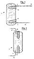
- a proportional and selective heating boiler comprises a reservoir 1 in which sanitary water to be heated is supplied, coming from a water network, through an inlet 2 and a duct 15.
- the water that enters reservoir 1 has an inlet flow oriented towards the bottom of reservoir 1 same.
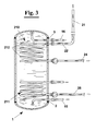
- the sanitary water is heated in reservoir 1, by at least a first and a second heating means, for example a couple of electrical resistances 10 and 11 (figures 1 and 2), or alternatively, by means of two coil tubes 210 and 211 in which a heating fluid flows, for example water (figure 3).
- the water is, moreover, drawn off reservoir 1 at the desired temperature from an outlet 3 and a duct 16 connected to different deliveries, not shown.
- second heating means 10, or 210 is located in the upper portion of reservoir 1, and precisely near water outlet 3.
- First heating means 11, or 211 is arranged in the lower part of the cylindrical portion of the reservoir near water inlet 2.
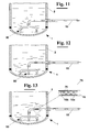
- inlet 2 and outlet 3 of the sanitary water can be arranged at the bottom and at the top of reservoir 1 (figure 2).
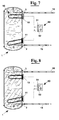
- FIG 4 an exemplary embodiment is shown alternative to the previous where a third heating means, for example a resistance 12, is arranged between the upper heating means 10 and the lower heating means 11.
- This solution can be provided, for example, in case of large reservoirs or for heating much more water at the upper part of reservoir 1.
- the third heating means can be a coil tube 212 arranged connected hydraulically to coil tubes 210 and 211 in order to obtain a resulting coil tube 215 that crosses reservoir 1 for all its length.
- the water is heated by a solar panel 20 whereas in the case shown in figure 6 the heating fluid receives the heat necessary to raise the water temperature of reservoir 1 by an electrical resistance or by a stove 30 supplied with gas or diesel oil.
- the central portion 212 of the resulting coil tube 215 has less coils than the two extreme portions 210 and 211. More in detail, at the two extreme portions 210 and 211 where the coils are enough dense an higher amount of heat is exchanged, whereas at a central portion 212 where the coils are less, a smaller amount of heat is exchanged.
- the exchange in the lower zone of reservoir 1 generates, as well known, convection flow that keep the cold water towards below sending the hot water towards the above, causing the upper part at outlet 3 to have the hottest water. This way hot water at the desired temperature is very quickly available.
- the heating means can be operatively connected to a control board 50.
- a heating means can be singularly operated, for example upper electrical resistance 10 (figure 7) or at the same time both resistances 10 and 11 (figure 8), causing the water of reservoir 1 to be heated quickly, since the two hatched zones of figures 7 and 8 are both heated directly.
- a first solution provides jet spoiling elements 90 arranged at the end of water feeding duct 15 into boiler 1. This arrangement avoids that turbulent flow occurs in the mass of water at the lower part of reservoir 1 and then that hot and cold water mix with each other.
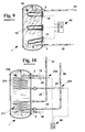
- FIG. 13 Another arrangement of the invention to assure water stratification in reservoir 1 is shown in detail in enlargement 75 of figure 13.
- the water is supplied to reservoir 1 from a duct 15 having a double tube portion.
- inner duct 15a of the double tube portion has a plurality of holes 76 that spoil the water jet entering end portion 15b of duct 15 and then reservoir 1 (figure 13).
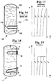
- FIG 14 a further exemplary embodiment is shown for boiler 1.
- duct 16 for drawing water off reservoir 1 and feeding duct 15 are connected by a mixer 80 that mixes the inlet and outlet flows in a predetermined way.
- mixer 80 provides mixing the two flows of water in order to supply the deliveries, not shown, with a resulting water flow 17 at a desired temperature.
- a further exemplary embodiment shown in figure 15 couples boiler 1 to an hydraulic circuit which is arranged for periodically treating with very hot water all the sanitary water circuit.
- the treatment can be carried out for disinfecting the sanitary circuit in order to avoid that bacteria, such as Legionella, moulds or viruses can lie concealed in the boiler and cause the relative pathologies to transfer to people.
- the circulating water must be heated at least at 60°C.
- the boiler 1 is disconnected from the network closing valve 81 on the supply duct. Then, a valve 82 is open arranged along a circulation duct 83 and recirculation of water in boiler 1 activated by a pump 85.
- the treatment temperature for example 65 °C, is chosen through mixer 80.
- figure 19 shows qualitatively the trend of temperature (T) in the mass of water contained in reservoir 1, versus height (h) and time (t). It is observed that boiler 1, according to the invention, provides a certain amount of hot water at the desired temperature T* after a brief time, t 1 . On the contrary water at temperature T* with a boiler 101 of prior art (figure 16) is available only after a time t 4 >>t l (figure 17), since the mass of water contained in the reservoir is heated substantially with uniformity. Figures 17 and 19 are to be intended without that water is drawn off.
- One of the main advantages of the invention is the availability of hot water at the maximum temperature available very quickly, starting from the instant when all the water of the boiler is cold (starting time t 0 ).
Priority Applications (1)
| Application Number | Priority Date | Filing Date | Title |
|---|---|---|---|
| EP07003967A EP1783438A1 (de) | 2002-09-26 | 2003-09-26 | Wasserheizer |
Applications Claiming Priority (4)
| Application Number | Priority Date | Filing Date | Title |
|---|---|---|---|
| ITPI20020053 ITPI20020053A1 (it) | 2002-09-26 | 2002-09-26 | Boiler a riscaldamento proporzionale. |
| ITPI20020053 | 2002-09-26 | ||
| ITPI20020057 ITPI20020057A1 (it) | 2002-10-18 | 2002-10-18 | Boiler a riscaldamento selettivo. |
| ITPI20020057 | 2002-10-18 |
Related Child Applications (1)
| Application Number | Title | Priority Date | Filing Date |
|---|---|---|---|
| EP07003967A Division EP1783438A1 (de) | 2002-09-26 | 2003-09-26 | Wasserheizer |
Publications (2)
| Publication Number | Publication Date |
|---|---|
| EP1403593A2 true EP1403593A2 (de) | 2004-03-31 |
| EP1403593A3 EP1403593A3 (de) | 2004-05-26 |
Family
ID=31980362
Family Applications (2)
| Application Number | Title | Priority Date | Filing Date |
|---|---|---|---|
| EP07003967A Withdrawn EP1783438A1 (de) | 2002-09-26 | 2003-09-26 | Wasserheizer |
| EP03021843A Withdrawn EP1403593A3 (de) | 2002-09-26 | 2003-09-26 | Wasserheizer |
Family Applications Before (1)
| Application Number | Title | Priority Date | Filing Date |
|---|---|---|---|
| EP07003967A Withdrawn EP1783438A1 (de) | 2002-09-26 | 2003-09-26 | Wasserheizer |
Country Status (1)
| Country | Link |
|---|---|
| EP (2) | EP1783438A1 (de) |
Cited By (11)
| Publication number | Priority date | Publication date | Assignee | Title |
|---|---|---|---|---|
| DE102005044845A1 (de) * | 2005-09-20 | 2007-03-22 | Gewofag Gemeinnützige Wohnungsfürsorge AG | Trinkwassererwärmungsanlage |
| FR2891352A1 (fr) * | 2005-09-29 | 2007-03-30 | Clipsol Sa | Commande de la charge d'un ballon electro-solaire. |
| FR2898667A1 (fr) * | 2006-03-15 | 2007-09-21 | Eric Auguste Marcel Lecoq | Chauffe-eau solaire destine a l'elevage des veaux |
| FR2903127A1 (fr) * | 2006-07-03 | 2008-01-04 | Eric Lecoq | Procede de chauffage d'eau pour le nourrissage de veaux. |
| WO2009012853A1 (de) * | 2007-07-24 | 2009-01-29 | Hydro-Energy | Behälter zum speichern eines wärmespeichernden mediums |
| EP2778541A1 (de) * | 2013-03-15 | 2014-09-17 | GEWOFAG Gebäude Service GmbH | Schaltung zur Senkung der primären Rücklauftemperatur in Fernwärmeanlagen |
| US8966929B2 (en) * | 2007-07-20 | 2015-03-03 | General Electric Company | Cooled air recirculation in a refrigerator |
| WO2015107236A1 (es) * | 2014-01-14 | 2015-07-23 | Adolfo Gonzalez Perez | Acumulador energético térmico y aplicaciones |
| WO2016009418A1 (en) * | 2014-07-14 | 2016-01-21 | Keane Bernard Michael | A heating system and a method for controlling a heating system |
| GR20150100154A (el) * | 2015-04-07 | 2016-11-18 | Συστηματα Ηλιακης Και Αιολικης Ενεργειας Φωτοβολταϊκα Θερμανση Ψυξη Αναωνυμος Εταιρεια Με Δ.Τ. Μαλτεζος Αβεε | Θερμοδοχειο ηλιακου θερμοσιφωνα με εναλλακτη ευκαμπτου σωληνα |
| DE102009026420B4 (de) | 2009-05-22 | 2023-10-05 | Joachim Zeeh | Mehrzonen-Schichtladespeicher |
Families Citing this family (1)
| Publication number | Priority date | Publication date | Assignee | Title |
|---|---|---|---|---|
| FR2917816A1 (fr) * | 2007-06-20 | 2008-12-26 | Sun Tec Sarl | Dispositif ameliorant la stratification d'eau chaude dans les chauffe-eau solaires |
Citations (5)
| Publication number | Priority date | Publication date | Assignee | Title |
|---|---|---|---|---|
| US2380545A (en) * | 1943-02-23 | 1945-07-31 | Westinghouse Electric Corp | Water heating apparatus |
| DE2352120A1 (de) * | 1973-10-17 | 1975-04-30 | Bosch Siemens Hausgeraete | Elektrischer heisswasserspeicher |
| US4296799A (en) * | 1979-05-29 | 1981-10-27 | Steele Richard S | Solar water tank and method of making same |
| EP0961082A2 (de) * | 1998-05-29 | 1999-12-01 | Heinz Dötzl | Einrichtung zur Heizung und Warmwasserbereitung |
| US6142216A (en) * | 1994-07-27 | 2000-11-07 | Bradford White Corporation | Indirect water heater |
Family Cites Families (2)
| Publication number | Priority date | Publication date | Assignee | Title |
|---|---|---|---|---|
| EP0173173A3 (de) * | 1984-08-29 | 1986-07-30 | Konvektco Nederland B.V. | Wärmetauscher |
| DK0663569T3 (da) * | 1994-01-14 | 1999-06-21 | Martin Mag Ing Bergmayr | Varmeanlæg, især solvarmeanlæg |
-
2003
- 2003-09-26 EP EP07003967A patent/EP1783438A1/de not_active Withdrawn
- 2003-09-26 EP EP03021843A patent/EP1403593A3/de not_active Withdrawn
Patent Citations (5)
| Publication number | Priority date | Publication date | Assignee | Title |
|---|---|---|---|---|
| US2380545A (en) * | 1943-02-23 | 1945-07-31 | Westinghouse Electric Corp | Water heating apparatus |
| DE2352120A1 (de) * | 1973-10-17 | 1975-04-30 | Bosch Siemens Hausgeraete | Elektrischer heisswasserspeicher |
| US4296799A (en) * | 1979-05-29 | 1981-10-27 | Steele Richard S | Solar water tank and method of making same |
| US6142216A (en) * | 1994-07-27 | 2000-11-07 | Bradford White Corporation | Indirect water heater |
| EP0961082A2 (de) * | 1998-05-29 | 1999-12-01 | Heinz Dötzl | Einrichtung zur Heizung und Warmwasserbereitung |
Cited By (11)
| Publication number | Priority date | Publication date | Assignee | Title |
|---|---|---|---|---|
| DE102005044845A1 (de) * | 2005-09-20 | 2007-03-22 | Gewofag Gemeinnützige Wohnungsfürsorge AG | Trinkwassererwärmungsanlage |
| FR2891352A1 (fr) * | 2005-09-29 | 2007-03-30 | Clipsol Sa | Commande de la charge d'un ballon electro-solaire. |
| FR2898667A1 (fr) * | 2006-03-15 | 2007-09-21 | Eric Auguste Marcel Lecoq | Chauffe-eau solaire destine a l'elevage des veaux |
| FR2903127A1 (fr) * | 2006-07-03 | 2008-01-04 | Eric Lecoq | Procede de chauffage d'eau pour le nourrissage de veaux. |
| US8966929B2 (en) * | 2007-07-20 | 2015-03-03 | General Electric Company | Cooled air recirculation in a refrigerator |
| WO2009012853A1 (de) * | 2007-07-24 | 2009-01-29 | Hydro-Energy | Behälter zum speichern eines wärmespeichernden mediums |
| DE102009026420B4 (de) | 2009-05-22 | 2023-10-05 | Joachim Zeeh | Mehrzonen-Schichtladespeicher |
| EP2778541A1 (de) * | 2013-03-15 | 2014-09-17 | GEWOFAG Gebäude Service GmbH | Schaltung zur Senkung der primären Rücklauftemperatur in Fernwärmeanlagen |
| WO2015107236A1 (es) * | 2014-01-14 | 2015-07-23 | Adolfo Gonzalez Perez | Acumulador energético térmico y aplicaciones |
| WO2016009418A1 (en) * | 2014-07-14 | 2016-01-21 | Keane Bernard Michael | A heating system and a method for controlling a heating system |
| GR20150100154A (el) * | 2015-04-07 | 2016-11-18 | Συστηματα Ηλιακης Και Αιολικης Ενεργειας Φωτοβολταϊκα Θερμανση Ψυξη Αναωνυμος Εταιρεια Με Δ.Τ. Μαλτεζος Αβεε | Θερμοδοχειο ηλιακου θερμοσιφωνα με εναλλακτη ευκαμπτου σωληνα |
Also Published As
| Publication number | Publication date |
|---|---|
| EP1403593A3 (de) | 2004-05-26 |
| EP1783438A1 (de) | 2007-05-09 |
Similar Documents
| Publication | Publication Date | Title |
|---|---|---|
| EP1403593A2 (de) | Wasserheizer | |
| EP3333493B1 (de) | Wasserkreislaufmodul und warmwassersystem mit verwendung davon | |
| US10006663B2 (en) | Device designed to maximize the efficiency and minimize the consumption of both, water and energy, in the utilization of hot water | |
| WO2007059618A1 (en) | Continuous flow demand controlled microwave water heater | |
| CN109210772A (zh) | 一种供热水即开即热板换式壁挂炉 | |
| KR100557803B1 (ko) | 가열장치및그작동방법 | |
| CN201121974Y (zh) | 热水器 | |
| KR100393917B1 (ko) | 열매체유를 이용한 전기보일러 | |
| KR200423080Y1 (ko) | 열매체를 이용한 온수 공급 장치를 구비하는 열매체 보일러 | |
| CN213273198U (zh) | 双出水式电热水器 | |
| WO2004070286A2 (en) | System to heat liquid with electromagnetic energy | |
| KR100926015B1 (ko) | 저탕식 보일러 | |
| CN207065868U (zh) | 一种带有过滤装置的电热水器 | |
| CN111174442A (zh) | 一种分布式热水系统 | |
| CN206055943U (zh) | 快速调温式电热水器 | |
| CN216844880U (zh) | 基于热泵机组的多功能水箱系统 | |
| CN216814345U (zh) | 一种太阳能燃气互补家用热水供应系统 | |
| JP3951173B2 (ja) | 浴室暖房装置 | |
| CN216897449U (zh) | 多机并联供暖供水系统 | |
| JP2006090643A (ja) | 浴室暖房装置 | |
| CN213119537U (zh) | 一种管道连接装置 | |
| KR200176376Y1 (ko) | 가정용 보일러의 온수 예열장치 | |
| CN209165789U (zh) | 一种家用型热水器的高效节能水箱 | |
| CN111076415B (zh) | 一种电热锅炉供热供水系统 | |
| CN208059298U (zh) | 一种带辅助加热器的热泵热水器 |
Legal Events
| Date | Code | Title | Description |
|---|---|---|---|
| PUAI | Public reference made under article 153(3) epc to a published international application that has entered the european phase |
Free format text: ORIGINAL CODE: 0009012 |
|
| AK | Designated contracting states |
Kind code of ref document: A2 Designated state(s): AT BE BG CH CY CZ DE DK EE ES FI FR GB GR HU IE IT LI LU MC NL PT RO SE SI SK TR |
|
| AX | Request for extension of the european patent |
Extension state: AL LT LV MK |
|
| PUAL | Search report despatched |
Free format text: ORIGINAL CODE: 0009013 |
|
| AK | Designated contracting states |
Kind code of ref document: A3 Designated state(s): AT BE BG CH CY CZ DE DK EE ES FI FR GB GR HU IE IT LI LU MC NL PT RO SE SI SK TR |
|
| AX | Request for extension of the european patent |
Extension state: AL LT LV MK |
|
| 17P | Request for examination filed |
Effective date: 20041124 |
|
| AKX | Designation fees paid |
Designated state(s): AT BE BG CH CY CZ DE DK EE ES FI FR GB GR HU IE IT LI LU MC NL PT RO SE SI SK TR |
|
| 17Q | First examination report despatched |
Effective date: 20050719 |
|
| STAA | Information on the status of an ep patent application or granted ep patent |
Free format text: STATUS: THE APPLICATION IS DEEMED TO BE WITHDRAWN |
|
| 18D | Application deemed to be withdrawn |
Effective date: 20070302 |