EP1403450A1 - Verschiebevorrichtung - Google Patents
Verschiebevorrichtung Download PDFInfo
- Publication number
- EP1403450A1 EP1403450A1 EP03015467A EP03015467A EP1403450A1 EP 1403450 A1 EP1403450 A1 EP 1403450A1 EP 03015467 A EP03015467 A EP 03015467A EP 03015467 A EP03015467 A EP 03015467A EP 1403450 A1 EP1403450 A1 EP 1403450A1
- Authority
- EP
- European Patent Office
- Prior art keywords
- piston rod
- guide
- carriage
- support element
- displacement device
- Prior art date
- Legal status (The legal status is an assumption and is not a legal conclusion. Google has not performed a legal analysis and makes no representation as to the accuracy of the status listed.)
- Granted
Links
Images
Classifications
-
- E—FIXED CONSTRUCTIONS
- E21—EARTH OR ROCK DRILLING; MINING
- E21B—EARTH OR ROCK DRILLING; OBTAINING OIL, GAS, WATER, SOLUBLE OR MELTABLE MATERIALS OR A SLURRY OF MINERALS FROM WELLS
- E21B19/00—Handling rods, casings, tubes or the like outside the borehole, e.g. in the derrick; Apparatus for feeding the rods or cables
- E21B19/08—Apparatus for feeding the rods or cables; Apparatus for increasing or decreasing the pressure on the drilling tool; Apparatus for counterbalancing the weight of the rods
- E21B19/086—Apparatus for feeding the rods or cables; Apparatus for increasing or decreasing the pressure on the drilling tool; Apparatus for counterbalancing the weight of the rods with a fluid-actuated cylinder
Definitions
- the invention relates to a displacement device, in particular for construction machines, with a guide, a carriage, which is displaceably mounted on the guide, a control cylinder for moving the carriage, wherein the actuating cylinder has a cylinder housing extendable piston rod, and a support member for securing the piston rod against buckling.
- Displacement devices are used, for example, on construction machines for civil engineering in which, for example, a drill or a vibrator is moved vertically along a vertical mast by the actuating cylinder.
- a construction machine is described for example in DE 198 13 902 C1.
- About the actuating cylinder can be exercised when lowering the drill or vibrator a desired pressure force, which provides the necessary work progress.
- actuating cylinder with a large stroke length of up to 5 m and more are needed. This requires correspondingly long piston rods of the actuating cylinder.
- a slide guide is known to prevent sagging of a horizontally arranged telescopic cylinder.
- a support bearing is frictionally attached to a cylinder tube of the telescopic cylinder.
- the invention has for its object to provide a displacement device in which the risk of buckling a piston rod is reliably counteracted in a simple manner.
- the displacement device according to the invention is characterized in that the support element is displaceably mounted both on the piston rod and on the guide or the carriage, and that the support element is displaceable on extension of the piston rod to a predetermined support position on the piston rod.
- a basic idea of the invention is to provide a displaceable support element on the piston rod which couples the piston rod to the guide or the carriage at a particularly critical position. As a result, the rigidity and thus the security against buckling is increased at the support position. Compared to known displacement devices can be used by the inventive arrangement of the support member with the same or even increased buckling safety a smaller diameter piston rod and thus a cheaper actuator cylinder.
- any type of adjusting cylinders for example a pneumatic cylinder, can be used for the sliding device according to the invention.
- the actuating cylinder is a hydraulic cylinder.
- hydraulic cylinders are used to apply high forces, which lead to a corresponding risk of buckling of the piston rod.
- a preferred embodiment of the displacement device according to the invention is that the actuating cylinder is articulated on the one hand on the guide and on the other hand on the carriage and arranged parallel to the guide. In this arrangement, a good power transmission is achieved by the actuating cylinder on the carriage at the same time good displacement of the support member on the piston rod and the guide or the carriage.
- the support element preferably has slide bushes or sliding shoes, with which the support element is slidably mounted along the piston rod or the guide.
- the support element could be displaceable by means of a slight press fit on the piston rod.
- a particularly low-wear embodiment of the displacement device is inventively achieved in that for moving the support element, a driver is arranged on the carriage. The driver is attached to the carriage so that when reaching the final position of the carriage the slidably mounted support element is guided by the driver up to the desired support position. When retracting the piston rod, the support member can be easily returned by the head of the piston rod together with the carriage in the retracted position.
- a stop on the guide is arranged to limit the displacement of the support element. This is particularly useful when the support element is moved by static friction on the piston rod or by gravity, for example, when the piston rod is extended vertically downwards. A stop ensures a defined position of the support element in the desired support position.
- the support element completely surrounds the piston rod.
- a Gleitbüchse be used, which is mounted on the piston rod.
- the slide bushing is then mounted in a corresponding bearing opening of the support element.
- the support position In the case of a single support element, it is expedient for the support position to be arranged in the center of the extended piston rod when the piston rod is fully extended. Taking into account the corresponding Euler's buckling case, this represents the critical position for the risk of buckling. In this middle position, therefore, the greatest effect against buckling is produced by the supporting element.
- a plurality of support elements are provided on a piston rod, whose respective support position are offset from each other. This can be achieved for example by a cascade-like arrangement of the support elements with correspondingly provided stair-shaped drivers or attacks. In this way, a very long piston rod of over 10 m can be reliably stiffened and supported.
- the displacement device according to the invention can be used in a wide variety of fields. Even with smaller stroke lengths, the invention can be used, wherein it essentially depends on the ratio between the maximum force of the piston rod length, the piston rod diameter and the required buckling safety. Since the initial cost of actuating cylinders increase significantly with increasing size, the use of the displacement device according to the invention is particularly economical especially from stroke lengths of 1 m and more.
- a high efficiency is achieved according to the invention in a construction machine, in which the guide is formed on a vertical mast during operation and the piston rod along the mast downwardly extendable.
- the displacement device is used in particular for rotary drilling rigs for creating foundation piles in the ground.
- the support member may be slidably mounted and moved by gravity into the support position.
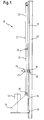
- a displacement device 10 is shown in a partially illustrated drilling device for sinking bores for foundation piles.
- a vertical mast 42 which is commonly associated with a superstructure of a construction vehicle, a trained as a rail guide 12 is arranged.
- a carriage 14 is mounted vertically displaceable over two encompassing sliding devices 15.
- a rotary drive 44 is housed, with which in a known manner a drilling tool, such as a drilling auger, is driven in rotation.
- a positioning cylinder 20 is provided to move the carriage 14 down with a predetermined compressive force. Its cylinder housing 22 is articulated on the mast head, while the extendable in the cylinder housing 22 piston rod 24 is articulated with its head 25 on the carriage 14.
- a plate-shaped support member 16 shown in cross section is slidably mounted via a sliding bushing.
- the support member 16 extends transversely to the piston rod 24 to the guide 12, to which the support member 16 is also slidably mounted via a slide shoe 18.
- the support member 16 remains in the position shown in Figure 1 until a stop surface on the head 25 of the piston rod 24 abuts the support member 16 and this entrains the further retraction of the piston rod 24 and moves up.
- the support element 16 abuts on the one hand on a stop flange 23 of the cylinder housing 22 and on the other hand on the head 25 of the piston rod 24.
- the support member 16 When extending the piston rod 24 with the articulated carriage 14, the support member 16 follows the gravity due to the extension movement until the support member 16 comes in a predetermined support position on a stop 28 on the guide 12 to the plant. The support member 16 remains in this support position until the piston rod 24 has reached with the support member 14 its fully extended position, which is shown in Figure 1. At this maximum stroke length, there is basically the greatest risk of buckling in the middle of the piston rod 24, whereby increased safety is ensured by the positioning of the support elements 16 at this critical point.
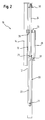
- a further displacement device 10 is explained in connection with a marker device shown in FIG.
- a guide 12 is arranged, along which a mecanicgrukler forming carriage 14 is vertically movable.
- the elongate carriage 14 has in this Switzerlandgrucardi itself a guide rail 13, which ensures a defined linear movement in conjunction with the guide 12.
- a cylinder housing 22 of an actuating cylinder 20 is mounted, which extends parallel to the guide 12 and the guide rail 13, wherein the cylinder housing 22 mounted in the piston rod 24 is connected at its upper end to the head of the carriage 14.
- a support member 16 is slidably mounted both along the piston rod 24 and along the guide rail 13 of the carriage 14.
- the support member 16 In a retracted position of the piston rod 24, the support member 16 rests with its underside on a stop flange 23 of the cylinder housing 22, while the top of the support member 16 is contacted by a stop plate 30 at the top of the piston rod 24.
- the support member 16 When extending the piston rod 24, the support member 16 initially remains in its position on the stop flange 23 until contacted by the piston rod 24 upwardly moving carriage 14 with a driver 26, the underside of the support member 16 and this now moves upwards.
- the driver 26 is arranged on the carriage 14 such that in the maximum extended position of the piston rod 24 the Support member 16 is arranged approximately centrally.
- the definition of the support position is further supported by the fact that a further upward process of the support member 16 prevented by a downwardly directed elongated counter-stop 29, which acts on reaching the support position against a stop 28 on the outer leader.
Landscapes
- Engineering & Computer Science (AREA)
- Geology (AREA)
- Mining & Mineral Resources (AREA)
- Life Sciences & Earth Sciences (AREA)
- General Life Sciences & Earth Sciences (AREA)
- Fluid Mechanics (AREA)
- Mechanical Engineering (AREA)
- Environmental & Geological Engineering (AREA)
- Physics & Mathematics (AREA)
- Geochemistry & Mineralogy (AREA)
- Earth Drilling (AREA)
- Surgical Instruments (AREA)
- Piezo-Electric Or Mechanical Vibrators, Or Delay Or Filter Circuits (AREA)
- Actuator (AREA)
- Forklifts And Lifting Vehicles (AREA)
Abstract
Description
- Die Erfindung betrifft eine Verschiebevorrichtung, insbesondere für Baumaschinen, mit einer Führung, einem Schlitten, welcher an der Führung verschiebbar gelagert ist, einem Stellzylinder zum Verschieben des Schlittens, wobei der Stellzylinder eine aus einem Zylindergehäuse ausfahrbare Kolbenstange aufweist, und einem Stützelement zum Sichern der Kolbenstange gegen Ausknicken.
- Verschiebevorrichtungen kommen beispielsweise an Baumaschinen für den Tiefbau zum Einsatz, bei welchen etwa ein Bohrgerät oder ein Rüttler entlang eines vertikalen Mastes durch den Stellzylinder vertikal verfahren wird. Eine derartige Baumaschine wird beispielsweise in der DE 198 13 902 C1 beschrieben. Über den Stellzylinder kann so beim Niederbringen des Bohrgerätes oder des Rüttlers eine gewünschte Druckkraft ausgeübt werden, welche für den notwendigen Arbeitsfortschritt sorgt. Insbesondere bei diesem Einsatzzweck werden Stellzylinder mit einer großen Hublänge von bis zu 5 m und mehr benötigt. Dies erfordert entsprechend lange Kolbenstangen des Stellzylinders.
- Aufgrund der großen Länge der Kolbenstange sowie der hohen Krafteinwirkung auf die Kolbenstange besteht bei diesen Verschiebevorrichtungen die Gefahr eines Ausknickens der Kolbenstange.
- Um ein Ausknicken der Kolbenstange mit der notwendigen Sicherheit zu verhindern, ist es bekannt, die Kolbenstange mit einem entsprechend großen Querschnitt auszubilden. Dies bedeutet ein entsprechend hohes Gewicht und einen entsprechenden Kostenaufwand für die Stellzylinder.
- Aus der DE 71 46 219 U ist eine Schlittenführung bekannt, die ein Durchhängen eines waagerecht angeordneten Teleskopzylinders verhindern soll. Hierzu ist ein Stützlager an einem Zylinderrohr des Teleskopzylinders kraftschlüssig befestigt.
- In der DE 93 21 598 U1 wird eine Kolbenzylindereinheit mit einem Zylinder und einer Kolbenstange zum Bewegen eines Schildes in einem Behälter offenbart. Sowohl der Zylinder als auch die Kolbenstange weisen dabei eine Lagerstelle auf, die jeweils an einer Arretierschiene arretierbar ist. Durch abwechselndes Arretieren der beiden Lagerstellen und gleichzeitiges Hin- und Herbewegen der Kolbenstange im Zylinder kann eine Mitschreitbewegung der Kolbenzylindereinheit entlang der Arretierschiene erreicht werden.
- Der Erfindung liegt die Aufgabe zugrunde, eine Verschiebevorrichtung anzugeben, bei welcher der Gefahr eines Ausknickens einer Kolbenstange in einfacher Weise zuverlässig entgegengewirkt wird.
- Die Aufgabe wird nach der Erfindung durch eine Verschiebevorrichtung mit den Merkmalen des Anspruchs 1 gelöst. Bevorzugte Ausführungsformen der Erfindung sind in den abhängigen Ansprüchen angegeben.
- Die erfindungsgemäße Verschiebevorrichtung ist dadurch gekennzeichnet, dass das Stützelement sowohl an der Kolbenstange als auch an der Führung oder dem Schlitten verschiebbar gelagert ist, und dass das Stützelement beim Ausfahren der Kolbenstange bis zu einer vorgegebenen Stützposition an der Kolbenstange verschiebbar ist..
- Eine Grundidee der Erfindung liegt darin, an der Kolbenstange ein verschiebbares Stützelement vorzusehen, welches die Kolbenstange an einer besonders kritischen Position mit der Führung oder dem Schlitten koppelt. Hierdurch wird an der Stützposition die Steifigkeit und damit die Sicherheit gegen ein Ausknicken erhöht. Im Vergleich zu bekannten Verschiebevorrichtungen kann durch die erfindungsgemäße Anordnung des Stützelementes bei gleicher oder sogar erhöhter Knicksicherheit eine durchmesserkleinere Kolbenstange und damit ein kostengünstigerer Stellzylinder verwendet werden.
- Grundsätzlich kann für die erfindungsgemäße Verschiebevorrichtung jede Art von Stellzylindern, beispielsweise ein Pneumatikzylinder, eingesetzt werden. Nach der Erfindung ist es aber besonders vorteilhaft, dass der Stellzylinder ein Hydraulikzylinder ist. Denn gerade Hydraulikzylinder dienen zum Aufbringen hoher Kräfte, welche zu einer entsprechenden Gefahr eines Ausknickens der Kolbenstange führen.
- Eine bevorzugte Ausführungsform der erfindungsgemäßen Verschiebevorrichtung besteht darin, dass der Stellzylinder einerseits an der Führung und andererseits an dem Schlitten angelenkt und parallel zur Führung angeordnet ist. Bei dieser Anordnung wird eine gute Kraftübertragung durch den Stellzylinder auf den Schlitten bei gleichzeitig guter Verschiebbarkeit des Stützelementes an der Kolbenstange und der Führung bzw. dem Schlitten erreicht. Das Stützelement weist vorzugsweise Gleitbüchsen oder Gleitschuhe auf, mit welchen das Stützelement entlang der Kolbenstange bzw. der Führung verschiebbar gelagert ist.
- Grundsätzlich könnte das Stützelement über einen leichten Klemmsitz an der Kolbenstange mit dieser verschiebbar sein. Eine besonders verschleißarme Ausführung der Verschiebevorrichtung wird erfindungsgemäß dadurch erreicht, dass zum Verschieben des Stützelementes ein Mitnehmer an den Schlitten angeordnet ist. Der Mitnehmer ist dabei so an dem Schlitten angebracht, dass bei Erreichen der Endposition des Schlittens das gleitend gelagerte Stützelement durch den Mitnehmer bis zu der gewünschten Stützposition geführt ist. Bei Einfahren der Kolbenstange kann das Stützelement in einfacher Weise durch den Kopf der Kolbenstange zusammen mit dem Schlitten in die eingezogene Ausgangsposition rückgeführt werden.
- Nach der Erfindung ist es weiterhin vorteilhaft, dass zum Begrenzen des Verschiebens des Stützelementes ein Anschlag an der Führung angeordnet ist. Dies ist besonders dann sinnvoll, wenn das Stützelement durch Haftreibung an der Kolbenstange oder durch Schwerkrafteinwirkung verfahren wird, beispielsweise wenn die Kolbenstange vertikal nach unten ausgefahren wird. Ein Anschlag sorgt für eine definierte Lage des Stützelementes in der gewünschten Stützposition.
- Für eine besonders gute Versteifung der Kolbenstange ist es erfindungsgemäß vorgesehen, dass das Stützelement die Kolbenstange vollständig umgreift. Hierzu kann beispielsweise eine Gleitbüchse verwendet werden, welche auf die Kolbenstange aufgezogen ist. Die Gleitbüchse ist dann in einer entsprechenden Lageröffnung des Stützelementes befestigt.
- Bei einem einzelnen Stützelement ist es zweckmäßig, dass bei vollständig ausgefahrener Kolbenstange die Stützposition in der Mitte der ausgefahrenen Kolbenstange angeordnet ist. Dies stellt unter Berücksichtigung des entsprechenden Euler' schen Knickfalles die für die Knickgefahr kritische Position dar. In dieser mittleren Position wird also durch das Stützelement die größte Wirkung gegen ein Ausknicken erzeugt.
- Bei besonders großen Hublängen ist es nach der Erfindung vorteilhaft, dass mehrere Stützelemente an einer Kolbenstange vorgesehen sind, deren jeweilige Stützposition zueinander versetzt sind. Dies kann etwa durch eine kaskadenartige Anordnung der Stützelemente mit entsprechend vorgesehenen treppenförmigen Mitnehmern oder Anschlägen erreicht werden. Auf diese Weise kann auch eine sehr lange Kolbenstange von über 10 m zuverlässig versteift und abgestützt werden.
- Grundsätzlich kann die erfindungsgemäße Verschiebevorrichtung in den unterschiedlichsten Gebieten eingesetzt werden. Auch bei kleineren Hublängen kann die Erfindung zum Einsatz kommen, wobei es im Wesentlichen auf das Verhältnis zwischen der maximalen Stellkraft der Kolbenstangenlänge, des Kolbenstangendurchmessers sowie der geforderten Knicksicherheit ankommt. Da die Anschaffungskosten von Stellzylindern mit zunehmender Baugröße erheblich ansteigen, ist der Einsatz der erfindungsgemäßen Verschiebevorrichtung insbesondere ab Hublängen von 1 m und mehr besonders wirtschaftlich.
- Eine hohe Wirtschaftlichkeit wird erfindungsgemäß bei einer Baumaschine erreicht, bei welcher die Führung an einem im Betrieb vertikalen Mast ausgebildet ist und die Kolbenstange entlang des Mastes nach unten ausfahrbar ist. Die Verschiebevorrichtung wird dabei insbesondere für Drehbohrgeräte zum Erstellen von Gründungspfählen im Boden eingesetzt. Das Stützelement kann gleitend gelagert sein und wird durch die Schwerkraft in die Stützposition bewegt.
- Eine weitere vorteilhafte Anwendung ist bei einer Baumaschine gegeben, bei welcher die Führung als ein Innenmäkler und der Schlitten als ein Außenmäkler ausgebildet sind und die Kolbenstange im Betrieb vertikal nach oben ausfahrbar ist. Diese sogenannten Mäklervorrichtungen dienen für sogenannte Rüttler zum Einbringen von Pfählen in lockeren Boden.
- Die Erfindung wird nachfolgend anhand von bevorzugten Ausführungsbespielen erläutert, welche schematisch in den beigefügten Zeichnungen dargestellt sind. In den Zeichnungen zeigen:
- Fig. 1
- eine schematische Seitenansicht einer erfindungsgemäßen Verschiebevorrichtung für ein Bohrgerät; und
- Fig. 2
- eine schematische Seitenansicht einer erfindungsgemäßen Verschiebevorrichtung für einen Mäkler.
- Gemäß Figur 1 ist eine erfindungsgemäße Verschiebevorrichtung 10 in einem teilweise dargestellten Bohrgerät zum Niederbringen von Bohrungen für Gründungspfähle gezeigt. An einem vertikalen Mast 42, welcher üblicherweise mit einem Oberwagen eines Baufahrzeuges in Verbindung steht, ist eine als Schiene ausgebildete Führung 12 angeordnet. Entlang der Führung 12 ist ein Schlitten 14 über zwei umgreifende Gleiteinrichtungen 15 vertikal verschiebbar gelagert. Auf dem Schlitten 14 ist ein Drehantrieb 44 untergebracht, mit welchem in bekannter Weise ein Bohrwerkzeug, wie etwa eine Bohrschnecke, drehend angetrieben wird.
- Zum Verschieben des Schlittens 14 nach unten mit einer vorgegebenen Druckkraft ist ein Stellzylinder 20 vorgesehen. Dessen Zylindergehäuse 22 ist am Mastkopf angelenkt, während die im Zylindergehäuse 22 ausfahrbar gelagerte Kolbenstange 24 mit ihrem Kopf 25 an dem Schlitten 14 angelenkt ist.
- An der zylindrischen Kolbenstange 24 ist ein im Querschnitt dargestelltes plattenförmiges Stützelement 16 über eine Gleitbuchse verschiebbar gelagert. Das Stützelement 16 erstreckt sich quer zur Kolbenstange 24 bis zur Führung 12, an welcher das Stützelement 16 über einen Gleitschuh 18 ebenfalls gleitend verschiebbar gelagert ist. Beim Einfahren der Kolbenstange 24 in das Zylindergehäuse 22 verbleibt das Stützelement 16 in der in Figur 1 dargestellten Lage, bis eine Anschlagsfläche am Kopf 25 der Kolbenstange 24 an dem Stützelement 16 anliegt und dieses beim weiteren Einfahren der Kolbenstange 24 mitnimmt und hoch fährt. In der eingefahrenen Position der Kolbenstange 24 liegt das Stützelement 16 einerseits an einem Anschlagsflansch 23 des Zylindergehäuses 22 und andererseits an dem Kopf 25 der Kolbenstange 24 an.
- Beim Ausfahren der Kolbenstange 24 mit dem angelenkten Schlitten 14 folgt das Stützelement 16 aufgrund seiner Schwerkraft der Ausfahrbewegung, bis das Stützelement 16 in einer vorgegebenen Stützposition an einem Anschlag 28 an der Führung 12 zur Anlage kommt. Das Stützelement 16 verbleibt in dieser Stützposition bis die Kolbenstange 24 mit dem Stützelement 14 ihre vollständig ausgefahrene Position erreicht hat, die in Figur 1 dargestellt ist. Bei dieser maximalen Hublänge besteht grundsätzlich die größte Gefahr des Ausknickens in der Mitte der Kolbenstange 24, wobei durch die Positionierung der Stützelemente 16 an dieser kritischen Stelle eine erhöhte Sicherheit gewährleistet wird.
- Eine weitere erfindungsgemäße Verschiebevorrichtung 10 ist im Zusammenhang mit einer in Figur 2 dargestellten Mäklereinrichtung erläutert. In einem im Betrieb vertikalen Außenmäkler 11 ist eine Führung 12 angeordnet, an welcher entlang ein den Innenmäkler bildenden Schlitten 14 vertikal verfahrbar ist. Der längliche Schlitten 14 weist bei dieser Mäklervorrichtung selbst eine Führungsschiene 13 auf, welche in Verbindung mit der Führung 12 eine definierte lineare Bewegung sicherstellt. Am Außenmäkler 11 ist ein Zylindergehäuse 22 eines Stellzylinders 20 angebracht, welcher sich parallel zur Führung 12 und der Führungsschiene 13 erstreckt, wobei die im Zylindergehäuse 22 gelagerte Kolbenstange 24 an ihrem oberen Ende mit dem Kopf des Schlittens 14 verbunden ist. Ein Stützelement 16 ist sowohl entlang der Kolbenstange 24 als auch entlang der Führungsschiene 13 des Schlittens 14 gleitend verschiebbar gelagert.
- In einer eingefahrenen Position der Kolbenstange 24 liegt das Stützelement 16 mit seiner Unterseite auf einem Anschlagflansch 23 des Zylindergehäuses 22 auf, während die Oberseite des Stützelementes 16 von einer Anschlagplatte 30 am Kopf der Kolbenstange 24 kontaktiert wird.
- Beim Ausfahren der Kolbenstange 24 verbleibt das Stützelement 16 zunächst in seiner Lage auf dem Anschlagflansch 23, bis der durch die Kolbenstange 24 nach oben bewegte Schlitten 14 mit einem Mitnehmer 26 die Unterseite des Stützelements 16 kontaktiert und dieses nunmehr mit nach oben bewegt. Der Mitnehmer 26 ist dabei derart an dem Schlitten 14 angeordnet, dass in der maximal ausgefahrenen Position der Kolbenstange 24 das Stützelement 16 etwa mittig angeordnet ist. Bei dieser Ausführungsform ist die Definierung der Stützposition noch dadurch unterstützt, dass ein weiteres Nachobenverfahren des Stützelements 16 durch einen nach unten gerichteten länglichen Gegenanschlag 29 verhindert, welcher bei Erreichen der Stützposition gegen einen Anschlag 28 an dem Außenmäkler wirkt.
Claims (10)
- Verschiebevorrichtung, insbesondere für Baumaschinen, mit einer Führung (12),
einem Schlitten (14), welcher an der Führung (12) verschiebbar gelagert ist,
einem Stellzylinder (20) zum Verschieben des Schlittens (14), wobei der Stellzylinder (20) eine aus einem Zylindergehäuse (22) ausfahrbare Kolbenstange (24) aufweist, und
einem Stützelement (16) zum Sichern der Kolbenstange (24) gegen Ausknicken,
dadurch gekennzeichnet,
dass das Stützelement (16) sowohl an der Kolbenstange (24) als auch an der Führung (12) oder dem Schlitten (14) verschiebbar gelagert ist, und
dass das Stützelement (16) beim Ausfahren der Kolbenstange (24) bis zu einer vorgegebenen Stützposition an der Kolbenstange (24) verschiebbar ist. - Verschiebevorrichtung nach Anspruch 1,
dadurch gekennzeichnet,
dass der Stellzylinder (20) ein Hydraulikzylinder ist. - Verschiebevorrichtung nach Anspruch 1 oder 2,
dadurch gekennzeichnet,
dass der Stellzylinder (20) einerseits an der Führung (12) und andererseits an dem Schlitten (14) angelenkt und parallel zur Führung (12) angeordnet ist. - Verschiebevorrichtung nach einem der Ansprüche 1 bis 3, dadurch gekennzeichnet,
dass zum Verschieben des Stützelementes (16) ein Mitnehmer (26) an dem Schlitten (14) angeordnet ist. - Verschiebevorrichtung nach einem der Ansprüche 1 bis 4, dadurch gekennzeichnet,
dass zum Begrenzen des Verschiebens des Stützelementes (16) ein Anschlag (28) an der Führung (12) angeordnet ist. - Verschiebevorrichtung nach einem der Ansprüche 1 bis 5, dadurch gekennzeichnet,
dass bei vollständig ausgefahrener Kolbenstange (24) das Stützelement (16) in der Mitte der ausgefahrenen Kolbenstange (24) angeordnet ist. - Verschiebevorrichtung nach einem der Ansprüche 1 bis 6, dadurch gekennzeichnet,
dass das Stützelement (16) die Kolbenstange (24) vollständig umgreift. - Verschiebevorrichtung nach einem der Ansprüche 1 bis 7, dadurch gekennzeichnet,
dass mehrere Stützelemente (16) an einer Kolbenstange (24) vorgesehen sind, deren jeweilige Stützposition zueinander versetzt sind. - Baumaschine mit einer Verschiebevorrichtung nach einem der Ansprüche 1 bis 8,
dadurch gekennzeichnet,
dass die Führung (12) an einem im Betrieb vertikalen Mast (42) ausgebildet ist und
dass die Kolbenstange (24) entlang des Mastes (42) nach unten ausfahrbar ist. - Baumaschine mit einer Verschiebevorrichtung nach einem der Ansprüche 1 bis 8,
dadurch gekennzeichnet,
dass die Führung (12) als ein Innenmäkler und der Schlitten (14) als ein Außenmäkler ausgebildet sind und
dass die Kolbenstange (24) im Betrieb vertikal nach oben ausfahrbar ist.
Applications Claiming Priority (2)
| Application Number | Priority Date | Filing Date | Title |
|---|---|---|---|
| DE10243744 | 2002-09-20 | ||
| DE10243744A DE10243744B4 (de) | 2002-09-20 | 2002-09-20 | Verschiebevorrichtung und Baumaschine mit Verschiebevorrichtung |
Publications (2)
| Publication Number | Publication Date |
|---|---|
| EP1403450A1 true EP1403450A1 (de) | 2004-03-31 |
| EP1403450B1 EP1403450B1 (de) | 2005-04-06 |
Family
ID=31969322
Family Applications (1)
| Application Number | Title | Priority Date | Filing Date |
|---|---|---|---|
| EP03015467A Expired - Lifetime EP1403450B1 (de) | 2002-09-20 | 2003-07-09 | Verschiebevorrichtung |
Country Status (4)
| Country | Link |
|---|---|
| US (1) | US6880453B2 (de) |
| EP (1) | EP1403450B1 (de) |
| AT (1) | ATE292723T1 (de) |
| DE (2) | DE10243744B4 (de) |
Families Citing this family (4)
| Publication number | Priority date | Publication date | Assignee | Title |
|---|---|---|---|---|
| FI20045196A7 (fi) * | 2004-05-31 | 2005-12-22 | Sandvik Tamrock Oy | Teleskooppinen syöttöpalkki kallioporakonetta varten |
| DE102006034890A1 (de) * | 2006-07-25 | 2008-02-07 | Prime Drilling Gmbh | Senkrechtbohranlage |
| WO2011150341A2 (en) | 2010-05-28 | 2011-12-01 | Brasfond Usa Corp. | A pipeline insertion system |
| RU2501931C2 (ru) * | 2011-09-20 | 2013-12-20 | Закрытое акционерное общество "Геомаш-центр" | Устройство для бурения |
Citations (4)
| Publication number | Priority date | Publication date | Assignee | Title |
|---|---|---|---|---|
| DE7146219U (de) | 1973-08-02 | Von Bila Ch | Schlittenführung für Teleskopzylinder | |
| DE2546145A1 (de) * | 1975-10-15 | 1977-04-28 | Ver Flugtechnische Werke | Hoehenverstellbarer geraetetraeger |
| DE19813902C1 (de) | 1998-03-28 | 1999-06-17 | Bauer Spezialtiefbau | Verfahren zum Überwachen einer teleskopierbaren Bohrstange beim Hochziehen ihrer auseinandergezogenen Rohre und Schutzvorrichtung für eine teleskopierbare Bohrstange |
| DE9321598U1 (de) | 1993-05-10 | 2000-04-20 | Max Aicher GmbH Entsorgungstechnik, 83395 Freilassing | Kolbenzylindereinheit, insbesondere zum Bewegen eines Schildes in einem Behälter |
Family Cites Families (4)
| Publication number | Priority date | Publication date | Assignee | Title |
|---|---|---|---|---|
| EP0539752B1 (de) * | 1991-10-31 | 1996-07-31 | Paul Wurth S.A. | Schachtofen-Abstichlochbohrer |
| JP3479754B2 (ja) * | 1995-04-20 | 2003-12-15 | 株式会社フジタ | 岩盤削孔装置 |
| US5988298A (en) * | 1997-03-12 | 1999-11-23 | Ingersoll-Rand Company | Drill rod position stabilizing device |
| CA2338823C (en) * | 2001-02-27 | 2004-07-06 | Hy-Tech Drilling Ltd. | Drilling apparatus |
-
2002
- 2002-09-20 DE DE10243744A patent/DE10243744B4/de not_active Expired - Fee Related
-
2003
- 2003-07-09 EP EP03015467A patent/EP1403450B1/de not_active Expired - Lifetime
- 2003-07-09 AT AT03015467T patent/ATE292723T1/de not_active IP Right Cessation
- 2003-07-09 DE DE50300424T patent/DE50300424D1/de not_active Expired - Lifetime
- 2003-09-22 US US10/665,488 patent/US6880453B2/en not_active Expired - Lifetime
Patent Citations (4)
| Publication number | Priority date | Publication date | Assignee | Title |
|---|---|---|---|---|
| DE7146219U (de) | 1973-08-02 | Von Bila Ch | Schlittenführung für Teleskopzylinder | |
| DE2546145A1 (de) * | 1975-10-15 | 1977-04-28 | Ver Flugtechnische Werke | Hoehenverstellbarer geraetetraeger |
| DE9321598U1 (de) | 1993-05-10 | 2000-04-20 | Max Aicher GmbH Entsorgungstechnik, 83395 Freilassing | Kolbenzylindereinheit, insbesondere zum Bewegen eines Schildes in einem Behälter |
| DE19813902C1 (de) | 1998-03-28 | 1999-06-17 | Bauer Spezialtiefbau | Verfahren zum Überwachen einer teleskopierbaren Bohrstange beim Hochziehen ihrer auseinandergezogenen Rohre und Schutzvorrichtung für eine teleskopierbare Bohrstange |
Also Published As
| Publication number | Publication date |
|---|---|
| EP1403450B1 (de) | 2005-04-06 |
| DE10243744A1 (de) | 2004-04-01 |
| DE50300424D1 (de) | 2005-05-12 |
| DE10243744B4 (de) | 2006-10-12 |
| ATE292723T1 (de) | 2005-04-15 |
| US20040055459A1 (en) | 2004-03-25 |
| US6880453B2 (en) | 2005-04-19 |
Similar Documents
| Publication | Publication Date | Title |
|---|---|---|
| EP2133508B1 (de) | Bauarbeitsgerät mit ausfahrbarem Mast und Verfahren zum Betrieb eines solchen Bauarbeitsgerätes | |
| EP2067924B1 (de) | Bohranlage und Bohrverfahren | |
| EP2161376B1 (de) | Verfahrbarer Fugenschneider | |
| WO1992019837A2 (de) | Erdbohrgerät | |
| DE2108098A1 (de) | Bohrstutze zur mechanischen Ausrich tung und Fuhrung einer Gesteinsbohrmaschine | |
| DE10123403B4 (de) | Bauarbeitsgerät | |
| EP2304179B1 (de) | Automatisiertes bohr- und ankersetzgerät mit separaten lafetten | |
| EP2781682A1 (de) | Kleinbohrgerät | |
| EP1403450B1 (de) | Verschiebevorrichtung | |
| DE2906155A1 (de) | Laengenveraenderbarer support mit gleitfuehrung | |
| EP4279659A1 (de) | Schlitzwandgerät und verfahren zum erstellen eines schlitzes im boden | |
| DE10011994C1 (de) | Seilzugvorrichtung für Berst-/Aufweitvorrichtungen | |
| DE3125082C2 (de) | ||
| EP1795697B1 (de) | Bodenbearbeitungsgerät | |
| CH668453A5 (de) | Ankerbohrvorrichtung. | |
| EP2395153B1 (de) | Verfahren und Vorrichtung zum Herstellen von Wandlamellen im Boden | |
| EP3456914B1 (de) | Doppelkopf-bohrvorrichtung und verfahren zum erstellen einer bohrung | |
| EP0433963B1 (de) | Maschine zum Erweitern eines Stollens, Pilotloches od. dgl. | |
| EP2055664A1 (de) | Translatorisches Stützbein | |
| DE102006062322B3 (de) | Horizontalpressbohranlage | |
| DE10252833B3 (de) | Fräsvorrichtung und Verfahren zur Herstellung eines Schlitzes | |
| EP4112816A1 (de) | Schlitzwandgerät und verfahren zum erstellen eines schlitzes im boden | |
| EP4389984B1 (de) | Mastanordnung für eine baumaschine und verfahren hierzu | |
| DE102023132882B3 (de) | Bohrständer zur Aufnahme, Anordnung und/oder Führung einer Bohrmaschine | |
| DE3011449A1 (de) | Verfahren und vorrichtung zum herstellen eines vertikalen oder geneigten bohrloches |
Legal Events
| Date | Code | Title | Description |
|---|---|---|---|
| PUAI | Public reference made under article 153(3) epc to a published international application that has entered the european phase |
Free format text: ORIGINAL CODE: 0009012 |
|
| AK | Designated contracting states |
Kind code of ref document: A1 Designated state(s): AT BE BG CH CY CZ DE DK EE ES FI FR GB GR HU IE IT LI LU MC NL PT RO SE SI SK TR |
|
| AX | Request for extension of the european patent |
Extension state: AL LT LV MK |
|
| 17P | Request for examination filed |
Effective date: 20040419 |
|
| GRAP | Despatch of communication of intention to grant a patent |
Free format text: ORIGINAL CODE: EPIDOSNIGR1 |
|
| RTI1 | Title (correction) |
Free format text: SHIFTING DEVICE |
|
| AKX | Designation fees paid |
Designated state(s): AT BE BG CH CY CZ DE DK EE ES FI FR GB GR HU IE IT LI LU MC NL PT RO SE SI SK TR |
|
| GRAS | Grant fee paid |
Free format text: ORIGINAL CODE: EPIDOSNIGR3 |
|
| GRAA | (expected) grant |
Free format text: ORIGINAL CODE: 0009210 |
|
| AK | Designated contracting states |
Kind code of ref document: B1 Designated state(s): AT BE BG CH CY CZ DE DK EE ES FI FR GB GR HU IE IT LI LU MC NL PT RO SE SI SK TR |
|
| PG25 | Lapsed in a contracting state [announced via postgrant information from national office to epo] |
Ref country code: IT Free format text: LAPSE BECAUSE OF FAILURE TO SUBMIT A TRANSLATION OF THE DESCRIPTION OR TO PAY THE FEE WITHIN THE PRE;WARNING: LAPSES OF ITALIAN PATENTS WITH EFFECTIVE DATE BEFORE 2007 MAY HAVE OCCURRED AT ANY TIME BEFORE 2007. THE CORRECT EFFECTIVE DATE MAY BE DIFFERENT FROM THE ONE RECORDED.SCRIBED TIME-LIMIT Effective date: 20050406 Ref country code: FI Free format text: LAPSE BECAUSE OF FAILURE TO SUBMIT A TRANSLATION OF THE DESCRIPTION OR TO PAY THE FEE WITHIN THE PRESCRIBED TIME-LIMIT Effective date: 20050406 Ref country code: IE Free format text: LAPSE BECAUSE OF FAILURE TO SUBMIT A TRANSLATION OF THE DESCRIPTION OR TO PAY THE FEE WITHIN THE PRESCRIBED TIME-LIMIT Effective date: 20050406 Ref country code: RO Free format text: LAPSE BECAUSE OF FAILURE TO SUBMIT A TRANSLATION OF THE DESCRIPTION OR TO PAY THE FEE WITHIN THE PRESCRIBED TIME-LIMIT Effective date: 20050406 Ref country code: TR Free format text: LAPSE BECAUSE OF FAILURE TO SUBMIT A TRANSLATION OF THE DESCRIPTION OR TO PAY THE FEE WITHIN THE PRESCRIBED TIME-LIMIT Effective date: 20050406 Ref country code: CZ Free format text: LAPSE BECAUSE OF FAILURE TO SUBMIT A TRANSLATION OF THE DESCRIPTION OR TO PAY THE FEE WITHIN THE PRESCRIBED TIME-LIMIT Effective date: 20050406 Ref country code: SI Free format text: LAPSE BECAUSE OF FAILURE TO SUBMIT A TRANSLATION OF THE DESCRIPTION OR TO PAY THE FEE WITHIN THE PRESCRIBED TIME-LIMIT Effective date: 20050406 Ref country code: SK Free format text: LAPSE BECAUSE OF FAILURE TO SUBMIT A TRANSLATION OF THE DESCRIPTION OR TO PAY THE FEE WITHIN THE PRESCRIBED TIME-LIMIT Effective date: 20050406 Ref country code: EE Free format text: LAPSE BECAUSE OF FAILURE TO SUBMIT A TRANSLATION OF THE DESCRIPTION OR TO PAY THE FEE WITHIN THE PRESCRIBED TIME-LIMIT Effective date: 20050406 Ref country code: NL Free format text: LAPSE BECAUSE OF FAILURE TO SUBMIT A TRANSLATION OF THE DESCRIPTION OR TO PAY THE FEE WITHIN THE PRESCRIBED TIME-LIMIT Effective date: 20050406 Ref country code: GB Free format text: LAPSE BECAUSE OF FAILURE TO SUBMIT A TRANSLATION OF THE DESCRIPTION OR TO PAY THE FEE WITHIN THE PRESCRIBED TIME-LIMIT Effective date: 20050406 |
|
| REG | Reference to a national code |
Ref country code: GB Ref legal event code: FG4D Free format text: NOT ENGLISH |
|
| REG | Reference to a national code |
Ref country code: CH Ref legal event code: EP |
|
| REG | Reference to a national code |
Ref country code: IE Ref legal event code: FG4D Free format text: LANGUAGE OF EP DOCUMENT: GERMAN |
|
| REF | Corresponds to: |
Ref document number: 50300424 Country of ref document: DE Date of ref document: 20050512 Kind code of ref document: P |
|
| REG | Reference to a national code |
Ref country code: DE Ref legal event code: R096 Ref document number: 50300424 Country of ref document: DE Effective date: 20050512 |
|
| PG25 | Lapsed in a contracting state [announced via postgrant information from national office to epo] |
Ref country code: DK Free format text: LAPSE BECAUSE OF FAILURE TO SUBMIT A TRANSLATION OF THE DESCRIPTION OR TO PAY THE FEE WITHIN THE PRESCRIBED TIME-LIMIT Effective date: 20050706 Ref country code: SE Free format text: LAPSE BECAUSE OF FAILURE TO SUBMIT A TRANSLATION OF THE DESCRIPTION OR TO PAY THE FEE WITHIN THE PRESCRIBED TIME-LIMIT Effective date: 20050706 Ref country code: BG Free format text: LAPSE BECAUSE OF FAILURE TO SUBMIT A TRANSLATION OF THE DESCRIPTION OR TO PAY THE FEE WITHIN THE PRESCRIBED TIME-LIMIT Effective date: 20050706 Ref country code: GR Free format text: LAPSE BECAUSE OF FAILURE TO SUBMIT A TRANSLATION OF THE DESCRIPTION OR TO PAY THE FEE WITHIN THE PRESCRIBED TIME-LIMIT Effective date: 20050706 |
|
| PG25 | Lapsed in a contracting state [announced via postgrant information from national office to epo] |
Ref country code: HU Free format text: LAPSE BECAUSE OF FAILURE TO SUBMIT A TRANSLATION OF THE DESCRIPTION OR TO PAY THE FEE WITHIN THE PRESCRIBED TIME-LIMIT Effective date: 20050707 |
|
| PG25 | Lapsed in a contracting state [announced via postgrant information from national office to epo] |
Ref country code: AT Free format text: LAPSE BECAUSE OF NON-PAYMENT OF DUE FEES Effective date: 20050709 Ref country code: LU Free format text: LAPSE BECAUSE OF NON-PAYMENT OF DUE FEES Effective date: 20050709 Ref country code: CY Free format text: LAPSE BECAUSE OF FAILURE TO SUBMIT A TRANSLATION OF THE DESCRIPTION OR TO PAY THE FEE WITHIN THE PRESCRIBED TIME-LIMIT Effective date: 20050709 |
|
| PG25 | Lapsed in a contracting state [announced via postgrant information from national office to epo] |
Ref country code: ES Free format text: LAPSE BECAUSE OF FAILURE TO SUBMIT A TRANSLATION OF THE DESCRIPTION OR TO PAY THE FEE WITHIN THE PRESCRIBED TIME-LIMIT Effective date: 20050717 |
|
| PG25 | Lapsed in a contracting state [announced via postgrant information from national office to epo] |
Ref country code: BE Free format text: LAPSE BECAUSE OF NON-PAYMENT OF DUE FEES Effective date: 20050731 Ref country code: MC Free format text: LAPSE BECAUSE OF NON-PAYMENT OF DUE FEES Effective date: 20050731 |
|
| PG25 | Lapsed in a contracting state [announced via postgrant information from national office to epo] |
Ref country code: PT Free format text: LAPSE BECAUSE OF FAILURE TO SUBMIT A TRANSLATION OF THE DESCRIPTION OR TO PAY THE FEE WITHIN THE PRESCRIBED TIME-LIMIT Effective date: 20050908 |
|
| NLV1 | Nl: lapsed or annulled due to failure to fulfill the requirements of art. 29p and 29m of the patents act | ||
| GBV | Gb: ep patent (uk) treated as always having been void in accordance with gb section 77(7)/1977 [no translation filed] |
Effective date: 20050406 |
|
| REG | Reference to a national code |
Ref country code: IE Ref legal event code: FD4D |
|
| PLBE | No opposition filed within time limit |
Free format text: ORIGINAL CODE: 0009261 |
|
| STAA | Information on the status of an ep patent application or granted ep patent |
Free format text: STATUS: NO OPPOSITION FILED WITHIN TIME LIMIT |
|
| 26N | No opposition filed |
Effective date: 20060110 |
|
| REG | Reference to a national code |
Ref country code: DE Ref legal event code: R097 Ref document number: 50300424 Country of ref document: DE Effective date: 20060109 |
|
| EN | Fr: translation not filed | ||
| BERE | Be: lapsed |
Owner name: BAUER MASCHINEN G.M.B.H. Effective date: 20050731 |
|
| REG | Reference to a national code |
Ref country code: CH Ref legal event code: PL |
|
| PG25 | Lapsed in a contracting state [announced via postgrant information from national office to epo] |
Ref country code: CH Free format text: LAPSE BECAUSE OF NON-PAYMENT OF DUE FEES Effective date: 20070731 Ref country code: LI Free format text: LAPSE BECAUSE OF NON-PAYMENT OF DUE FEES Effective date: 20070731 |
|
| PG25 | Lapsed in a contracting state [announced via postgrant information from national office to epo] |
Ref country code: FR Free format text: LAPSE BECAUSE OF NON-PAYMENT OF DUE FEES Effective date: 20050731 |
|
| PG25 | Lapsed in a contracting state [announced via postgrant information from national office to epo] |
Ref country code: FR Free format text: LAPSE BECAUSE OF NON-PAYMENT OF DUE FEES Effective date: 20050406 |
|
| REG | Reference to a national code |
Ref country code: DE Ref legal event code: R082 Ref document number: 50300424 Country of ref document: DE Representative=s name: WUNDERLICH & HEIM PATENTANWAELTE PARTNERSCHAFT, DE |
|
| PGFP | Annual fee paid to national office [announced via postgrant information from national office to epo] |
Ref country code: DE Payment date: 20220621 Year of fee payment: 20 |
|
| REG | Reference to a national code |
Ref country code: DE Ref legal event code: R071 Ref document number: 50300424 Country of ref document: DE |