EP1403204B1 - Aufzugtürblatt - Google Patents
Aufzugtürblatt Download PDFInfo
- Publication number
- EP1403204B1 EP1403204B1 EP02021993A EP02021993A EP1403204B1 EP 1403204 B1 EP1403204 B1 EP 1403204B1 EP 02021993 A EP02021993 A EP 02021993A EP 02021993 A EP02021993 A EP 02021993A EP 1403204 B1 EP1403204 B1 EP 1403204B1
- Authority
- EP
- European Patent Office
- Prior art keywords
- door leaf
- shells
- shell
- canted
- lift door
- Prior art date
- Legal status (The legal status is an assumption and is not a legal conclusion. Google has not performed a legal analysis and makes no representation as to the accuracy of the status listed.)
- Expired - Lifetime
Links
- 230000000903 blocking effect Effects 0.000 claims description 13
- 239000000463 material Substances 0.000 claims description 7
- 238000003780 insertion Methods 0.000 claims description 4
- 230000037431 insertion Effects 0.000 claims description 4
- 229910052782 aluminium Inorganic materials 0.000 abstract description 2
- XAGFODPZIPBFFR-UHFFFAOYSA-N aluminium Chemical compound [Al] XAGFODPZIPBFFR-UHFFFAOYSA-N 0.000 abstract description 2
- 238000003466 welding Methods 0.000 description 8
- 238000006073 displacement reaction Methods 0.000 description 7
- 238000000034 method Methods 0.000 description 5
- 238000004519 manufacturing process Methods 0.000 description 4
- 229910001220 stainless steel Inorganic materials 0.000 description 4
- 239000010935 stainless steel Substances 0.000 description 4
- 229910000831 Steel Inorganic materials 0.000 description 3
- 238000009434 installation Methods 0.000 description 3
- 229910052751 metal Inorganic materials 0.000 description 3
- 239000002184 metal Substances 0.000 description 3
- 239000010959 steel Substances 0.000 description 3
- 239000000725 suspension Substances 0.000 description 3
- 238000005452 bending Methods 0.000 description 2
- 239000000919 ceramic Substances 0.000 description 2
- 238000004026 adhesive bonding Methods 0.000 description 1
- 239000012790 adhesive layer Substances 0.000 description 1
- 230000015572 biosynthetic process Effects 0.000 description 1
- 238000005253 cladding Methods 0.000 description 1
- 150000001875 compounds Chemical class 0.000 description 1
- 238000013016 damping Methods 0.000 description 1
- 230000001419 dependent effect Effects 0.000 description 1
- 239000010410 layer Substances 0.000 description 1
- 239000007769 metal material Substances 0.000 description 1
- 230000035515 penetration Effects 0.000 description 1
- 238000002360 preparation method Methods 0.000 description 1
Images


Classifications
-
- B—PERFORMING OPERATIONS; TRANSPORTING
- B66—HOISTING; LIFTING; HAULING
- B66B—ELEVATORS; ESCALATORS OR MOVING WALKWAYS
- B66B13/00—Doors, gates, or other apparatus controlling access to, or exit from, cages or lift well landings
- B66B13/30—Constructional features of doors or gates
- B66B13/303—Details of door panels
Definitions
- the present invention relates to a double-shell elevator door leaf according to the preamble of claim 1.
- door leaves for elevators double-shelled.
- elevator door leaves or Fahrschachttissue which are for elevator shafts provided with fire protection class F90 according to DIN 18091 are pointed out.
- the two shells of a double-shelled Door leaf which are usually formed as sheets are usually welded at their edges by welding connected with each other. This is done Welding typically in the form of long seams or correspondingly dimensioned rows of dots. Instead of through Welding can also make the connection at the edges by riveting, Screwing or gluing done.
- From EP 1 083 290 A1 is a double-shell elevator door leaf known.
- This elevator door leaf has a front wall and a rear wall connected to each other by connecting means are connected, the heat-releasable are, in addition, at least one heat-resistant compound is provided.
- JP 5058574 is a single-shell ceramic panel for Use with a lift known, being on a sheet metal wall a three-layer ceramic cladding is glued firmly with the help of an adhesive layer.
- the invention seeks to bivalve door leaves for elevators to provide in a cost effective manner, and in particular to simplify the production of such door leaves.
- the two shells of a doppelschaligen elevator door leaf on their long sides or Longitudinal edges form fit to connect with each other. According to the invention thus omitted on the long sides of the shells or the elevator door leaf the hitherto necessary welding process. Elevator door leaves according to the invention are thus opposite conventional elevator door leaves in much simpler and cheaper way to produce and assemble.
- first and the second Shell at its upper and / or lower ends by means of Screw connections are interconnected.
- This Measure eliminates the conventional in the production of Elevator door leaves used welding process completely.
- elevator door leaves floor-level with a stainless steel sheet to dress however, for the load-bearing door leaf to use a simple sheet steel.
- the connecting of stainless steel sheets and steel sheets is relative consuming, whereby the production costs for such trained elevator doors is high. This is something like that manufactured door leaf also heavier than a door leaf with only one sheet for each shell.
- This effort can according to the invention be avoided, as well as shells of different Material easily connected together can be.
- Elevator door leaf are the first and second Shells forming the double-shell elevator door leaf, longitudinally with form-fitting in operative connection formed movable curbs.
- Such folds are in a simple manner on steel sheets or stainless steel sheets be formed and dimensioned so that they with appropriate Southschieben the two shells ensure a positive connection of these shells can.
- the folds of the first and / or the second Shell with respect to its respective door leaf surface or Main extension plane (i.e., the elevator door surfaces) to one Side trained.
- Main extension plane i.e., the elevator door surfaces
- This ensures that the folds the first shell the corresponding folds of the second shell on both sides or vice versa.
- the two shells can be in the longitudinal direction of the door leaf to achieve a positive connection with each other be pushed.
- the Umkantungen a shell to opposite sides of the each door leaf surface formed. This is achieved that on the first longitudinal side, the fold of the first shell comprises the fold of the second shell, and on the second long side, the fold-over of the second shell includes the fold of the first shell, or vice versa.
- the fold of the first shell comprises the fold of the second shell
- the fold-over of the second shell includes the fold of the first shell, or vice versa.
- Elevator door leaf include or define the folded edges of at least one shell on at least one Long side of a labyrinth process.
- Labyrinth extensions which are known per se, are used for fire protection and prevent the penetration of flames between the door leaves or between the door leaves and the door frames.
- Such labyrinth processes can be, in particular in one piece, on the inventively proposed, longitudinal side form extending Umkantungen.
- first and the second Shell are longitudinally and / or transversely collapsible.
- Elevator door leaf are the two shells of different Materials produced.
- the attachment is such made of different materials Shells in a particularly simple manner possible.
- the shells are at their upper and lower respectively Ends with apertured areas formed, the screw connections in these breakthroughs can be introduced. With this measure it is in particular easily possible, by means of a single Screw the two shells and a corresponding Door leaf guide to fasten together.
- the folded edges with respect to the respective door leaf surfaces differently angled areas exhibit.
- suitable angle selection of the respective Umkantungs Schemee can form-fitting and / or non-positive Installations of the respective folds together be set as desired, which in particular Rattling noises are avoidable.
- the respective outer regions define the Umbantungen oblique Einschiebe Suitee, which the lateral telescoping of the shells strong is simplified. Subsequently to such Einschiebe Suitee can form oblique or angled blocking areas its the side re-collapsing prevent. Such insertion and / or blocking areas preferably have an angle of about 5 to 15 ° with respect the door leaf surfaces on.
- the end region with the inner Edges from the door leaf surface with one after inside led 90 ° -Kantung begins, to which after a straight piece, which in its length the space between defined the shells, an outwardly directed 180 ° -Kantung followed.
- Elevator door leaves include the folds of the first shell on both longitudinal sides of the folds of the second shell. With this measure is a particularly simple Realization of the double-shelled invention Elevator door leaf provided.
- At least one shell has an outer folded edge, which designed as guided in the direction of the door leaf U-profile is in which the respective inner fold of the other Shell is held. This prevents the respective last or outer Umkantungsab songs the outer U-profile by its length a lateral displacement of the Bowls to each other.
- Einschiebe- or Blocking realized in a particularly simple manner.
- FIG 1 In Figure 1 can be seen two door shells 10, 20, which for Formation of a double-shell elevator door leaf 30, like it is shown in Figure 2, laterally collapse are.
- the shells 10, 20 each have a door leaf surface 10a or 20a, which defines both sides of the door leaf become.
- the door leaf surface 10 a of the shell 10 is closed by a first folded edge 12 and a second folded edge 14 at.
- the first fold 12 has a to the door leaf surface 10a subsequent, with respect to this vertically extending Section 12a, in turn perpendicular to the Section 12a and thus parallel to the door leaf surface 10a extending section 12b, and join the section 12b subsequent, a bevel having End section 12c on.
- Section 12c is with respect to formed of section 12b bent substantially by 180 °, so that it is essentially parallel to the section 12b and the door leaf surface 10a extends.
- the end section 12 has a first, substantially parallel to the door leaf surface extending portion 12c ', and an adjoining blocking region 12c ", the is designed here as a blocking bevel, on.
- the blocking slope runs slightly obliquely with respect to the area 12c 'and the Tüblatt Chemistry 10a.
- the bending area or the edge between sections 12b and 12c and hereby in particular the area of the bend facing the door leaf is referred to as Einschiebe Society 12d.
- the blocking region 12c not in the form of a Inclined, but by means of a corresponding material or sheet thickness to realize.
- the second folded edge 14 of the first shell 10 has a first section 14a, which is in the same Direction as section 12a perpendicular to the door leaf surface 10a, one subsequent to the portion 14a Section 14b, which with respect to the section 14a um 180 ° bent, and an end portion 14c on.
- the section 14c is about 90 ° with respect to the portion 14b bent.
- the 90 ° edge between the door leaf surface 10a and the section 14a is designated 14f, the 180 ° edge between sections 14a and 14b with 14e.
- the second shell 20 has corresponding, to the door leaf surface 20a subsequent folds 22, 24 on. These Bends 22, 24 are accordingly with sections or Edges 22a, 22b, 22c, 22d and 24a, 24b, 24c, 24e, 24f formed.
- the sections 12c, 22c represent the blocking areas against a lateral breakup, which with respect to the door leaf surfaces 10a, 20a at an angle of preferably 5 to 15 ° degrees.
- the folded edges 12, 14, 22, 24 extend substantially over the entire longitudinal sides of the respective shells 10, 20, but wherein the folded edges 14, 24 and recesses can have.
- the Umkantungsabête 14a and 24a will be the thickness of the intended door leaf specified.
- a stiffening element 28 for example, a honeycomb carton or an aluminum grid, brought in.
- This stiffening part can, for example before pushing the shells 10, 20 together on one of Shells are fixed. It would also be possible to have several Stiffening elements 28 after pushing the shells together 10, 20 with appropriate design of the areas 15, 27, 21 between the shells to bring. As preferred Possibility of fixing is pointed to a bond.
- a stiffening element 28 can the stability of elevator door leaves and in particular the noise damping of the door leaf surfaces themselves sustainable be improved.
- connection or attachment of the shells 10, 20 together was by means of a relative displacement realized this shells in the door leaf transverse direction.
- the illustrated connection or attachment of the shells 10, 20 together was by means of a relative displacement realized this shells in the door leaf transverse direction.
- the figures 1 and 2 shown Umkantungen leave also a connection of the shells 10, 20 to each other by means of a displacement in the door leaf longitudinal direction, i.e. in the illustration of Figure 2 by means of a shift the shells perpendicular to the plane of the drawing.
- This fold 15 consists of a one-piece surface area formed on the door leaf surface 10a, the running as a transverse to the door leaf longitudinal fold 15 is formed with the sections 15a and 15b.
- the area 15 is shorter in the door width direction the distance between the surfaces 12a and 14a, resulting in the entire area 15 with its sections 15a and 15b at the edge between the surfaces 12a and 14a in FIG push the interior of the door leaf.
- a section 13 which is in the same Direction as Section 12a extends, but narrower is formed and the upper portion of the shell 10 also rigidly designed.
- the door leaf surface 10a is in its upper portion formed with a recess 41.
- a folded edge 27 is provided, which is formed with an opening 29.
- the folded edge 27 extends substantially vertically to the door leaf surface 20a, and is as a one-piece extension formed by this.
- the fold 27 and the breakthrough 29 can also be seen in FIG.
- extension 21 with its sections 21 a and 21b and the folded edge 27 shorter in Schollraum as the distance between the surfaces 12a and 14a and fit as well as the Umkantungen 15 in the interior of the door leaf.
- the shells 10, 20 are in the same view as in Figure 3, but in sixteengeschobenem or with each other connected state shown.
- the breakthrough 41, 42 thus provided can be used for attachment a fastener for a door leaf suspension or a carriage 58 may be used. Especially can the breakthrough 41, 42 for attaching a screw 60 are used, which both for attachment the shells 10, 20 together, as well as for fastening the Door leaf suspension 58 is used on the trays.
- FIG 4 can be seen further that in the aligned openings 17, 29 of the folded portions 15 b and 27 a Screw fastening is introduced.
- the screw fastening is designated overall by 50 and has a screw 51st and a nut 52.
- a lower guide 54 with a Sliding surface 56 of the elevator door leaf with the shells 10, 20 connected is.
- the Screw 50 are thus the shells 10, 20 in their lower area to each other as well screwed to the lower door leaf guide 54.
- the Lower door leaf guide 54 is thus on the bends 15b, 27 of the respective shells fastened to the door leaf.
- the door leaf shown modular and no welding is necessary, preferably, the one facing the user Shell 10 made of another metallic material or even made of a plastic than the back, Shaft-side shell 20. According to the invention is thus a subsequent disguises no longer necessary, causing Overall, a significant weight saving can be achieved can.
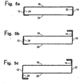
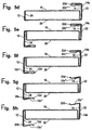
- Figure 5 the view of Figures 1 to 3 corresponding horizontal sectional views various preferred embodiments of the invention double-shelled door leaf.
- the respective shells 10th or 20 are the respective shells 10th or 20.
Landscapes
- Elevator Door Apparatuses (AREA)
- Securing Of Glass Panes Or The Like (AREA)
Description
- Figur 1
- in einem horizontalen Schnitt eine erste bevorzugte Ausführungsform zweier Schalen eines doppelschaligen Aufzugtürblattes vor ihrem seitlichen Ineinanderschieben,
- Figur 2
- in der Ansicht der Figur 1 die Schalen in zusammengeschobener Position,
- Figur 3
- in einer senkrechten Schnittansicht, die ersten und zweiten Schalen gemäß den Figuren 1 und 2 vor ihrer Befestigung aneinander,
- Figur 4
- in der gleichen Ansicht wie Figur 3 die zu einem doppelschaligen Türblatt miteinander verbundenen Schalen, und
- Figur 5
- in horizontaler Schnittansicht weitere bevorzugte Ausführungsformen eines erfindungsgemäßen doppelschaligen Aufzugtürblattes in schematischer Darstellung.
Claims (17)
- Doppelschaliges Aufzugtürblatt mit einer ersten Türschale (10) und einer zweiten Türschale (20), die in ihrer Fläche einen Abstand voneinander aufweisen,
dadurch gekennzeichnet, dass die erste und die zweite Schale (10, 20) an ihren Längsseiten Umkantungen aufweisen in der Art, dass die Umkantungen der ersten und der zweiten Schale (10, 20) einander formschlüssig umgreifen, wobei an jeder Längsseite die Umkantungen jeweils einer der beiden Schalen (10, 20) die Umkantungen der jeweils anderen der beiden Schalen (20, 10) umgreifen, und dass die Schalen (10, 20) im zu dem Türblatt zusammengefügten Zustand durch die Umkantungen in seitlicher Richtung gegen ein Auseinanderfallen blockiert sind. - Aufzugtürblatt nach Anspruch 1, dadurch gekennzeichnet, dass die erste und die zweite Schale (10, 20) an ihren oberen und/oder unteren Enden mittels Schraubverbindungen miteinander verbunden sind.
- Aufzugtürblatt nach Anspruch 1 oder 2, dadurch gekennzeichnet, dass die Umkantungen (12, 14, 22, 24) der Schalen (10, 20) derart ausgebildet sind, dass auf der ersten Längsseite die Umkantung (12) der ersten Schale (10) die Umkantung (24) der zweiten Schale umfasst, und auf der zweiten Längsseite die Umkantung (22) der zweiten Schale (20) die Umkantung (14) der ersten Schale (10) umfasst, oder umgekehrt.
- Aufzugtürblatt nach einem der vorstehenden Ansprüche, dadurch gekennzeichnet, dass die Umkantungen der ersten und/oder der zweiten Schale (10, 20) bezüglich der jeweiligen Türblattfläche (10a, 20a) der Schalen (10, 20) zu einer Seite hin ausgebildet sind.
- Aufzugtürblatt nach einem der vorstehenden Ansprüche, dadurch gekennzeichnet, dass die Umkantungen der ersten und/oder der zweiten Schale (10, 20) bezüglich der jeweiligen Türblattfläche (10a, 20a) der Schalen zu entgegengesetzten Seiten hin ausgebildet sind.
- Aufzugtürblatt nach einem der vorstehenden Ansprüche, dadurch gekennzeichnet, dass die Umkantungen (12, 14, 22, 24) wenigstens an einer Längsseite im Wesentlichen die Dicke des Türblattes definieren.
- Aufzugtürblatt nach einem der vorstehenden Ansprüche, dadurch gekennzeichnet, dass die Umkantungen (12, 14, 22, 24) wenigstens einer Schale (10, 20) an wenigstens einer Längsseite einen Labyrinthfortsatz umfassen bzw. definieren.
- Aufzugtürblatt nach einem der vorstehenden Ansprüche 2 bis 7, dadurch gekennzeichnet, dass die Schraubverbindungen zur Befestigung der oberen und/oder der unteren Enden der Schalen (10, 20) aneinander gleichzeitig zur Befestigung von oberen und/oder unteren Türführungen (54, 56) an den oberen und/oder unteren Enden des Aufzugtürblattes dienen.
- Aufzugtürblatt nach einem der vorstehenden Ansprüche, dadurch gekennzeichnet, dass die erste und zweite Schale an ihren Längsseiten kraftschlüssig miteinander verbunden sind.
- Aufzugtürblatt nach einem der vorstehenden Ansprüche, dadurch gekennzeichnet, dass die erste und die zweite Schale (10, 20) längs und/oder quer zusammenschiebbar sind.
- Aufzugtürblatt nach einem der vorstehenden Ansprüche, dadurch gekennzeichnet, dass die beiden Schalen (10, 20) aus unterschiedlichen Werkstoffen hergestellt sind.
- Aufzugtürblatt nach einem der vorstehenden Ansprüche, dadurch gekennzeichnet, dass bei beiden Schalen (10, 20) die Bereiche zur Anordnung der Türführungen in den oberen und unteren Endbereichen der Türblattflächen (10a, 20a) als sich einteilig an die Türblattflächen (10a, 20a) anschließende Flächenbereiche (13, 15b, 21, 27) mit Durchbrüchen (41, 17, 42, 29) ausgebildet sind.
- Aufzugtürblatt nach einem der vorstehenden Ansprüche, dadurch gekennzeichnet, dass insbesondere die jeweils inneren Umkantungen (14, 24) ausgehend von der jeweiligen Türblattfläche (10a, 20a) zunächst eine 90°-Kantung (14f, 24f) aufweisen, an die sich ein senkrecht zu der jeweiligen Türblattfläche verlaufendes, gerades Stück (14a, 24a) anschließt, dass in seiner Länge dem Freiraum zwischen den Schalen (10, 20) bzw. der Türblattdicke entspricht, wobei sich an dieses gerade Stück (14a, 24a) eine nach außen geführte 180°-Kantung (14e, 24e) anschließt.
- Aufzugtürblatt nach Anspruch 13, dadurch gekennzeichnet, dass der freie Schenkel der 180°-Kantung an seinem Ende eine weitere im wesentlichen 90°-Kantung wieder zurück in Richtung Türblatt aufweist, wobei der freie Schenkel einen Einschiebe- bzw. Blockierbereich bildet.
- Aufzugtürblatt nach einem der vorstehenden Ansprüche, dadurch gekennzeichnet, dass die jeweils äußeren Umkantungsbereiche Einschiebebereiche (12d, 22d) und Blockierbereiche (12c", 22c") enthalten.
- Aufzugtürblatt nach einem der Ansprüche 1, 2, 6, 8, 10, 11, 12 oder 15, dadurch gekennzeichnet, dass die Umkantungen der ersten Schale (10) an beiden Längsseiten die Umkantungen der zweiten Schale (20) umfassen.
- Aufzugtürblatt nach einem der vorstehenden Ansprüche 1, 2, 6, 8, 10, 11, 12, 15 oder 16, dadurch gekennzeichnet, dass wenigstens eine Schale (10, 20) eine äußere Umkantung aufweist, welche als in Richtung des Türblattes geführtes U-Profil ausgebildet ist, in dem die jeweils innere Umkantung der anderen Schale (20, 10) gehalten ist.
Priority Applications (5)
| Application Number | Priority Date | Filing Date | Title |
|---|---|---|---|
| DE50203153T DE50203153D1 (de) | 2002-09-30 | 2002-09-30 | Aufzugtürblatt |
| ES02021993T ES2241939T3 (es) | 2002-09-30 | 2002-09-30 | Hoja de puerta de ascensor. |
| PT02021993T PT1403204E (pt) | 2002-09-30 | 2002-09-30 | Folha de porta de elevador |
| EP02021993A EP1403204B1 (de) | 2002-09-30 | 2002-09-30 | Aufzugtürblatt |
| AT02021993T ATE295825T1 (de) | 2002-09-30 | 2002-09-30 | Aufzugtürblatt |
Applications Claiming Priority (1)
| Application Number | Priority Date | Filing Date | Title |
|---|---|---|---|
| EP02021993A EP1403204B1 (de) | 2002-09-30 | 2002-09-30 | Aufzugtürblatt |
Publications (2)
| Publication Number | Publication Date |
|---|---|
| EP1403204A1 EP1403204A1 (de) | 2004-03-31 |
| EP1403204B1 true EP1403204B1 (de) | 2005-05-18 |
Family
ID=31970350
Family Applications (1)
| Application Number | Title | Priority Date | Filing Date |
|---|---|---|---|
| EP02021993A Expired - Lifetime EP1403204B1 (de) | 2002-09-30 | 2002-09-30 | Aufzugtürblatt |
Country Status (5)
| Country | Link |
|---|---|
| EP (1) | EP1403204B1 (de) |
| AT (1) | ATE295825T1 (de) |
| DE (1) | DE50203153D1 (de) |
| ES (1) | ES2241939T3 (de) |
| PT (1) | PT1403204E (de) |
Cited By (1)
| Publication number | Priority date | Publication date | Assignee | Title |
|---|---|---|---|---|
| CN101850926A (zh) * | 2009-04-06 | 2010-10-06 | 三菱电机株式会社 | 电梯的门装置 |
Families Citing this family (4)
| Publication number | Priority date | Publication date | Assignee | Title |
|---|---|---|---|---|
| ATE496858T1 (de) | 2007-05-29 | 2011-02-15 | Thyssenkrupp Aufzugswerke Gmbh | Aufzugstürblatt |
| ITMI20080734A1 (it) | 2008-04-23 | 2009-10-24 | Prisma S R L | Kit monoblocco per ascensore |
| ES2651725B1 (es) * | 2016-07-27 | 2018-10-17 | Juan Ramón GOMIS RABASSA | Hoja de puerta de ascensor y procedimiento para su fabricación |
| ES2989023T3 (es) | 2021-09-07 | 2024-11-25 | Wittur Holding Gmbh | Panel de base de chapa metálica para su uso en ascensores |
Family Cites Families (4)
| Publication number | Priority date | Publication date | Assignee | Title |
|---|---|---|---|---|
| JP2857513B2 (ja) * | 1991-08-29 | 1999-02-17 | 株式会社日立ビルシステム | エレベータの扉 |
| FR2720383B1 (fr) * | 1994-05-24 | 1996-07-12 | Realisations Metallurg | Porte d'ascenseur et son procédé de montage. |
| DE19645517A1 (de) * | 1996-10-25 | 1998-04-30 | Haushahn C Gmbh Co | Türblatt, insbesondere für Aufzugstüren |
| DK1083290T3 (da) * | 1999-09-08 | 2005-06-27 | Inventio Ag | Elevatordörplade |
-
2002
- 2002-09-30 ES ES02021993T patent/ES2241939T3/es not_active Expired - Lifetime
- 2002-09-30 EP EP02021993A patent/EP1403204B1/de not_active Expired - Lifetime
- 2002-09-30 DE DE50203153T patent/DE50203153D1/de not_active Expired - Lifetime
- 2002-09-30 PT PT02021993T patent/PT1403204E/pt unknown
- 2002-09-30 AT AT02021993T patent/ATE295825T1/de active
Cited By (1)
| Publication number | Priority date | Publication date | Assignee | Title |
|---|---|---|---|---|
| CN101850926A (zh) * | 2009-04-06 | 2010-10-06 | 三菱电机株式会社 | 电梯的门装置 |
Also Published As
| Publication number | Publication date |
|---|---|
| ATE295825T1 (de) | 2005-06-15 |
| DE50203153D1 (de) | 2005-06-23 |
| EP1403204A1 (de) | 2004-03-31 |
| PT1403204E (pt) | 2005-09-30 |
| ES2241939T3 (es) | 2005-11-01 |
Similar Documents
| Publication | Publication Date | Title |
|---|---|---|
| EP2976250B1 (de) | Schweller für eine fahrzeugkarosserie | |
| EP0887235B1 (de) | Strukturbauteil für Fahrzeuge | |
| DE10108287B4 (de) | Karosseriestruktur | |
| DE10206768B4 (de) | Kotflügelanordnung für ein Kraftfahrzeug | |
| EP2773549B1 (de) | Hilfsrahmen mit sicken | |
| EP2606766B1 (de) | Ausziehführung für Schubkästen mit einem Fanghaken | |
| EP2014539B1 (de) | Kraftfahrzeugkarosserie mit seitlichen Schwellern | |
| DE102005029738A1 (de) | Energieabsorberelement und dieses verwendende Kraftfahrzeugkarosserie | |
| DE102008045914A1 (de) | Rohranordnung sowie Querträger mit einer solchen Rohranordnung | |
| DE69323638T2 (de) | Aufbau eines Wagenkastens | |
| EP1995156A1 (de) | Tragstruktur eines Kraftfahrzeugs | |
| DE102014211086B4 (de) | Fahrzeugfrontstruktur | |
| DE2501611B2 (de) | Flanschverbindung für rechteckige Klimatisierungskanäle | |
| AT518076B1 (de) | Schubladenseitenwand | |
| DE60203443T2 (de) | Oberste Fahrzeugkarrosseriestruktur | |
| EP2003280B1 (de) | Türblatt, vorzugsweise für eine Hauseingangstür. | |
| EP0312646B1 (de) | Mittelträger für Fensterrahmen | |
| DE19901070C1 (de) | Befestigungsanordnung eines Türschwellers am Bodenblech eines Kraftwagens | |
| EP2206450A1 (de) | Schiene zum Aufhängen von Schränken | |
| EP3442816B1 (de) | Rahmensystem | |
| DE102009021964A1 (de) | Hohlprofil für eine Fahrzeugkarosserie | |
| EP1403204A1 (de) | Aufzugtürblatt | |
| DE19645517A1 (de) | Türblatt, insbesondere für Aufzugstüren | |
| DE102013201437B4 (de) | Kraftfahrzeug | |
| EP3290603A1 (de) | Entwässerungsrinne |
Legal Events
| Date | Code | Title | Description |
|---|---|---|---|
| PUAI | Public reference made under article 153(3) epc to a published international application that has entered the european phase |
Free format text: ORIGINAL CODE: 0009012 |
|
| 17P | Request for examination filed |
Effective date: 20030425 |
|
| AK | Designated contracting states |
Kind code of ref document: A1 Designated state(s): AT BE BG CH CY CZ DE DK EE ES FI FR GB GR IE IT LI LU MC NL PT SE SK TR |
|
| AX | Request for extension of the european patent |
Extension state: AL LT LV MK RO SI |
|
| GRAP | Despatch of communication of intention to grant a patent |
Free format text: ORIGINAL CODE: EPIDOSNIGR1 |
|
| AKX | Designation fees paid |
Designated state(s): AT BE BG CH CY CZ DE DK EE ES FI FR GB GR IE IT LI LU MC NL PT SE SK TR |
|
| GRAS | Grant fee paid |
Free format text: ORIGINAL CODE: EPIDOSNIGR3 |
|
| GRAA | (expected) grant |
Free format text: ORIGINAL CODE: 0009210 |
|
| AK | Designated contracting states |
Kind code of ref document: B1 Designated state(s): AT BE BG CH CY CZ DE DK EE ES FI FR GB GR IE IT LI LU MC NL PT SE SK TR |
|
| PG25 | Lapsed in a contracting state [announced via postgrant information from national office to epo] |
Ref country code: SK Free format text: LAPSE BECAUSE OF FAILURE TO SUBMIT A TRANSLATION OF THE DESCRIPTION OR TO PAY THE FEE WITHIN THE PRESCRIBED TIME-LIMIT Effective date: 20050518 Ref country code: EE Free format text: LAPSE BECAUSE OF FAILURE TO SUBMIT A TRANSLATION OF THE DESCRIPTION OR TO PAY THE FEE WITHIN THE PRESCRIBED TIME-LIMIT Effective date: 20050518 Ref country code: FI Free format text: LAPSE BECAUSE OF FAILURE TO SUBMIT A TRANSLATION OF THE DESCRIPTION OR TO PAY THE FEE WITHIN THE PRESCRIBED TIME-LIMIT Effective date: 20050518 Ref country code: TR Free format text: LAPSE BECAUSE OF FAILURE TO SUBMIT A TRANSLATION OF THE DESCRIPTION OR TO PAY THE FEE WITHIN THE PRESCRIBED TIME-LIMIT Effective date: 20050518 Ref country code: CZ Free format text: LAPSE BECAUSE OF FAILURE TO SUBMIT A TRANSLATION OF THE DESCRIPTION OR TO PAY THE FEE WITHIN THE PRESCRIBED TIME-LIMIT Effective date: 20050518 Ref country code: IE Free format text: LAPSE BECAUSE OF FAILURE TO SUBMIT A TRANSLATION OF THE DESCRIPTION OR TO PAY THE FEE WITHIN THE PRESCRIBED TIME-LIMIT Effective date: 20050518 Ref country code: IT Free format text: LAPSE BECAUSE OF FAILURE TO SUBMIT A TRANSLATION OF THE DESCRIPTION OR TO PAY THE FEE WITHIN THE PRESCRIBED TIME-LIMIT;WARNING: LAPSES OF ITALIAN PATENTS WITH EFFECTIVE DATE BEFORE 2007 MAY HAVE OCCURRED AT ANY TIME BEFORE 2007. THE CORRECT EFFECTIVE DATE MAY BE DIFFERENT FROM THE ONE RECORDED. Effective date: 20050518 |
|
| REG | Reference to a national code |
Ref country code: GB Ref legal event code: FG4D Free format text: NOT ENGLISH |
|
| REG | Reference to a national code |
Ref country code: CH Ref legal event code: EP |
|
| REG | Reference to a national code |
Ref country code: IE Ref legal event code: FG4D Free format text: LANGUAGE OF EP DOCUMENT: GERMAN |
|
| REF | Corresponds to: |
Ref document number: 50203153 Country of ref document: DE Date of ref document: 20050623 Kind code of ref document: P |
|
| REG | Reference to a national code |
Ref country code: CH Ref legal event code: NV Representative=s name: BRAUNPAT BRAUN EDER AG |
|
| PG25 | Lapsed in a contracting state [announced via postgrant information from national office to epo] |
Ref country code: GR Free format text: LAPSE BECAUSE OF FAILURE TO SUBMIT A TRANSLATION OF THE DESCRIPTION OR TO PAY THE FEE WITHIN THE PRESCRIBED TIME-LIMIT Effective date: 20050818 Ref country code: DK Free format text: LAPSE BECAUSE OF FAILURE TO SUBMIT A TRANSLATION OF THE DESCRIPTION OR TO PAY THE FEE WITHIN THE PRESCRIBED TIME-LIMIT Effective date: 20050818 Ref country code: BG Free format text: LAPSE BECAUSE OF FAILURE TO SUBMIT A TRANSLATION OF THE DESCRIPTION OR TO PAY THE FEE WITHIN THE PRESCRIBED TIME-LIMIT Effective date: 20050818 Ref country code: SE Free format text: LAPSE BECAUSE OF FAILURE TO SUBMIT A TRANSLATION OF THE DESCRIPTION OR TO PAY THE FEE WITHIN THE PRESCRIBED TIME-LIMIT Effective date: 20050818 |
|
| PG25 | Lapsed in a contracting state [announced via postgrant information from national office to epo] |
Ref country code: CY Free format text: LAPSE BECAUSE OF FAILURE TO SUBMIT A TRANSLATION OF THE DESCRIPTION OR TO PAY THE FEE WITHIN THE PRESCRIBED TIME-LIMIT Effective date: 20050930 Ref country code: MC Free format text: LAPSE BECAUSE OF NON-PAYMENT OF DUE FEES Effective date: 20050930 Ref country code: LU Free format text: LAPSE BECAUSE OF NON-PAYMENT OF DUE FEES Effective date: 20050930 |
|
| REG | Reference to a national code |
Ref country code: PT Ref legal event code: SC4A Effective date: 20050719 |
|
| GBT | Gb: translation of ep patent filed (gb section 77(6)(a)/1977) |
Effective date: 20050908 |
|
| REG | Reference to a national code |
Ref country code: ES Ref legal event code: FG2A Ref document number: 2241939 Country of ref document: ES Kind code of ref document: T3 |
|
| REG | Reference to a national code |
Ref country code: IE Ref legal event code: FD4D |
|
| PLBE | No opposition filed within time limit |
Free format text: ORIGINAL CODE: 0009261 |
|
| STAA | Information on the status of an ep patent application or granted ep patent |
Free format text: STATUS: NO OPPOSITION FILED WITHIN TIME LIMIT |
|
| ET | Fr: translation filed | ||
| 26N | No opposition filed |
Effective date: 20060221 |
|
| PGFP | Annual fee paid to national office [announced via postgrant information from national office to epo] |
Ref country code: PT Payment date: 20080924 Year of fee payment: 7 |
|
| REG | Reference to a national code |
Ref country code: PT Ref legal event code: MM4A Free format text: LAPSE DUE TO NON-PAYMENT OF FEES Effective date: 20100331 |
|
| PG25 | Lapsed in a contracting state [announced via postgrant information from national office to epo] |
Ref country code: PT Free format text: LAPSE BECAUSE OF NON-PAYMENT OF DUE FEES Effective date: 20100331 |
|
| REG | Reference to a national code |
Ref country code: DE Ref legal event code: R082 Ref document number: 50203153 Country of ref document: DE Representative=s name: KUDLEK & GRUNERT PATENTANWAELTE, DE |
|
| REG | Reference to a national code |
Ref country code: FR Ref legal event code: PLFP Year of fee payment: 14 |
|
| PGFP | Annual fee paid to national office [announced via postgrant information from national office to epo] |
Ref country code: CH Payment date: 20150918 Year of fee payment: 14 Ref country code: DE Payment date: 20150922 Year of fee payment: 14 Ref country code: ES Payment date: 20150928 Year of fee payment: 14 Ref country code: GB Payment date: 20150917 Year of fee payment: 14 |
|
| PGFP | Annual fee paid to national office [announced via postgrant information from national office to epo] |
Ref country code: FR Payment date: 20150922 Year of fee payment: 14 Ref country code: AT Payment date: 20150921 Year of fee payment: 14 Ref country code: BE Payment date: 20150918 Year of fee payment: 14 |
|
| PGFP | Annual fee paid to national office [announced via postgrant information from national office to epo] |
Ref country code: NL Payment date: 20150917 Year of fee payment: 14 |
|
| PG25 | Lapsed in a contracting state [announced via postgrant information from national office to epo] |
Ref country code: BE Free format text: LAPSE BECAUSE OF NON-PAYMENT OF DUE FEES Effective date: 20160930 |
|
| REG | Reference to a national code |
Ref country code: DE Ref legal event code: R119 Ref document number: 50203153 Country of ref document: DE |
|
| REG | Reference to a national code |
Ref country code: CH Ref legal event code: PL |
|
| REG | Reference to a national code |
Ref country code: NL Ref legal event code: MM Effective date: 20161001 |
|
| REG | Reference to a national code |
Ref country code: AT Ref legal event code: MM01 Ref document number: 295825 Country of ref document: AT Kind code of ref document: T Effective date: 20160930 |
|
| GBPC | Gb: european patent ceased through non-payment of renewal fee |
Effective date: 20160930 |
|
| PG25 | Lapsed in a contracting state [announced via postgrant information from national office to epo] |
Ref country code: NL Free format text: LAPSE BECAUSE OF NON-PAYMENT OF DUE FEES Effective date: 20161001 |
|
| REG | Reference to a national code |
Ref country code: FR Ref legal event code: ST Effective date: 20170531 |
|
| PG25 | Lapsed in a contracting state [announced via postgrant information from national office to epo] |
Ref country code: CH Free format text: LAPSE BECAUSE OF NON-PAYMENT OF DUE FEES Effective date: 20160930 Ref country code: DE Free format text: LAPSE BECAUSE OF NON-PAYMENT OF DUE FEES Effective date: 20170401 Ref country code: LI Free format text: LAPSE BECAUSE OF NON-PAYMENT OF DUE FEES Effective date: 20160930 Ref country code: FR Free format text: LAPSE BECAUSE OF NON-PAYMENT OF DUE FEES Effective date: 20160930 Ref country code: GB Free format text: LAPSE BECAUSE OF NON-PAYMENT OF DUE FEES Effective date: 20160930 |
|
| PG25 | Lapsed in a contracting state [announced via postgrant information from national office to epo] |
Ref country code: AT Free format text: LAPSE BECAUSE OF NON-PAYMENT OF DUE FEES Effective date: 20160930 |
|
| REG | Reference to a national code |
Ref country code: BE Ref legal event code: MM Effective date: 20160930 |
|
| PG25 | Lapsed in a contracting state [announced via postgrant information from national office to epo] |
Ref country code: ES Free format text: LAPSE BECAUSE OF NON-PAYMENT OF DUE FEES Effective date: 20160930 |
|
| REG | Reference to a national code |
Ref country code: ES Ref legal event code: FD2A Effective date: 20181123 |
|
| PG25 | Lapsed in a contracting state [announced via postgrant information from national office to epo] |
Ref country code: ES Free format text: LAPSE BECAUSE OF NON-PAYMENT OF DUE FEES Effective date: 20161001 |