EP1401552B1 - Dispositif et procede d'extraction de substances a partir de solides particulaires - Google Patents
Dispositif et procede d'extraction de substances a partir de solides particulaires Download PDFInfo
- Publication number
- EP1401552B1 EP1401552B1 EP02737691A EP02737691A EP1401552B1 EP 1401552 B1 EP1401552 B1 EP 1401552B1 EP 02737691 A EP02737691 A EP 02737691A EP 02737691 A EP02737691 A EP 02737691A EP 1401552 B1 EP1401552 B1 EP 1401552B1
- Authority
- EP
- European Patent Office
- Prior art keywords
- fluid
- particulate matter
- admixture
- mixing
- vibration
- Prior art date
- Legal status (The legal status is an assumption and is not a legal conclusion. Google has not performed a legal analysis and makes no representation as to the accuracy of the status listed.)
- Expired - Lifetime
Links
- 238000000034 method Methods 0.000 title claims abstract description 75
- 239000007787 solid Substances 0.000 title claims description 17
- 239000000126 substance Substances 0.000 title abstract description 15
- 239000002689 soil Substances 0.000 claims abstract description 48
- 229930195733 hydrocarbon Natural products 0.000 claims abstract description 33
- 150000002430 hydrocarbons Chemical class 0.000 claims abstract description 33
- 239000004215 Carbon black (E152) Substances 0.000 claims abstract description 15
- 239000002002 slurry Substances 0.000 claims abstract description 9
- 239000012530 fluid Substances 0.000 claims description 66
- 239000013618 particulate matter Substances 0.000 claims description 27
- XLYOFNOQVPJJNP-UHFFFAOYSA-N water Substances O XLYOFNOQVPJJNP-UHFFFAOYSA-N 0.000 claims description 26
- 238000002156 mixing Methods 0.000 claims description 15
- 239000000839 emulsion Substances 0.000 claims description 12
- 239000004094 surface-active agent Substances 0.000 claims description 8
- FAPWRFPIFSIZLT-UHFFFAOYSA-M Sodium chloride Chemical compound [Na+].[Cl-] FAPWRFPIFSIZLT-UHFFFAOYSA-M 0.000 claims description 6
- HEMHJVSKTPXQMS-UHFFFAOYSA-M Sodium hydroxide Chemical group [OH-].[Na+] HEMHJVSKTPXQMS-UHFFFAOYSA-M 0.000 claims description 6
- 238000005188 flotation Methods 0.000 claims description 6
- 238000000926 separation method Methods 0.000 claims description 5
- CDBYLPFSWZWCQE-UHFFFAOYSA-L Sodium Carbonate Chemical group [Na+].[Na+].[O-]C([O-])=O CDBYLPFSWZWCQE-UHFFFAOYSA-L 0.000 claims description 4
- 230000032258 transport Effects 0.000 claims description 4
- 239000000344 soap Substances 0.000 claims description 3
- 239000011780 sodium chloride Substances 0.000 claims description 3
- 239000004115 Sodium Silicate Chemical group 0.000 claims description 2
- UCKMPCXJQFINFW-UHFFFAOYSA-N Sulphide Chemical group [S-2] UCKMPCXJQFINFW-UHFFFAOYSA-N 0.000 claims description 2
- 229940051043 cresylate Drugs 0.000 claims description 2
- 239000003792 electrolyte Chemical group 0.000 claims description 2
- 229910000029 sodium carbonate Inorganic materials 0.000 claims description 2
- NTHWMYGWWRZVTN-UHFFFAOYSA-N sodium silicate Chemical group [Na+].[Na+].[O-][Si]([O-])=O NTHWMYGWWRZVTN-UHFFFAOYSA-N 0.000 claims description 2
- 229910052911 sodium silicate Inorganic materials 0.000 claims description 2
- 229910017053 inorganic salt Inorganic materials 0.000 claims 1
- 230000002441 reversible effect Effects 0.000 abstract description 4
- 239000011236 particulate material Substances 0.000 abstract 2
- 239000003921 oil Substances 0.000 description 24
- 230000001105 regulatory effect Effects 0.000 description 9
- 239000000654 additive Substances 0.000 description 8
- 230000008569 process Effects 0.000 description 8
- 238000005553 drilling Methods 0.000 description 5
- 238000007667 floating Methods 0.000 description 5
- 238000003860 storage Methods 0.000 description 5
- 239000000356 contaminant Substances 0.000 description 4
- 238000005520 cutting process Methods 0.000 description 4
- 229910052500 inorganic mineral Inorganic materials 0.000 description 4
- 239000011707 mineral Chemical class 0.000 description 4
- 239000000203 mixture Substances 0.000 description 4
- 239000000463 material Substances 0.000 description 3
- 239000003129 oil well Substances 0.000 description 3
- 239000002245 particle Substances 0.000 description 3
- 239000003208 petroleum Substances 0.000 description 3
- 239000012071 phase Substances 0.000 description 3
- 239000000047 product Substances 0.000 description 3
- -1 salt sulfides Chemical class 0.000 description 3
- 150000003839 salts Chemical class 0.000 description 3
- 239000011343 solid material Substances 0.000 description 3
- 238000005406 washing Methods 0.000 description 3
- 239000002699 waste material Substances 0.000 description 3
- OKTJSMMVPCPJKN-UHFFFAOYSA-N Carbon Chemical compound [C] OKTJSMMVPCPJKN-UHFFFAOYSA-N 0.000 description 2
- 239000002253 acid Substances 0.000 description 2
- 238000013019 agitation Methods 0.000 description 2
- 239000010426 asphalt Substances 0.000 description 2
- 239000012267 brine Substances 0.000 description 2
- 230000001419 dependent effect Effects 0.000 description 2
- 238000005516 engineering process Methods 0.000 description 2
- 230000007613 environmental effect Effects 0.000 description 2
- 239000013505 freshwater Substances 0.000 description 2
- 238000004519 manufacturing process Methods 0.000 description 2
- 238000012545 processing Methods 0.000 description 2
- 238000005067 remediation Methods 0.000 description 2
- HPALAKNZSZLMCH-UHFFFAOYSA-M sodium;chloride;hydrate Chemical compound O.[Na+].[Cl-] HPALAKNZSZLMCH-UHFFFAOYSA-M 0.000 description 2
- 239000011269 tar Substances 0.000 description 2
- RWSOTUBLDIXVET-UHFFFAOYSA-N Dihydrogen sulfide Chemical class S RWSOTUBLDIXVET-UHFFFAOYSA-N 0.000 description 1
- QAOWNCQODCNURD-UHFFFAOYSA-N Sulfuric acid Chemical compound OS(O)(=O)=O QAOWNCQODCNURD-UHFFFAOYSA-N 0.000 description 1
- 150000007513 acids Chemical class 0.000 description 1
- 230000004913 activation Effects 0.000 description 1
- 230000000996 additive effect Effects 0.000 description 1
- 239000003463 adsorbent Substances 0.000 description 1
- 150000004996 alkyl benzenes Chemical class 0.000 description 1
- 125000000217 alkyl group Chemical group 0.000 description 1
- 230000000712 assembly Effects 0.000 description 1
- 238000000429 assembly Methods 0.000 description 1
- 239000013590 bulk material Substances 0.000 description 1
- 239000006227 byproduct Substances 0.000 description 1
- 239000003054 catalyst Substances 0.000 description 1
- 125000002091 cationic group Chemical group 0.000 description 1
- 238000005119 centrifugation Methods 0.000 description 1
- 230000005591 charge neutralization Effects 0.000 description 1
- 239000013043 chemical agent Substances 0.000 description 1
- 239000003795 chemical substances by application Substances 0.000 description 1
- 239000000470 constituent Substances 0.000 description 1
- 238000011109 contamination Methods 0.000 description 1
- 238000011161 development Methods 0.000 description 1
- 230000000694 effects Effects 0.000 description 1
- 230000005484 gravity Effects 0.000 description 1
- 239000003673 groundwater Substances 0.000 description 1
- 231100001261 hazardous Toxicity 0.000 description 1
- 230000002209 hydrophobic effect Effects 0.000 description 1
- 238000011065 in-situ storage Methods 0.000 description 1
- 239000002440 industrial waste Substances 0.000 description 1
- 238000002347 injection Methods 0.000 description 1
- 239000007924 injection Substances 0.000 description 1
- 230000016507 interphase Effects 0.000 description 1
- JEIPFZHSYJVQDO-UHFFFAOYSA-N iron(III) oxide Inorganic materials O=[Fe]O[Fe]=O JEIPFZHSYJVQDO-UHFFFAOYSA-N 0.000 description 1
- 239000007788 liquid Substances 0.000 description 1
- 239000006194 liquid suspension Substances 0.000 description 1
- 239000000314 lubricant Substances 0.000 description 1
- 238000012423 maintenance Methods 0.000 description 1
- 229910052751 metal Inorganic materials 0.000 description 1
- 239000002184 metal Substances 0.000 description 1
- 238000012986 modification Methods 0.000 description 1
- 230000004048 modification Effects 0.000 description 1
- 239000006259 organic additive Substances 0.000 description 1
- 239000011368 organic material Substances 0.000 description 1
- 239000003209 petroleum derivative Substances 0.000 description 1
- 239000005011 phenolic resin Substances 0.000 description 1
- 229920001568 phenolic resin Polymers 0.000 description 1
- 238000000053 physical method Methods 0.000 description 1
- 229920000058 polyacrylate Polymers 0.000 description 1
- 229920000768 polyamine Polymers 0.000 description 1
- 238000005086 pumping Methods 0.000 description 1
- 238000000746 purification Methods 0.000 description 1
- 230000003014 reinforcing effect Effects 0.000 description 1
- 230000004044 response Effects 0.000 description 1
- 239000011435 rock Substances 0.000 description 1
- 235000015598 salt intake Nutrition 0.000 description 1
- 239000004576 sand Substances 0.000 description 1
- 239000013049 sediment Substances 0.000 description 1
- 239000012056 semi-solid material Substances 0.000 description 1
- 239000007790 solid phase Substances 0.000 description 1
- 239000000243 solution Substances 0.000 description 1
- 239000002904 solvent Substances 0.000 description 1
- 238000001179 sorption measurement Methods 0.000 description 1
- 230000000087 stabilizing effect Effects 0.000 description 1
- 230000003068 static effect Effects 0.000 description 1
- 150000005846 sugar alcohols Polymers 0.000 description 1
- 239000001117 sulphuric acid Substances 0.000 description 1
- 235000011149 sulphuric acid Nutrition 0.000 description 1
- 239000002352 surface water Substances 0.000 description 1
- 239000013076 target substance Substances 0.000 description 1
- 238000012546 transfer Methods 0.000 description 1
- 239000001993 wax Substances 0.000 description 1
Images


Classifications
-
- B—PERFORMING OPERATIONS; TRANSPORTING
- B09—DISPOSAL OF SOLID WASTE; RECLAMATION OF CONTAMINATED SOIL
- B09C—RECLAMATION OF CONTAMINATED SOIL
- B09C1/00—Reclamation of contaminated soil
- B09C1/02—Extraction using liquids, e.g. washing, leaching, flotation
-
- B—PERFORMING OPERATIONS; TRANSPORTING
- B01—PHYSICAL OR CHEMICAL PROCESSES OR APPARATUS IN GENERAL
- B01D—SEPARATION
- B01D11/00—Solvent extraction
- B01D11/02—Solvent extraction of solids
- B01D11/0215—Solid material in other stationary receptacles
- B01D11/0223—Moving bed of solid material
- B01D11/0226—Moving bed of solid material with the general transport direction of the solids parallel to the rotation axis of the conveyor, e.g. worm
-
- B—PERFORMING OPERATIONS; TRANSPORTING
- B01—PHYSICAL OR CHEMICAL PROCESSES OR APPARATUS IN GENERAL
- B01D—SEPARATION
- B01D11/00—Solvent extraction
- B01D11/02—Solvent extraction of solids
- B01D11/0261—Solvent extraction of solids comprising vibrating mechanisms, e.g. mechanical, acoustical
Definitions
- the present invention relates to the field of environmental technology and apparatus and methods for separating substances from particulate solids. More particularly the invention relates to methods for the separation of target substances from particulate solids, such as in the remediation of hydrocarbon-contaminated soils.
- waste products that are partial emulsions of water and oil and which contain one or more contaminants, such as suspended carbonaceous matter or inorganic matter such as rust scales, catalysts, fines, and the like.
- contaminants such as suspended carbonaceous matter or inorganic matter such as rust scales, catalysts, fines, and the like.
- Two types of oil and water emulsions are commonly encountered, based on the relative amounts of oil and water: the first, an oil dispersed in water emulsion consists of electrically charged oil droplets dispersed in water, in which the friction between the oil and water phases creates static electrical charges at the oil and water interphase and helps to stabilize the emulsion; and the second, a water dispersed in oil emulsion is a viscous, concentrated substance formed when oil comes into contact with water and solids.
- the resultant phases can be gravity separated, coalesced, filtered, solvent extracted, or eluted by means of floatation or activated carbon adsorption.
- hydrocarbon or “hydrocarbons” shall include hydrophobic organic substances such as oils, bitumen, tars, oil residues, and petroleum products; and the words “soil” or “soils” shall include, as necessary, clays, sands, rocks, and spent drilling muds containing mixtures of water, petroleum oils, other organic liquids, inorganic and organic additives, suspended solids, and drill cuttings.
- Hydrocarbon contamination of soils may occur inadvertently, for example, as a result of oil spills or leaks; or deliberately, for example, as a by-product of a process such as the petroleum exploration industry's production of contaminated sands during pumping of oils from oil wells.
- soils at or adjacent to oil industry facilities such as oil wells, storage tanks, oil pipe lines, oil loading facilities, etc. can become contaminated with hydrocarbons; and owners of such sites may be required by regulatory bodies to remediate these soils.
- Known remediative methods such as the transfer of the contaminated material to approved off-site landfills or the application of physical or chemical methods to remove, stabilize, or destroy the substances may be effective but are expensive and under increasing regulatory scrutiny.
- drilling fluids containing lubricants and chemical agents called “additives” are pumped through the drill string to lubricate the drill bit and assist in the removal of cuttings as they are flushed to the surface through the annulus around the drill pipe.
- additives chemical agents
- the techniques described below are then used to separate the drilling fluids from the cuttings.
- the drilling fluids are then reused, and the cuttings are collected for transport to an approved off-site landfill or for further processing.
- Yet another method is to wash hydrocarbon-contaminated soils with water to mechanically cleanse contaminating hydrocarbons from the soil.
- chemical additives are added to the wash water.
- the hydrocarbon contaminants and the chemical additives are then transferred to the water, and the water itself must be treated before it can be reused or returned to surface or ground water.
- hydrocarbon-contaminated soil can be cleaned by hot water processing and flotation.
- Limitations to this method include one or more of high energy expense, poor flotation response, poor selectivity, or the generation of froth that is difficult to handle.
- WO 91 11543 discloses a process for removing oil from finely divided solid material wherein the washing process takes place in an agitating container filled with a rinsing fluid, in which the solid material is mixed with the rinsing fluid by agitation under the simultaneous application of ultrasonic waves.
- US 5,303,871 discloses a process for the purification of soil with organic material, including steps of attrition, classification and floating.
- the invention provides a method of separating a substance from particulate matter comprising the steps of: a) introducing a fluid to particulate matter in a container wherein said particulate matter contains a hydrocarbon and said fluid comprises water; b) mixing said fluid and said particulate matter to form a fluid admixture in said container; c) after an initial period of mixing, alternately applying vibration to said fluid admixture in said container and then ceasing to apply vibration while said mixing is continued; and d) separating said hydrocarbon from said fluid admixture by flotation.
- the substance is a hydrocarbon and said particulate matter is soil.
- the fluid comprises water and the method further comprises the step of liquidizing the soil and hydrocarbon in the fluid admixture to form an aqueous slurry.
- an apparatus for carrying out the inventive method which provides a receptacle; a means of applying a shear force onto particulate matter introduced into said receptacle; means for applying vibration to said receptacle; and means for removing said separated substance from said receptacle.
- the means of applying a shear force can be a helical screw conveyor with a reversible drive.
- the means for applying vibration can be a vibrator connected to the receptacle.
- the present invention relates to a method which utilize shear force and vibration for the following purposes: to separate substances that tightly absorb onto particulate matter from said particulate matter while concurrently or subsequently consolidating said particulate matter, in particular to separate hydrocarbons.
- One particular application relates to the clean-up and remediation of hydrocarbon-contaminated soils.
- the method also has application in the separation of bitumen from tar sands.
- soil is used herein it will be understood that such term includes particulate matter such as soil, sand or other particulate matter which requires separation from a contaminating substance.
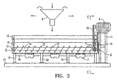
- Figure 1 which is a cross-section through plane C-C of Figure 3
- a receptacle being a hollow container in which materials are processed
- a motorized auger or helical screw conveyor 13 FIG. 3
- a plurality of vibrators 7 are mounted.
- An elongated support frame 16 extends generally beneath the trough 19 and comprises the following: a pair of laterally spaced, longitudinally extending members 30; a plurality of spring-mount pegs 18 projecting generally vertically upwardly from the longitudinally extending members to support and operatively connect the trough 19 to the support frame 16; a plurality of transversely extending cross-members 32, and a plurality of vertically extending support members 34.
- a plurality of springs 5 extend from support frame 16 and over the pegs 18 to isolate the support frame 16 from the vibrations produced by the vibrators 7.
- FIG 3 shows the motorized helical screw conveyor 13 mounted onto the conveyor frame 15 having a thrust end (marked as “A” in Figures 2 and 3) and a discharge end (marked as “B” in Figures 2 and 3) and a pair of downwardly depending support elements 31.
- Any of a multitude of means known within the art may be used to rotate the central shaft 14 of the helical screw conveyor 13.
- the central shaft 14 is rotated by a drive chain 10 which extends from a motor 9 into the trough 19 and around the central shaft 14.
- a plurality of vibrators 7 are suspended below and from trough 19 by means of a plurality of yokes 6 attached to trough 19.
- the entire invention is mounted on a skid 17 that supports both the elongated support frame 16 and the conveyor frame 15 and comprises a pair of laterally spaced, longitudinally extending base members and a pair of transversely extending cross-members.
- contaminated soil is stored in a pile and transported to and into a feed hopper 8 by way of a front-end loader.
- Feed hopper 8 is then movable by overhead crane or the like to distribute the contaminated soil along the length of trough 19.
- Figure 3 shows trough 19 as an elongated, narrow, U-shaped receptacle into which the contaminated soil is introduced by means of the feed hopper 8 and from which the cleaned soil is removed through a butterfly valve 12 at its discharge end (marked as "B" in Figures 2 and 3).
- the volume of contaminated soil introduced should be such that the contaminated soil fills trough 19 throughout the length of trough 19 to at least the level designated Limit A in Fig. 1.
- the helical screw conveyor 13 is activated immediately prior to or upon the introduction of the contaminated soil into trough 19.
- fluid is introduced into trough 19 by any of a multitude of means known within the art, but preferably by means of the fluid inlet 2 located towards the thrust end (marked as "A" in Figures 2 and 3) of trough 19.
- the volume of fluid introduced should be such that the admixture fills trough 19 throughout the length of trough 19 to at least the level indicated by Limit B.
- the fluid can be at or below ambient temperature but preferably is at least at the temperature of the contaminated soil and most preferably is at least 60 degrees Celsius.
- the fluid is fresh water with or without any or all of the following additives: a surfactant to aid in separation of the hydrocarbons adsorbed or entrained in the contaminated soil; an oil; dissolved solids, preferably inorganic salts such as sodium chloride, to increase the density of the fluid to aid in floating the hydrocarbons; or a gas dissolved in the fluid to increase the flotation effect.
- a surfactant to aid in separation of the hydrocarbons adsorbed or entrained in the contaminated soil
- an oil dissolved solids, preferably inorganic salts such as sodium chloride, to increase the density of the fluid to aid in floating the hydrocarbons
- a gas dissolved in the fluid to increase the flotation effect.
- a light oil such as coker gas oil
- a salt such as sodium chloride can be dissolved in the admixture to increase the density of the separated fluid phase. Most hydrocarbons will float above such a brine solution, which has a density of 1.2 g/l in normal conditions. The brine can be recycled in order to minimize salt consumption.
- the fluid-to-contaminated-soil ratio is variable and is dependent on a myriad of factors, including but not limited to, the viscosity of the hydrocarbons, the mineral composition of the contaminated soil, the particulate sizes of the mineral matter in the contaminated soil, the temperature of the fluid, the ambient temperature, etc.
- the volumetric percentage ratio of fluid to solid in the admixture can range from 40:60 to 90:10, more preferably between 50:50 and 70:30, and most preferably at 60:40.
- the method of the invention entails the creation of an aqueous admixture within trough 19 by the mixing of the contaminated soil and the fluid.
- the aforesaid additives can then be introduced into the admixture, either individually in any combination and sequence or collectively, by any of a multitude of means known within the art.
- the fluid additives are introduced into trough 19 through the additive injection line 3.
- the mixing that consolidates the contaminated soil, the fluid, and the additives (if used) into an aqueous admixture is effected by means of helical screw conveyor 13; however, such mixing may also be accomplished using other processes known within the art, including impellers, rakes, screw assemblies, stirrers, etc.
- helical screw conveyor 13 transports the admixture from the thrust end (marked as "A” in Figures 2 and 3) to the discharge end (marked as "B" in Figures 2 and 3) of trough 19 and back.
- such transportation is accomplished by means of a reversible motor 9 mounted on a stand 11 at and near the thrust end (marked as "A" in Figures 2 and 3) of the conveyor frame.
- the reversible motor 9 drives the helical screw conveyor 13 in one direction - be it clockwise or counter clockwise - for a defined period of time and thereafter drives helical screw conveyor 13 in the opposite direction for a defined period of time, which may or may not be equal to the initial period of time.
- the defined period of time may range from 10 to 300 seconds, more preferably between 100 to 200 seconds, and most preferably at 150 seconds.
- the admixture is vibrated by means of the plurality of vibrators 7 suspended below trough 19; however, such vibration may also be accomplished using other means known within the art, including vibrating rods, sonic mixers, shakers, etc.
- the number of vibrators 7 is dependent on a myriad of factors, including but not limited to, the mass of the contaminated soil, the particulate sizes of the mineral matter in the contaminated soil, the volume of the trough 19, the length of the trough 19, the output of each individual vibrator, etc. Thus the number of vibrators can vary. As a general rule and per four lineal meters of trough 19, 1 to 6 vibrators can be used, more preferably 2 to 6 vibrators, and most preferably 3 vibrators.
- the period of time the helical screw conveyor 13 is engaged prior to the activation of the vibrators 7 may range from 10 to 60 seconds, more preferably between 20 to 45 seconds, and most preferably at 30 seconds. As well, the period of time that the vibrators 7 are engaged may range from 10 to 60 seconds, more preferably between 20 to 45 seconds, and most preferably at 30 seconds. In the preferred embodiment, this process is repeated at least three times.
- the helical screw conveyor 13 is then deactivated while vibrators 7 remain engaged, and the separated floating hydrocarbons are thereafter eluted by any of a multitude of means known within the art, whereby the lighter floating hydrocarbons may be extracted continuously or periodically.
- additional fluids are added into trough 19 through fluid inlet 2 such that the level of fluid in trough 19 rises above Limit B thereby causing the lighter floating hydrocarbons to overflow into either or both of the discharge trays 4 located on either side of the length of said trough 19.
- the remaining fluids in trough 19 are then removed by way of the fluid outlet 1 and the remaining solids in said trough 19 are removed by engaging the helical screw conveyor 13 and conveying such solids to and through butterfly valve 12 located at the discharge end (marked as "B" in Figures 2 and 3) of trough 19.
- the present invention relates to a method of separating a hydrocarbon from particulate matter and is useful in the petroleum exploration and production industries.
Landscapes
- Chemical & Material Sciences (AREA)
- Engineering & Computer Science (AREA)
- Chemical Kinetics & Catalysis (AREA)
- Life Sciences & Earth Sciences (AREA)
- Mechanical Engineering (AREA)
- Acoustics & Sound (AREA)
- Physics & Mathematics (AREA)
- Soil Sciences (AREA)
- Environmental & Geological Engineering (AREA)
- Processing Of Solid Wastes (AREA)
- Organic Low-Molecular-Weight Compounds And Preparation Thereof (AREA)
- Physical Or Chemical Processes And Apparatus (AREA)
- Liquid Carbonaceous Fuels (AREA)
Claims (39)
- Procédé permettant de séparer un hydrocarbure d'un matériau particulaire comprenant les étapes consistant à :(a) introduire un fluide dans le matériau particulaire dans un récipient, dans lequel ledit matériau contient un hydrocarbure et ledit fluide contient de l'eau ;(b) mélanger ledit fluide et ledit matériau pour former un mélange dans ledit récipient ;(c) après une période initiale de mélange, appliquer alternativement des vibrations audit mélange dans ledit récipient puis cesser les vibrations tout en continuant à mélanger ; et(d) séparer ledit hydrocarbure dudit mélange fluide par flottation.
- Procédé selon la revendication 1 comprenant les étapes supplémentaires consistant à :(e) enlever ledit fluide dudit mélange fluide ; et(f) enlever ledit matériau particulaire dudit récipient.
- Procédé selon la revendication 2 comprenant en outre l'étape de solidification dudit matériau particulaire avant de l'enlever dudit récipient.
- Procédé selon la revendication 1 dans lequel ledit matériau particulaire est compris dans une bouillie avant l'étape (a).
- Procédé selon la revendication 1 dans lequel ledit matériau particulaire est compris dans une émulsion avant l'étape (a).
- Procédé selon la revendication 1 dans lequel ledit mélange est arrêté pendant que les vibrations sont appliquées audit mélange fluide.
- Procédé selon la revendication 1 dans lequel ledit mélange continue pendant que les vibrations sont appliquées audit mélange fluide.
- Procédé selon la revendication 1 dans lequel ledit mélange est effectué par un transporteur à vis hélicoïdale dans ledit récipient.
- Procédé selon la revendication 8 dans lequel ledit transporteur à vis hélicoïdale transporte ledit matériau particulaire horizontalement tout en effectuant le mélange.
- Procédé selon la revendication 9 dans lequel ledit récipient est une cuve.
- Procédé selon la revendication 10 dans lequel ledit transporteur à vis inverse périodiquement sa direction pendant le mélange.
- Procédé selon la revendication 1 dans lequel il existe au moins trois périodes d'application de vibrations audit mélange fluide.
- Procédé selon la revendication 12 dans lequel les durées desdites périodes d'application de vibrations audit mélange fluide sont comprises entre 10 et 60 secondes.
- Procédé selon la revendication 10 dans lequel ledit hydrocarbure est séparé par flottation par-dessus les bordures supérieures de la cuve.
- Procédé selon la revendication 14 comprenant les étapes supplémentaires consistant à :(e) enlever ledit fluide dudit mélange fluide ; et(f) enlever ledit matériau particulaire de ladite cuve en convoyant ledit matériau au moyen dudit transporteur à vis.
- Procédé selon la revendication 1 comprenant l'étape supplémentaire de cessation dudit mélange puis d'application d'une période de vibrations avant ladite étape de séparation.
- Procédé selon la revendication 1 dans lequel ledit matériau particulaire est un sol.
- Procédé selon la revendication 17 dans lequel ledit fluide contient de l'eau.
- Procédé selon la revendication 18 comprenant l'étape supplémentaire de liquéfaction dudit sol et dudit hydrocarbure dans ledit mélange fluide pour former une bouillie aqueuse.
- Procédé selon la revendication 1 dans lequel un tensioactif est introduit dans ledit mélange fluide.
- Procédé selon la revendication 1 dans lequel une huile adaptée pour provoquer la flottation des hydrocarbures lourds dans ledit mélange fluide est introduite dans ledit mélange fluide.
- Procédé selon la revendication 1 dans lequel un solide dissous est introduit dans ledit mélange fluide.
- Procédé selon la revendication 1 dans lequel ledit fluide contient de l'eau et un tensioactif.
- Procédé selon la revendication 1 dans lequel ledit fluide contient de l'eau et au moins un solide dissous afin d'augmenter la densité dudit liquide.
- Procédé selon la revendication 1 dans lequel ledit fluide contient de l'eau, un tensioactif et au moins un solide dissous afin d'augmenter la densité dudit liquide.
- Procédé selon la revendication 1 dans lequel ledit fluide contient de l'eau salée.
- Procédé selon la revendication 1 dans lequel ledit fluide contient de l'eau salée et un tensioactif.
- Procédé selon la revendication 1 dans lequel ledit fluide contient de l'eau salée et au moins un solide dissous qui augmente la densité dudit liquide.
- Procédé selon la revendication 1 dans lequel ledit fluide contient de l'eau salée, un tensioactif et au moins un solide dissous qui augmente la densité dudit liquide.
- Procédé selon les revendications 20, 23, 25, 27 ou 29 dans lequel ledit tensioactif est choisi parmi le savon, le crésylate, le sulfure, le carbonate de sodium, l'hydroxyde de sodium, le silicate de sodium, ou un électrolyte portant une charge électrique.
- Procédé selon les revendications 22, 24, 28 ou 29 dans lequel ledit solide dissous contient un sel inorganique.
- Procédé selon les revendications 22, 24, 28 ou 29 dans lequel ledit solide dissous contient du chlorure de sodium.
- Procédé selon la revendication 21 dans lequel ladite huile est une huile légère.
- Procédé selon la revendication 21 dans lequel ladite huile est une huile de cokéfaction.
- Procédé selon la revendication 1 dans lequel ledit fluide contient en outre un gaz dissous.
- Procédé selon la revendication 1 dans lequel la quantité de fluide utilisée est en excès par rapport à la quantité de matériau particulaire utilisé.
- Procédé selon la revendication 19 dans lequel ladite suspension aqueuse présente un rapport de pourcentage volumétrique du fluide par rapport au matériau particulaire de 60:40.
- Procédé selon la revendication 19 dans lequel ladite suspension aqueuse a une température comprise entre la température ambiante et 50°C.
- Procédé selon la revendication 19 dans lequel ladite suspension aqueuse a une température d'au moins 60°C.
Applications Claiming Priority (3)
| Application Number | Priority Date | Filing Date | Title |
|---|---|---|---|
| US877086 | 2001-06-11 | ||
| US09/877,086 US6904919B2 (en) | 2001-06-11 | 2001-06-11 | Apparatus and method for separating substances from particulate solids |
| PCT/CA2002/000878 WO2002100508A1 (fr) | 2001-06-11 | 2002-06-10 | Dispositif et procede d'extraction de substances a partir de solides particulaires |
Publications (2)
| Publication Number | Publication Date |
|---|---|
| EP1401552A1 EP1401552A1 (fr) | 2004-03-31 |
| EP1401552B1 true EP1401552B1 (fr) | 2006-04-26 |
Family
ID=25369224
Family Applications (1)
| Application Number | Title | Priority Date | Filing Date |
|---|---|---|---|
| EP02737691A Expired - Lifetime EP1401552B1 (fr) | 2001-06-11 | 2002-06-10 | Dispositif et procede d'extraction de substances a partir de solides particulaires |
Country Status (10)
| Country | Link |
|---|---|
| US (2) | US6904919B2 (fr) |
| EP (1) | EP1401552B1 (fr) |
| CN (1) | CN100415334C (fr) |
| AT (1) | ATE324165T1 (fr) |
| AU (1) | AU2002312679B2 (fr) |
| CA (1) | CA2450242C (fr) |
| DE (1) | DE60210966D1 (fr) |
| MX (1) | MXPA03011605A (fr) |
| NO (1) | NO330557B1 (fr) |
| WO (1) | WO2002100508A1 (fr) |
Families Citing this family (25)
| Publication number | Priority date | Publication date | Assignee | Title |
|---|---|---|---|---|
| US6904919B2 (en) * | 2001-06-11 | 2005-06-14 | Newtech Commercialization Ltd. | Apparatus and method for separating substances from particulate solids |
| GB0321023D0 (en) * | 2003-09-09 | 2003-10-08 | Star Environmental Systems Ltd | Waste solid cleaning |
| US7758746B2 (en) | 2006-10-06 | 2010-07-20 | Vary Petrochem, Llc | Separating compositions and methods of use |
| US8062512B2 (en) * | 2006-10-06 | 2011-11-22 | Vary Petrochem, Llc | Processes for bitumen separation |
| PL2069467T3 (pl) | 2006-10-06 | 2015-02-27 | Vary Petrochem Llc | Kompozycje wydzielające i sposoby stosowania |
| CA2605053A1 (fr) * | 2007-10-02 | 2009-04-02 | Institut National De La Recherche Scientifique (Inrs) | Traitement de milieux contamines par des composes organiques hydrophobes et des metaux |
| US20100176033A1 (en) * | 2009-01-15 | 2010-07-15 | Rapp Gary L | System for removing tar oil from sand and method of extracting oil from sand |
| CN101991970B (zh) * | 2009-08-28 | 2013-06-19 | 新奥科技发展有限公司 | 物料连续提取系统和方法 |
| US20110170953A1 (en) * | 2010-01-08 | 2011-07-14 | Diamond Charles M | Method and system for removing liquid hydrocarbons from contaminated soil |
| NO332327B1 (no) * | 2010-10-12 | 2012-08-27 | Cubility As | Renseinnretning |
| US9266117B2 (en) * | 2011-09-20 | 2016-02-23 | Jo-Ann Reif | Process and system for treating particulate solids |
| US8845233B2 (en) | 2011-10-13 | 2014-09-30 | Empire Technology Development Llc | Soil remediation |
| GB2534528A (en) * | 2014-02-19 | 2016-07-27 | Halliburton Energy Services Inc | Clean-up fluid for wellbore particles containing an environmentally-friendly surfactant |
| CN103978022A (zh) * | 2014-04-18 | 2014-08-13 | 杭州师范大学 | 一种用于土壤重金属阻控技术研究的装置 |
| US10967300B2 (en) * | 2017-08-29 | 2021-04-06 | Green Flow Industries, LLC | Transportable separation and monitoring apparatus with auger |
| US10857488B1 (en) * | 2017-09-15 | 2020-12-08 | Del Corporation | System for separating solids from a fluid stream |
| CN108326020A (zh) * | 2018-01-29 | 2018-07-27 | 李子琦 | 一种间歇注液的提升式土壤污染粉碎搅拌处理装置 |
| CN109304047A (zh) * | 2018-11-16 | 2019-02-05 | 林爱花 | 一种西药剂固态提取装置 |
| RU195503U1 (ru) * | 2019-05-31 | 2020-01-29 | Федеральное государственное бюджетное образовательное учреждение высшего образования "Волгоградский государственный технический университет" (ВолгГТУ) | Массообменный аппарат непрерывного действия |
| RU195502U1 (ru) * | 2019-05-31 | 2020-01-29 | Федеральное государственное бюджетное образовательное учреждение высшего образования "Волгоградский государственный технический университет" (ВолгГТУ) | Тепломассообменный аппарат |
| RU195520U1 (ru) * | 2019-05-31 | 2020-01-30 | Федеральное государственное бюджетное образовательное учреждение высшего образования "Волгоградский государственный технический университет" (ВолгГТУ) | Массообменный аппарат для электросорбционных процессов |
| EP3885021B1 (fr) * | 2020-03-27 | 2024-10-09 | Bauer Resources GmbH | Procédé et installation de traitement de nettoyage d'un matériaux contaminés |
| KR102134251B1 (ko) * | 2020-04-03 | 2020-07-15 | 박도균 | 오염토 세척 정화 시스템 |
| RU2764851C1 (ru) * | 2021-02-10 | 2022-01-21 | Федеральное государственное бюджетное образовательное учреж-дение высшего образования "Волгоградский государственный технический университет" (ВолгГТУ) | Тепломассообменный аппарат для сушки дисперсных материалов |
| GB2640464A (en) * | 2024-04-19 | 2025-10-22 | Acca Tech Limited | Method and system for treating contaminated materials |
Family Cites Families (20)
| Publication number | Priority date | Publication date | Assignee | Title |
|---|---|---|---|---|
| CA1137005A (fr) * | 1979-06-08 | 1982-12-07 | Research Council Of Alberta | Transport de petrole brut lourd par pipeline |
| US4443322A (en) * | 1980-12-08 | 1984-04-17 | Teksonix, Inc. | Continuous process and apparatus for separating hydrocarbons from earth particles and sand |
| US4929341A (en) * | 1984-07-24 | 1990-05-29 | Source Technology Earth Oils, Inc. | Process and system for recovering oil from oil bearing soil such as shale and tar sands and oil produced by such process |
| DE3619716C1 (de) | 1986-06-12 | 1988-02-04 | Ifs Ing Gmbh | Vorrichtung zum Abtrennen von an Schuettgut gebundenen Fremdstoffen |
| US5303871A (en) | 1988-02-08 | 1994-04-19 | Biotrol, Incorporated | Process for treating contaminated soil |
| CA1329319C (fr) | 1989-02-07 | 1994-05-10 | Carlos J. Valdes | Extraction d'huile des deblais de forage contamines aux hydrocarbures |
| US5264118A (en) * | 1989-11-24 | 1993-11-23 | Alberta Energy Company, Ltd. | Pipeline conditioning process for mined oil-sand |
| EP0465620B1 (fr) | 1990-01-29 | 1995-04-12 | Preussag Aktiengesellschaft | Procede de deshuilage des produits solides a particules de faible dimension, en particulier les residus de production contenant des metaux et les sols souilles |
| DE4039109A1 (de) * | 1990-12-07 | 1992-06-11 | Metallgesellschaft Ag | Verfahren zur aufbereitung von kontaminierten boeden |
| US5199997A (en) * | 1991-06-13 | 1993-04-06 | Clnzall Corporation | Treatment of hydrocarbon-contaminated particulate materials |
| DE4137014A1 (de) | 1991-11-11 | 1993-05-13 | Henkel Kgaa | Entfernung von kohlenwasserstoffen, kuehlschmierstoffen und/oder oelen von der oberflaeche feiner partikel |
| US5344255A (en) * | 1992-01-03 | 1994-09-06 | Itex Enterprises, Inc. | Oil, water and sand separator |
| US5637152A (en) | 1992-05-07 | 1997-06-10 | Separation Oil Services, Inc. | Soil washing apparatus and method |
| US6110359A (en) * | 1995-10-17 | 2000-08-29 | Mobil Oil Corporation | Method for extracting bitumen from tar sands |
| US5951456A (en) * | 1997-05-16 | 1999-09-14 | Scott; Harold W. | Ultrasonic methods and apparatus for separating materials in a fluid mixture |
| US6214236B1 (en) * | 1997-07-01 | 2001-04-10 | Robert Scalliet | Process for breaking an emulsion |
| US6056882A (en) * | 1997-07-01 | 2000-05-02 | Scalliet; Robert | Process of breaking a sludge emulsion with a ball mill followed by separation |
| US5968370A (en) * | 1998-01-14 | 1999-10-19 | Prowler Environmental Technology, Inc. | Method of removing hydrocarbons from contaminated sludge |
| CA2228098A1 (fr) * | 1998-01-29 | 1999-07-29 | Ajay Singh | Traitement de sol contamine par des hydrocarbures ou par leurs residus |
| US6904919B2 (en) * | 2001-06-11 | 2005-06-14 | Newtech Commercialization Ltd. | Apparatus and method for separating substances from particulate solids |
-
2001
- 2001-06-11 US US09/877,086 patent/US6904919B2/en not_active Expired - Lifetime
-
2002
- 2002-06-10 CA CA2450242A patent/CA2450242C/fr not_active Expired - Lifetime
- 2002-06-10 AT AT02737691T patent/ATE324165T1/de not_active IP Right Cessation
- 2002-06-10 WO PCT/CA2002/000878 patent/WO2002100508A1/fr not_active Ceased
- 2002-06-10 CN CNB028152719A patent/CN100415334C/zh not_active Expired - Fee Related
- 2002-06-10 MX MXPA03011605A patent/MXPA03011605A/es active IP Right Grant
- 2002-06-10 EP EP02737691A patent/EP1401552B1/fr not_active Expired - Lifetime
- 2002-06-10 DE DE60210966T patent/DE60210966D1/de not_active Expired - Lifetime
- 2002-06-10 AU AU2002312679A patent/AU2002312679B2/en not_active Ceased
-
2003
- 2003-12-11 US US10/732,409 patent/US7118631B2/en not_active Expired - Lifetime
- 2003-12-11 NO NO20035536A patent/NO330557B1/no not_active IP Right Cessation
Also Published As
| Publication number | Publication date |
|---|---|
| NO20035536D0 (no) | 2003-12-11 |
| DE60210966D1 (de) | 2006-06-01 |
| CA2450242A1 (fr) | 2002-12-19 |
| AU2002312679B2 (en) | 2007-11-29 |
| CA2450242C (fr) | 2010-12-07 |
| US20050056300A1 (en) | 2005-03-17 |
| ATE324165T1 (de) | 2006-05-15 |
| US7118631B2 (en) | 2006-10-10 |
| NO330557B1 (no) | 2011-05-16 |
| EP1401552A1 (fr) | 2004-03-31 |
| US6904919B2 (en) | 2005-06-14 |
| WO2002100508A1 (fr) | 2002-12-19 |
| CN100415334C (zh) | 2008-09-03 |
| US20020185158A1 (en) | 2002-12-12 |
| CN1538864A (zh) | 2004-10-20 |
| MXPA03011605A (es) | 2005-03-07 |
Similar Documents
| Publication | Publication Date | Title |
|---|---|---|
| EP1401552B1 (fr) | Dispositif et procede d'extraction de substances a partir de solides particulaires | |
| AU2002312679A1 (en) | Apparatus and method for separating substances from particulate solids | |
| US5882524A (en) | Treatment of oil-contaminated particulate materials | |
| US7594996B2 (en) | Petroleum recovery and cleaning system and process | |
| US4966685A (en) | Process for extracting oil from tar sands | |
| US6576145B2 (en) | Method of separating hydrocarbons from mineral substrates | |
| US5570749A (en) | Drilling fluid remediation system | |
| US8440727B2 (en) | Hydrocarbon extraction by oleophilic beads from aqueous mixtures | |
| WO2015005806A1 (fr) | Procédé et appareil de récupération de liquides non aqueux précieux ou dangereux à partir de suspensions | |
| US10041315B2 (en) | Apparatus and method for removing and recovering oil from solids | |
| AU2004269974B2 (en) | Waste solid cleaning | |
| CA2719268A1 (fr) | Appareil et methode a micro-ondes pour la desemulsification | |
| US20160263494A1 (en) | Method and apparatus for treatment of oil based drilling fluid | |
| US5391018A (en) | Process for washing contaminated soil | |
| US7678201B2 (en) | Composition and process for the removal and recovery of hydrocarbons from substrates | |
| US5986147A (en) | Method and solution for removal of poly chlorinated biphenyl | |
| US20060104157A1 (en) | Flow-through mixing apparatus | |
| CA2876745A1 (fr) | Procede de recuperation et d'extraction utilisant des solvants a base d'agrumes | |
| JPT staff | Invert-Fluid Flocculation: A Method for Recycling Drilling Fluid | |
| US20190023991A1 (en) | Hydrocarbon extraction by oleophilic beads from aqueous mixtures | |
| McCosh et al. | Unique Electrophoresis Technology to Recycle Invert Emulsion Drilling Fluids | |
| CA2838644A1 (fr) | Systeme de lavage de remblais de forage |
Legal Events
| Date | Code | Title | Description |
|---|---|---|---|
| PUAI | Public reference made under article 153(3) epc to a published international application that has entered the european phase |
Free format text: ORIGINAL CODE: 0009012 |
|
| 17P | Request for examination filed |
Effective date: 20040112 |
|
| AK | Designated contracting states |
Kind code of ref document: A1 Designated state(s): AT BE CH CY DE DK ES FI FR GB GR IE IT LI LU MC NL PT SE TR |
|
| AX | Request for extension of the european patent |
Extension state: AL LT LV MK RO SI |
|
| 17Q | First examination report despatched |
Effective date: 20040621 |
|
| GRAP | Despatch of communication of intention to grant a patent |
Free format text: ORIGINAL CODE: EPIDOSNIGR1 |
|
| GRAS | Grant fee paid |
Free format text: ORIGINAL CODE: EPIDOSNIGR3 |
|
| GRAA | (expected) grant |
Free format text: ORIGINAL CODE: 0009210 |
|
| AK | Designated contracting states |
Kind code of ref document: B1 Designated state(s): AT BE CH CY DE DK ES FI FR GB GR IE IT LI LU MC NL PT SE TR |
|
| PG25 | Lapsed in a contracting state [announced via postgrant information from national office to epo] |
Ref country code: IT Free format text: LAPSE BECAUSE OF FAILURE TO SUBMIT A TRANSLATION OF THE DESCRIPTION OR TO PAY THE FEE WITHIN THE PRESCRIBED TIME-LIMIT;WARNING: LAPSES OF ITALIAN PATENTS WITH EFFECTIVE DATE BEFORE 2007 MAY HAVE OCCURRED AT ANY TIME BEFORE 2007. THE CORRECT EFFECTIVE DATE MAY BE DIFFERENT FROM THE ONE RECORDED. Effective date: 20060426 Ref country code: CH Free format text: LAPSE BECAUSE OF FAILURE TO SUBMIT A TRANSLATION OF THE DESCRIPTION OR TO PAY THE FEE WITHIN THE PRESCRIBED TIME-LIMIT Effective date: 20060426 Ref country code: AT Free format text: LAPSE BECAUSE OF FAILURE TO SUBMIT A TRANSLATION OF THE DESCRIPTION OR TO PAY THE FEE WITHIN THE PRESCRIBED TIME-LIMIT Effective date: 20060426 Ref country code: LI Free format text: LAPSE BECAUSE OF FAILURE TO SUBMIT A TRANSLATION OF THE DESCRIPTION OR TO PAY THE FEE WITHIN THE PRESCRIBED TIME-LIMIT Effective date: 20060426 Ref country code: NL Free format text: LAPSE BECAUSE OF FAILURE TO SUBMIT A TRANSLATION OF THE DESCRIPTION OR TO PAY THE FEE WITHIN THE PRESCRIBED TIME-LIMIT Effective date: 20060426 Ref country code: FI Free format text: LAPSE BECAUSE OF FAILURE TO SUBMIT A TRANSLATION OF THE DESCRIPTION OR TO PAY THE FEE WITHIN THE PRESCRIBED TIME-LIMIT Effective date: 20060426 Ref country code: BE Free format text: LAPSE BECAUSE OF FAILURE TO SUBMIT A TRANSLATION OF THE DESCRIPTION OR TO PAY THE FEE WITHIN THE PRESCRIBED TIME-LIMIT Effective date: 20060426 |
|
| REG | Reference to a national code |
Ref country code: GB Ref legal event code: FG4D |
|
| REG | Reference to a national code |
Ref country code: IE Ref legal event code: FG4D |
|
| REF | Corresponds to: |
Ref document number: 60210966 Country of ref document: DE Date of ref document: 20060601 Kind code of ref document: P |
|
| PG25 | Lapsed in a contracting state [announced via postgrant information from national office to epo] |
Ref country code: IE Free format text: LAPSE BECAUSE OF NON-PAYMENT OF DUE FEES Effective date: 20060612 |
|
| PG25 | Lapsed in a contracting state [announced via postgrant information from national office to epo] |
Ref country code: MC Free format text: LAPSE BECAUSE OF NON-PAYMENT OF DUE FEES Effective date: 20060630 |
|
| PG25 | Lapsed in a contracting state [announced via postgrant information from national office to epo] |
Ref country code: DK Free format text: LAPSE BECAUSE OF FAILURE TO SUBMIT A TRANSLATION OF THE DESCRIPTION OR TO PAY THE FEE WITHIN THE PRESCRIBED TIME-LIMIT Effective date: 20060726 Ref country code: SE Free format text: LAPSE BECAUSE OF FAILURE TO SUBMIT A TRANSLATION OF THE DESCRIPTION OR TO PAY THE FEE WITHIN THE PRESCRIBED TIME-LIMIT Effective date: 20060726 |
|
| PG25 | Lapsed in a contracting state [announced via postgrant information from national office to epo] |
Ref country code: DE Free format text: LAPSE BECAUSE OF FAILURE TO SUBMIT A TRANSLATION OF THE DESCRIPTION OR TO PAY THE FEE WITHIN THE PRESCRIBED TIME-LIMIT Effective date: 20060727 |
|
| PG25 | Lapsed in a contracting state [announced via postgrant information from national office to epo] |
Ref country code: ES Free format text: LAPSE BECAUSE OF FAILURE TO SUBMIT A TRANSLATION OF THE DESCRIPTION OR TO PAY THE FEE WITHIN THE PRESCRIBED TIME-LIMIT Effective date: 20060806 |
|
| PG25 | Lapsed in a contracting state [announced via postgrant information from national office to epo] |
Ref country code: PT Free format text: LAPSE BECAUSE OF FAILURE TO SUBMIT A TRANSLATION OF THE DESCRIPTION OR TO PAY THE FEE WITHIN THE PRESCRIBED TIME-LIMIT Effective date: 20060926 |
|
| REG | Reference to a national code |
Ref country code: CH Ref legal event code: PL |
|
| NLV1 | Nl: lapsed or annulled due to failure to fulfill the requirements of art. 29p and 29m of the patents act | ||
| PLBE | No opposition filed within time limit |
Free format text: ORIGINAL CODE: 0009261 |
|
| STAA | Information on the status of an ep patent application or granted ep patent |
Free format text: STATUS: NO OPPOSITION FILED WITHIN TIME LIMIT |
|
| 26N | No opposition filed |
Effective date: 20070129 |
|
| EN | Fr: translation not filed | ||
| PG25 | Lapsed in a contracting state [announced via postgrant information from national office to epo] |
Ref country code: FR Free format text: LAPSE BECAUSE OF FAILURE TO SUBMIT A TRANSLATION OF THE DESCRIPTION OR TO PAY THE FEE WITHIN THE PRESCRIBED TIME-LIMIT Effective date: 20070309 Ref country code: GR Free format text: LAPSE BECAUSE OF FAILURE TO SUBMIT A TRANSLATION OF THE DESCRIPTION OR TO PAY THE FEE WITHIN THE PRESCRIBED TIME-LIMIT Effective date: 20060727 |
|
| PG25 | Lapsed in a contracting state [announced via postgrant information from national office to epo] |
Ref country code: LU Free format text: LAPSE BECAUSE OF NON-PAYMENT OF DUE FEES Effective date: 20060610 Ref country code: TR Free format text: LAPSE BECAUSE OF FAILURE TO SUBMIT A TRANSLATION OF THE DESCRIPTION OR TO PAY THE FEE WITHIN THE PRESCRIBED TIME-LIMIT Effective date: 20060426 |
|
| PG25 | Lapsed in a contracting state [announced via postgrant information from national office to epo] |
Ref country code: FR Free format text: LAPSE BECAUSE OF FAILURE TO SUBMIT A TRANSLATION OF THE DESCRIPTION OR TO PAY THE FEE WITHIN THE PRESCRIBED TIME-LIMIT Effective date: 20060426 Ref country code: CY Free format text: LAPSE BECAUSE OF FAILURE TO SUBMIT A TRANSLATION OF THE DESCRIPTION OR TO PAY THE FEE WITHIN THE PRESCRIBED TIME-LIMIT Effective date: 20060426 |
|
| REG | Reference to a national code |
Ref country code: GB Ref legal event code: 732E Free format text: REGISTERED BETWEEN 20090528 AND 20090603 |
|
| PGFP | Annual fee paid to national office [announced via postgrant information from national office to epo] |
Ref country code: GB Payment date: 20160627 Year of fee payment: 15 |
|
| GBPC | Gb: european patent ceased through non-payment of renewal fee |
Effective date: 20170610 |
|
| PG25 | Lapsed in a contracting state [announced via postgrant information from national office to epo] |
Ref country code: GB Free format text: LAPSE BECAUSE OF NON-PAYMENT OF DUE FEES Effective date: 20170610 |