EP1401373B1 - Cpr assist device with pressure bladder feedback - Google Patents
Cpr assist device with pressure bladder feedback Download PDFInfo
- Publication number
- EP1401373B1 EP1401373B1 EP02746448A EP02746448A EP1401373B1 EP 1401373 B1 EP1401373 B1 EP 1401373B1 EP 02746448 A EP02746448 A EP 02746448A EP 02746448 A EP02746448 A EP 02746448A EP 1401373 B1 EP1401373 B1 EP 1401373B1
- Authority
- EP
- European Patent Office
- Prior art keywords
- belt
- motor
- compression
- chest
- spool
- Prior art date
- Legal status (The legal status is an assumption and is not a legal conclusion. Google has not performed a legal analysis and makes no representation as to the accuracy of the status listed.)
- Expired - Lifetime
Links
- 238000007906 compression Methods 0.000 claims abstract description 325
- 230000006835 compression Effects 0.000 claims abstract description 324
- 210000000038 chest Anatomy 0.000 claims abstract description 168
- 230000007246 mechanism Effects 0.000 claims description 26
- 230000000694 effects Effects 0.000 claims description 17
- 239000008280 blood Substances 0.000 claims description 10
- 210000004369 blood Anatomy 0.000 claims description 10
- 230000000747 cardiac effect Effects 0.000 claims description 6
- 210000004177 elastic tissue Anatomy 0.000 claims 1
- 210000000115 thoracic cavity Anatomy 0.000 abstract description 17
- 230000008859 change Effects 0.000 description 33
- 238000010586 diagram Methods 0.000 description 31
- 238000004891 communication Methods 0.000 description 29
- 230000008878 coupling Effects 0.000 description 28
- 238000010168 coupling process Methods 0.000 description 28
- 238000005859 coupling reaction Methods 0.000 description 28
- 238000002680 cardiopulmonary resuscitation Methods 0.000 description 25
- 208000010496 Heart Arrest Diseases 0.000 description 15
- 230000000981 bystander Effects 0.000 description 14
- 238000000034 method Methods 0.000 description 14
- 230000002441 reversible effect Effects 0.000 description 14
- 230000029058 respiratory gaseous exchange Effects 0.000 description 13
- 210000001562 sternum Anatomy 0.000 description 13
- QVGXLLKOCUKJST-UHFFFAOYSA-N atomic oxygen Chemical compound [O] QVGXLLKOCUKJST-UHFFFAOYSA-N 0.000 description 12
- 238000006073 displacement reaction Methods 0.000 description 12
- 239000001301 oxygen Substances 0.000 description 12
- 229910052760 oxygen Inorganic materials 0.000 description 12
- 230000004044 response Effects 0.000 description 12
- 230000009471 action Effects 0.000 description 11
- 210000004712 air sac Anatomy 0.000 description 11
- 238000002347 injection Methods 0.000 description 11
- 239000007924 injection Substances 0.000 description 11
- 239000003814 drug Substances 0.000 description 10
- 208000027418 Wounds and injury Diseases 0.000 description 9
- 230000000875 corresponding effect Effects 0.000 description 9
- 230000006378 damage Effects 0.000 description 9
- 229940079593 drug Drugs 0.000 description 9
- 230000000977 initiatory effect Effects 0.000 description 9
- 208000014674 injury Diseases 0.000 description 9
- 238000012544 monitoring process Methods 0.000 description 8
- 230000017531 blood circulation Effects 0.000 description 7
- 230000033001 locomotion Effects 0.000 description 7
- 201000011244 Acrocallosal syndrome Diseases 0.000 description 6
- 238000000418 atomic force spectrum Methods 0.000 description 6
- 230000006870 function Effects 0.000 description 6
- 239000000463 material Substances 0.000 description 6
- 230000000670 limiting effect Effects 0.000 description 5
- 210000004072 lung Anatomy 0.000 description 5
- 230000008901 benefit Effects 0.000 description 4
- 210000000481 breast Anatomy 0.000 description 4
- 230000001965 increasing effect Effects 0.000 description 4
- 230000003252 repetitive effect Effects 0.000 description 4
- 230000003068 static effect Effects 0.000 description 4
- 230000005540 biological transmission Effects 0.000 description 3
- 230000036772 blood pressure Effects 0.000 description 3
- 239000012530 fluid Substances 0.000 description 3
- 238000009434 installation Methods 0.000 description 3
- 230000002452 interceptive effect Effects 0.000 description 3
- 230000003287 optical effect Effects 0.000 description 3
- 229920001343 polytetrafluoroethylene Polymers 0.000 description 3
- 239000004810 polytetrafluoroethylene Substances 0.000 description 3
- 230000009467 reduction Effects 0.000 description 3
- 210000001991 scapula Anatomy 0.000 description 3
- 238000009423 ventilation Methods 0.000 description 3
- UCTWMZQNUQWSLP-VIFPVBQESA-N (R)-adrenaline Chemical compound CNC[C@H](O)C1=CC=C(O)C(O)=C1 UCTWMZQNUQWSLP-VIFPVBQESA-N 0.000 description 2
- 229930182837 (R)-adrenaline Natural products 0.000 description 2
- 229920006362 Teflon® Polymers 0.000 description 2
- 229920000690 Tyvek Polymers 0.000 description 2
- 239000004775 Tyvek Substances 0.000 description 2
- 210000002376 aorta thoracic Anatomy 0.000 description 2
- 238000013459 approach Methods 0.000 description 2
- 230000006931 brain damage Effects 0.000 description 2
- 231100000874 brain damage Toxicity 0.000 description 2
- 208000029028 brain injury Diseases 0.000 description 2
- 230000002612 cardiopulmonary effect Effects 0.000 description 2
- 230000001413 cellular effect Effects 0.000 description 2
- 230000004087 circulation Effects 0.000 description 2
- 125000004122 cyclic group Chemical group 0.000 description 2
- 230000003247 decreasing effect Effects 0.000 description 2
- 229960005139 epinephrine Drugs 0.000 description 2
- 239000004744 fabric Substances 0.000 description 2
- 239000002783 friction material Substances 0.000 description 2
- 239000007789 gas Substances 0.000 description 2
- 230000001976 improved effect Effects 0.000 description 2
- 230000001939 inductive effect Effects 0.000 description 2
- 230000004048 modification Effects 0.000 description 2
- 238000012986 modification Methods 0.000 description 2
- 210000003205 muscle Anatomy 0.000 description 2
- 238000009987 spinning Methods 0.000 description 2
- 238000012549 training Methods 0.000 description 2
- 206010060874 Aortic rupture Diseases 0.000 description 1
- 229930003347 Atropine Natural products 0.000 description 1
- 206010061386 Chest injury Diseases 0.000 description 1
- 206010014357 Electric shock Diseases 0.000 description 1
- RKUNBYITZUJHSG-UHFFFAOYSA-N Hyosciamin-hydrochlorid Natural products CN1C(C2)CCC1CC2OC(=O)C(CO)C1=CC=CC=C1 RKUNBYITZUJHSG-UHFFFAOYSA-N 0.000 description 1
- 208000034693 Laceration Diseases 0.000 description 1
- NNJVILVZKWQKPM-UHFFFAOYSA-N Lidocaine Chemical compound CCN(CC)CC(=O)NC1=C(C)C=CC=C1C NNJVILVZKWQKPM-UHFFFAOYSA-N 0.000 description 1
- 239000004698 Polyethylene Substances 0.000 description 1
- 208000027790 Rib fracture Diseases 0.000 description 1
- 208000029224 Thoracic injury Diseases 0.000 description 1
- 206010067979 Traumatic liver injury Diseases 0.000 description 1
- 208000007474 aortic aneurysm Diseases 0.000 description 1
- 210000001367 artery Anatomy 0.000 description 1
- RKUNBYITZUJHSG-SPUOUPEWSA-N atropine Chemical compound O([C@H]1C[C@H]2CC[C@@H](C1)N2C)C(=O)C(CO)C1=CC=CC=C1 RKUNBYITZUJHSG-SPUOUPEWSA-N 0.000 description 1
- 229960000396 atropine Drugs 0.000 description 1
- 230000036770 blood supply Effects 0.000 description 1
- 230000037396 body weight Effects 0.000 description 1
- 210000004556 brain Anatomy 0.000 description 1
- AAQOQKQBGPPFNS-UHFFFAOYSA-N bretylium Chemical compound CC[N+](C)(C)CC1=CC=CC=C1Br AAQOQKQBGPPFNS-UHFFFAOYSA-N 0.000 description 1
- 229960002624 bretylium tosilate Drugs 0.000 description 1
- 238000004364 calculation method Methods 0.000 description 1
- 230000002079 cooperative effect Effects 0.000 description 1
- 210000004351 coronary vessel Anatomy 0.000 description 1
- 230000002596 correlated effect Effects 0.000 description 1
- 230000006837 decompression Effects 0.000 description 1
- 230000001419 dependent effect Effects 0.000 description 1
- 238000001514 detection method Methods 0.000 description 1
- 230000001627 detrimental effect Effects 0.000 description 1
- 238000007667 floating Methods 0.000 description 1
- 230000000004 hemodynamic effect Effects 0.000 description 1
- 229960004194 lidocaine Drugs 0.000 description 1
- 210000004705 lumbosacral region Anatomy 0.000 description 1
- 230000013011 mating Effects 0.000 description 1
- 238000005259 measurement Methods 0.000 description 1
- 238000002483 medication Methods 0.000 description 1
- 230000002107 myocardial effect Effects 0.000 description 1
- 208000010125 myocardial infarction Diseases 0.000 description 1
- 230000036961 partial effect Effects 0.000 description 1
- 230000000149 penetrating effect Effects 0.000 description 1
- 229920003023 plastic Polymers 0.000 description 1
- 239000004033 plastic Substances 0.000 description 1
- -1 polyethylene Polymers 0.000 description 1
- 229920000573 polyethylene Polymers 0.000 description 1
- 238000005086 pumping Methods 0.000 description 1
- 238000011084 recovery Methods 0.000 description 1
- 230000001105 regulatory effect Effects 0.000 description 1
- 230000000250 revascularization Effects 0.000 description 1
- 238000005096 rolling process Methods 0.000 description 1
- 230000035939 shock Effects 0.000 description 1
- 230000008054 signal transmission Effects 0.000 description 1
- 239000007787 solid Substances 0.000 description 1
- GOLXNESZZPUPJE-UHFFFAOYSA-N spiromesifen Chemical compound CC1=CC(C)=CC(C)=C1C(C(O1)=O)=C(OC(=O)CC(C)(C)C)C11CCCC1 GOLXNESZZPUPJE-UHFFFAOYSA-N 0.000 description 1
- 210000002784 stomach Anatomy 0.000 description 1
- 238000001356 surgical procedure Methods 0.000 description 1
- 230000004083 survival effect Effects 0.000 description 1
- 230000002459 sustained effect Effects 0.000 description 1
- 238000012360 testing method Methods 0.000 description 1
- 230000001225 therapeutic effect Effects 0.000 description 1
- 238000002560 therapeutic procedure Methods 0.000 description 1
- 230000001960 triggered effect Effects 0.000 description 1
- 238000011144 upstream manufacturing Methods 0.000 description 1
- 208000003663 ventricular fibrillation Diseases 0.000 description 1
- 239000002699 waste material Substances 0.000 description 1
- XLYOFNOQVPJJNP-UHFFFAOYSA-N water Substances O XLYOFNOQVPJJNP-UHFFFAOYSA-N 0.000 description 1
Images


Classifications
-
- A—HUMAN NECESSITIES
- A61—MEDICAL OR VETERINARY SCIENCE; HYGIENE
- A61H—PHYSICAL THERAPY APPARATUS, e.g. DEVICES FOR LOCATING OR STIMULATING REFLEX POINTS IN THE BODY; ARTIFICIAL RESPIRATION; MASSAGE; BATHING DEVICES FOR SPECIAL THERAPEUTIC OR HYGIENIC PURPOSES OR SPECIFIC PARTS OF THE BODY
- A61H31/00—Artificial respiration by a force applied to the chest; Heart stimulation, e.g. heart massage
- A61H31/004—Heart stimulation
- A61H31/005—Heart stimulation with feedback for the user
-
- A—HUMAN NECESSITIES
- A61—MEDICAL OR VETERINARY SCIENCE; HYGIENE
- A61H—PHYSICAL THERAPY APPARATUS, e.g. DEVICES FOR LOCATING OR STIMULATING REFLEX POINTS IN THE BODY; ARTIFICIAL RESPIRATION; MASSAGE; BATHING DEVICES FOR SPECIAL THERAPEUTIC OR HYGIENIC PURPOSES OR SPECIFIC PARTS OF THE BODY
- A61H31/00—Artificial respiration by a force applied to the chest; Heart stimulation, e.g. heart massage
- A61H31/004—Heart stimulation
- A61H31/006—Power driven
-
- A—HUMAN NECESSITIES
- A61—MEDICAL OR VETERINARY SCIENCE; HYGIENE
- A61H—PHYSICAL THERAPY APPARATUS, e.g. DEVICES FOR LOCATING OR STIMULATING REFLEX POINTS IN THE BODY; ARTIFICIAL RESPIRATION; MASSAGE; BATHING DEVICES FOR SPECIAL THERAPEUTIC OR HYGIENIC PURPOSES OR SPECIFIC PARTS OF THE BODY
- A61H31/00—Artificial respiration by a force applied to the chest; Heart stimulation, e.g. heart massage
- A61H31/008—Supine patient supports or bases, e.g. improving air-way access to the lungs
-
- A—HUMAN NECESSITIES
- A61—MEDICAL OR VETERINARY SCIENCE; HYGIENE
- A61N—ELECTROTHERAPY; MAGNETOTHERAPY; RADIATION THERAPY; ULTRASOUND THERAPY
- A61N1/00—Electrotherapy; Circuits therefor
- A61N1/02—Details
- A61N1/04—Electrodes
- A61N1/0404—Electrodes for external use
- A61N1/0472—Structure-related aspects
-
- A—HUMAN NECESSITIES
- A61—MEDICAL OR VETERINARY SCIENCE; HYGIENE
- A61N—ELECTROTHERAPY; MAGNETOTHERAPY; RADIATION THERAPY; ULTRASOUND THERAPY
- A61N1/00—Electrotherapy; Circuits therefor
- A61N1/18—Applying electric currents by contact electrodes
- A61N1/32—Applying electric currents by contact electrodes alternating or intermittent currents
- A61N1/38—Applying electric currents by contact electrodes alternating or intermittent currents for producing shock effects
- A61N1/39—Heart defibrillators
- A61N1/3968—Constructional arrangements, e.g. casings
-
- A—HUMAN NECESSITIES
- A61—MEDICAL OR VETERINARY SCIENCE; HYGIENE
- A61H—PHYSICAL THERAPY APPARATUS, e.g. DEVICES FOR LOCATING OR STIMULATING REFLEX POINTS IN THE BODY; ARTIFICIAL RESPIRATION; MASSAGE; BATHING DEVICES FOR SPECIAL THERAPEUTIC OR HYGIENIC PURPOSES OR SPECIFIC PARTS OF THE BODY
- A61H11/00—Belts, strips or combs for massage purposes
- A61H2011/005—Belts, strips or combs for massage purposes with belt or strap expanding and contracting around an encircled body part
-
- A—HUMAN NECESSITIES
- A61—MEDICAL OR VETERINARY SCIENCE; HYGIENE
- A61H—PHYSICAL THERAPY APPARATUS, e.g. DEVICES FOR LOCATING OR STIMULATING REFLEX POINTS IN THE BODY; ARTIFICIAL RESPIRATION; MASSAGE; BATHING DEVICES FOR SPECIAL THERAPEUTIC OR HYGIENIC PURPOSES OR SPECIFIC PARTS OF THE BODY
- A61H31/00—Artificial respiration by a force applied to the chest; Heart stimulation, e.g. heart massage
- A61H2031/003—Artificial respiration by a force applied to the chest; Heart stimulation, e.g. heart massage with alternated thorax decompression due to lateral compression
-
- A—HUMAN NECESSITIES
- A61—MEDICAL OR VETERINARY SCIENCE; HYGIENE
- A61H—PHYSICAL THERAPY APPARATUS, e.g. DEVICES FOR LOCATING OR STIMULATING REFLEX POINTS IN THE BODY; ARTIFICIAL RESPIRATION; MASSAGE; BATHING DEVICES FOR SPECIAL THERAPEUTIC OR HYGIENIC PURPOSES OR SPECIFIC PARTS OF THE BODY
- A61H2201/00—Characteristics of apparatus not provided for in the preceding codes
- A61H2201/01—Constructive details
- A61H2201/0103—Constructive details inflatable
-
- A—HUMAN NECESSITIES
- A61—MEDICAL OR VETERINARY SCIENCE; HYGIENE
- A61H—PHYSICAL THERAPY APPARATUS, e.g. DEVICES FOR LOCATING OR STIMULATING REFLEX POINTS IN THE BODY; ARTIFICIAL RESPIRATION; MASSAGE; BATHING DEVICES FOR SPECIAL THERAPEUTIC OR HYGIENIC PURPOSES OR SPECIFIC PARTS OF THE BODY
- A61H2201/00—Characteristics of apparatus not provided for in the preceding codes
- A61H2201/01—Constructive details
- A61H2201/0173—Means for preventing injuries
- A61H2201/0176—By stopping operation
-
- A—HUMAN NECESSITIES
- A61—MEDICAL OR VETERINARY SCIENCE; HYGIENE
- A61H—PHYSICAL THERAPY APPARATUS, e.g. DEVICES FOR LOCATING OR STIMULATING REFLEX POINTS IN THE BODY; ARTIFICIAL RESPIRATION; MASSAGE; BATHING DEVICES FOR SPECIAL THERAPEUTIC OR HYGIENIC PURPOSES OR SPECIFIC PARTS OF THE BODY
- A61H2201/00—Characteristics of apparatus not provided for in the preceding codes
- A61H2201/01—Constructive details
- A61H2201/0173—Means for preventing injuries
- A61H2201/018—By limiting the applied torque or force
-
- A—HUMAN NECESSITIES
- A61—MEDICAL OR VETERINARY SCIENCE; HYGIENE
- A61H—PHYSICAL THERAPY APPARATUS, e.g. DEVICES FOR LOCATING OR STIMULATING REFLEX POINTS IN THE BODY; ARTIFICIAL RESPIRATION; MASSAGE; BATHING DEVICES FOR SPECIAL THERAPEUTIC OR HYGIENIC PURPOSES OR SPECIFIC PARTS OF THE BODY
- A61H2201/00—Characteristics of apparatus not provided for in the preceding codes
- A61H2201/50—Control means thereof
- A61H2201/5007—Control means thereof computer controlled
- A61H2201/501—Control means thereof computer controlled connected to external computer devices or networks
- A61H2201/5012—Control means thereof computer controlled connected to external computer devices or networks using the internet
-
- A—HUMAN NECESSITIES
- A61—MEDICAL OR VETERINARY SCIENCE; HYGIENE
- A61H—PHYSICAL THERAPY APPARATUS, e.g. DEVICES FOR LOCATING OR STIMULATING REFLEX POINTS IN THE BODY; ARTIFICIAL RESPIRATION; MASSAGE; BATHING DEVICES FOR SPECIAL THERAPEUTIC OR HYGIENIC PURPOSES OR SPECIFIC PARTS OF THE BODY
- A61H2201/00—Characteristics of apparatus not provided for in the preceding codes
- A61H2201/50—Control means thereof
- A61H2201/5023—Interfaces to the user
- A61H2201/5043—Displays
-
- A—HUMAN NECESSITIES
- A61—MEDICAL OR VETERINARY SCIENCE; HYGIENE
- A61H—PHYSICAL THERAPY APPARATUS, e.g. DEVICES FOR LOCATING OR STIMULATING REFLEX POINTS IN THE BODY; ARTIFICIAL RESPIRATION; MASSAGE; BATHING DEVICES FOR SPECIAL THERAPEUTIC OR HYGIENIC PURPOSES OR SPECIFIC PARTS OF THE BODY
- A61H2201/00—Characteristics of apparatus not provided for in the preceding codes
- A61H2201/50—Control means thereof
- A61H2201/5058—Sensors or detectors
- A61H2201/5061—Force sensors
-
- A—HUMAN NECESSITIES
- A61—MEDICAL OR VETERINARY SCIENCE; HYGIENE
- A61H—PHYSICAL THERAPY APPARATUS, e.g. DEVICES FOR LOCATING OR STIMULATING REFLEX POINTS IN THE BODY; ARTIFICIAL RESPIRATION; MASSAGE; BATHING DEVICES FOR SPECIAL THERAPEUTIC OR HYGIENIC PURPOSES OR SPECIFIC PARTS OF THE BODY
- A61H2201/00—Characteristics of apparatus not provided for in the preceding codes
- A61H2201/50—Control means thereof
- A61H2201/5058—Sensors or detectors
- A61H2201/5064—Position sensors
-
- A—HUMAN NECESSITIES
- A61—MEDICAL OR VETERINARY SCIENCE; HYGIENE
- A61H—PHYSICAL THERAPY APPARATUS, e.g. DEVICES FOR LOCATING OR STIMULATING REFLEX POINTS IN THE BODY; ARTIFICIAL RESPIRATION; MASSAGE; BATHING DEVICES FOR SPECIAL THERAPEUTIC OR HYGIENIC PURPOSES OR SPECIFIC PARTS OF THE BODY
- A61H2201/00—Characteristics of apparatus not provided for in the preceding codes
- A61H2201/50—Control means thereof
- A61H2201/5058—Sensors or detectors
- A61H2201/5071—Pressure sensors
-
- A—HUMAN NECESSITIES
- A61—MEDICAL OR VETERINARY SCIENCE; HYGIENE
- A61H—PHYSICAL THERAPY APPARATUS, e.g. DEVICES FOR LOCATING OR STIMULATING REFLEX POINTS IN THE BODY; ARTIFICIAL RESPIRATION; MASSAGE; BATHING DEVICES FOR SPECIAL THERAPEUTIC OR HYGIENIC PURPOSES OR SPECIFIC PARTS OF THE BODY
- A61H2201/00—Characteristics of apparatus not provided for in the preceding codes
- A61H2201/50—Control means thereof
- A61H2201/5058—Sensors or detectors
- A61H2201/5089—Gas sensors, e.g. for oxygen or CO2
-
- A—HUMAN NECESSITIES
- A61—MEDICAL OR VETERINARY SCIENCE; HYGIENE
- A61H—PHYSICAL THERAPY APPARATUS, e.g. DEVICES FOR LOCATING OR STIMULATING REFLEX POINTS IN THE BODY; ARTIFICIAL RESPIRATION; MASSAGE; BATHING DEVICES FOR SPECIAL THERAPEUTIC OR HYGIENIC PURPOSES OR SPECIFIC PARTS OF THE BODY
- A61H2201/00—Characteristics of apparatus not provided for in the preceding codes
- A61H2201/50—Control means thereof
- A61H2201/5097—Control means thereof wireless
-
- A—HUMAN NECESSITIES
- A61—MEDICAL OR VETERINARY SCIENCE; HYGIENE
- A61H—PHYSICAL THERAPY APPARATUS, e.g. DEVICES FOR LOCATING OR STIMULATING REFLEX POINTS IN THE BODY; ARTIFICIAL RESPIRATION; MASSAGE; BATHING DEVICES FOR SPECIAL THERAPEUTIC OR HYGIENIC PURPOSES OR SPECIFIC PARTS OF THE BODY
- A61H2230/00—Measuring physical parameters of the user
- A61H2230/04—Heartbeat characteristics, e.g. E.G.C., blood pressure modulation
-
- A—HUMAN NECESSITIES
- A61—MEDICAL OR VETERINARY SCIENCE; HYGIENE
- A61H—PHYSICAL THERAPY APPARATUS, e.g. DEVICES FOR LOCATING OR STIMULATING REFLEX POINTS IN THE BODY; ARTIFICIAL RESPIRATION; MASSAGE; BATHING DEVICES FOR SPECIAL THERAPEUTIC OR HYGIENIC PURPOSES OR SPECIFIC PARTS OF THE BODY
- A61H2230/00—Measuring physical parameters of the user
- A61H2230/20—Blood composition characteristics
- A61H2230/207—Blood composition characteristics partial O2-value
-
- A—HUMAN NECESSITIES
- A61—MEDICAL OR VETERINARY SCIENCE; HYGIENE
- A61H—PHYSICAL THERAPY APPARATUS, e.g. DEVICES FOR LOCATING OR STIMULATING REFLEX POINTS IN THE BODY; ARTIFICIAL RESPIRATION; MASSAGE; BATHING DEVICES FOR SPECIAL THERAPEUTIC OR HYGIENIC PURPOSES OR SPECIFIC PARTS OF THE BODY
- A61H2230/00—Measuring physical parameters of the user
- A61H2230/30—Blood pressure
-
- A—HUMAN NECESSITIES
- A61—MEDICAL OR VETERINARY SCIENCE; HYGIENE
- A61M—DEVICES FOR INTRODUCING MEDIA INTO, OR ONTO, THE BODY; DEVICES FOR TRANSDUCING BODY MEDIA OR FOR TAKING MEDIA FROM THE BODY; DEVICES FOR PRODUCING OR ENDING SLEEP OR STUPOR
- A61M16/00—Devices for influencing the respiratory system of patients by gas treatment, e.g. ventilators; Tracheal tubes
- A61M16/10—Preparation of respiratory gases or vapours
-
- A—HUMAN NECESSITIES
- A61—MEDICAL OR VETERINARY SCIENCE; HYGIENE
- A61M—DEVICES FOR INTRODUCING MEDIA INTO, OR ONTO, THE BODY; DEVICES FOR TRANSDUCING BODY MEDIA OR FOR TAKING MEDIA FROM THE BODY; DEVICES FOR PRODUCING OR ENDING SLEEP OR STUPOR
- A61M2205/00—General characteristics of the apparatus
- A61M2205/35—Communication
- A61M2205/3546—Range
-
- A—HUMAN NECESSITIES
- A61—MEDICAL OR VETERINARY SCIENCE; HYGIENE
- A61M—DEVICES FOR INTRODUCING MEDIA INTO, OR ONTO, THE BODY; DEVICES FOR TRANSDUCING BODY MEDIA OR FOR TAKING MEDIA FROM THE BODY; DEVICES FOR PRODUCING OR ENDING SLEEP OR STUPOR
- A61M2230/00—Measuring parameters of the user
- A61M2230/40—Respiratory characteristics
- A61M2230/43—Composition of exhalation
- A61M2230/432—Composition of exhalation partial CO2 pressure (P-CO2)
-
- A—HUMAN NECESSITIES
- A61—MEDICAL OR VETERINARY SCIENCE; HYGIENE
- A61N—ELECTROTHERAPY; MAGNETOTHERAPY; RADIATION THERAPY; ULTRASOUND THERAPY
- A61N1/00—Electrotherapy; Circuits therefor
- A61N1/02—Details
- A61N1/04—Electrodes
- A61N1/0404—Electrodes for external use
- A61N1/0408—Use-related aspects
- A61N1/046—Specially adapted for shock therapy, e.g. defibrillation
-
- A—HUMAN NECESSITIES
- A61—MEDICAL OR VETERINARY SCIENCE; HYGIENE
- A61N—ELECTROTHERAPY; MAGNETOTHERAPY; RADIATION THERAPY; ULTRASOUND THERAPY
- A61N1/00—Electrotherapy; Circuits therefor
- A61N1/02—Details
- A61N1/04—Electrodes
- A61N1/0404—Electrodes for external use
- A61N1/0472—Structure-related aspects
- A61N1/0492—Patch electrodes
-
- A—HUMAN NECESSITIES
- A61—MEDICAL OR VETERINARY SCIENCE; HYGIENE
- A61N—ELECTROTHERAPY; MAGNETOTHERAPY; RADIATION THERAPY; ULTRASOUND THERAPY
- A61N1/00—Electrotherapy; Circuits therefor
- A61N1/18—Applying electric currents by contact electrodes
- A61N1/32—Applying electric currents by contact electrodes alternating or intermittent currents
- A61N1/38—Applying electric currents by contact electrodes alternating or intermittent currents for producing shock effects
- A61N1/39—Heart defibrillators
- A61N1/3904—External heart defibrillators [EHD]
- A61N1/39044—External heart defibrillators [EHD] in combination with cardiopulmonary resuscitation [CPR] therapy
-
- Y—GENERAL TAGGING OF NEW TECHNOLOGICAL DEVELOPMENTS; GENERAL TAGGING OF CROSS-SECTIONAL TECHNOLOGIES SPANNING OVER SEVERAL SECTIONS OF THE IPC; TECHNICAL SUBJECTS COVERED BY FORMER USPC CROSS-REFERENCE ART COLLECTIONS [XRACs] AND DIGESTS
- Y10—TECHNICAL SUBJECTS COVERED BY FORMER USPC
- Y10S—TECHNICAL SUBJECTS COVERED BY FORMER USPC CROSS-REFERENCE ART COLLECTIONS [XRACs] AND DIGESTS
- Y10S601/00—Surgery: kinesitherapy
- Y10S601/06—Artificial respiration conforming to shape of torso
-
- Y—GENERAL TAGGING OF NEW TECHNOLOGICAL DEVELOPMENTS; GENERAL TAGGING OF CROSS-SECTIONAL TECHNOLOGIES SPANNING OVER SEVERAL SECTIONS OF THE IPC; TECHNICAL SUBJECTS COVERED BY FORMER USPC CROSS-REFERENCE ART COLLECTIONS [XRACs] AND DIGESTS
- Y10—TECHNICAL SUBJECTS COVERED BY FORMER USPC
- Y10S—TECHNICAL SUBJECTS COVERED BY FORMER USPC CROSS-REFERENCE ART COLLECTIONS [XRACs] AND DIGESTS
- Y10S601/00—Surgery: kinesitherapy
- Y10S601/08—Artificial respiration with computer control
Definitions
- This invention relates to a device according to the preamble of claim 1.
- Cardiopulmonary resuscitation is a well known and valuable method of first aid.
- CPR is used to resuscitate people who have suffered from cardiac arrest after heart attack, electric shock, chest injury and many other causes.
- the heart stops pumping blood, and a person suffering cardiac arrest will soon suffer brain damage from lack of blood supply to the brain.
- CPR requires repetitive chest compression to squeeze the heart and the thoracic cavity to pump blood through the body.
- the patient is not breathing, and mouth to mouth artificial respiration or-a bag valve mask is used to supply air to the lungs while the chest compression pumps blood through the body.
- CPR and chest compression can save cardiac arrest patients; especially when applied immediately after cardiac arrest. Chest.compression requires that the person providing chest compression repetitively push down on the sternum of the patient at 80 to 100 compressions per minute. CPR and closed chest compression can be used anywhere, wherever the cardiac arrest patient is stricken. In the field, away from the hospital, it may be accomplished by ill-trained bystanders or highly trained paramedics and ambulance personnel.
- US-A-6 142 962 discloses a chest compression device comprising a belt which is adapted to extend at least partially around the chest of a human, a rotating member operatively connected to the belt to constrict the belt about the chest and an electronic motor for rotating the rotating member.
- the device further includes a controller and a torque sensor, wherein the controller is capable of disengaging the clutch when the torque sensed by the torque sensor reaches a specified limit.
- Barkolow Cardiopulmonary Resuscitator Massager Pad
- U.S. Patent 4,570,615 the commercially available Thumper device, and other such devices
- Barkolow and others provide a piston which is placed over the chest cavity and supported by an arrangement of beams.
- the piston is placed over the sternum of a patient and set to repeatedly push downward on the chest under pneumatic power.
- the patient must first be installed into the device, and the height and stroke length of the piston must be adjusted for the patient before use, leading to delay in chest compression.
- Other analogous devices provide for hand operated piston action on the sternum.
- Everette, External Cardiac Compression Device U.S. Patent 5,257,619 (Nov.
- Chest compression must be accomplished vigorously if it is to be effective because very little of the effort exerted in chest compression actually compresses the heart and large arteries of the thorax and most of the effort goes into deforming the chest and rib cage.
- the force needed to provide effective chest compression creates risk of other injuries. It is well known that placement of the hands over the sternum is required to avoid puncture of the heart during CPR. See Jones and Fletter, Complications After Cardiopulmonary Resuscitation, 12 Am. J. Emerg. Med. 687 (Nov.
- the invention provides a device having the features of claim 1. Further embodiments of the invention are described in the dependent claims.
- the devices described below provide for circumferential chest compression using a device which is compact, portable or transportable, self-powered with a small power source, and easy to use by bystanders with little or no training. Additional features may also be provided in the device to take advantage of the power source and the structural support board contemplated for a commercial embodiment of the device.
- the device includes a broad belt which wraps around the chest and may be buckled in the front of the cardiac arrest patient.
- the belt is repeatedly tightened around the chest to cause the chest compression necessary-for CPR.
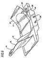
- FIG. 1 shows a simplified version of the resuscitation device 1 .
- the mechanisms used for compressing the chest includes compression assembly 2 which includes a chest compression belt 3 with buckles 4L and 4R, a friction liner 5, a support board 6 and a motor driven spool assembly 7.
- the support board 6 is placed under a cardiac arrest victim, and the compression belt 3 and friction liner 5 are wrapped around the victim's chest.
- the chest compression belt having a left side 3L and a right side 3R, is buckled over the victims chest by latching the buckles 4L and 4R together. In this configuration, the friction liner 5 will fit between the chest compression belt 3 and the victim and any clothes worn by the victim.
- the compression belt may be made of any strong material, and sail cloth has proven adequate for use.
- the compression belt may also be referred to as a vest, corset, girdle, strap or band.
- the friction liner may be made of Teflon®, Tyvek® or any other low friction material (by low friction, we mean a material that will permit sliding of the compression belt with less friction than expected between the belt and the victims clothing or bare skin).
- the friction liner may be made with any suitable lining material, as its purpose is to protect the victim from rubbing injury caused by the compression belt, and it may also serve to limit frictional forces impeding the compression belt operation.
- the friction liner can be provided in the form of a belt, vest, corset, girdle, strap or band, and may partially or completely encircle the chest.
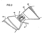
- the front of the compression belt 3, including the buckles 4L and 4R, are configured to provide a broad pressure point over the sternum of the victim. This is illustrated in Figure 2.
- Large openings 8 may be provided to accommodate female breasts and obese male breasts.
- the underside of the buckles 4L and 4R are smooth and broad, to distribute compressive force evenly over a wide area of the chest corresponding to the sternum.
- the point at which the buckle attaches to the chest compression belt may vary considerably, from the front of the chest to the back of the compression assembly, and the openings 8 may be provided in the buckles rather than the belt itself.
- Figure 3 shows a detail of the buckles 4 used to fasten the compression belt about the chest of the victim.
- the buckle may be of any type, and preferably includes a latch sensing switch 9 operably connected through wire 10 to the motor control system (see Figure 13) to indicate that the device has been buckled about the victims chest and is ready for the initiation of compression cycles.
- the buckles shown in Figure 3 are D-ring shaped buckles with large openings 8 , attached to the compression belt 3. Other fasteners and fastening means may be used.
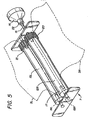
- the chest compression belt 3 is repeatedly tightened about the chest of a victim through the action of one or more tightening spools which make up the spool assembly 7 located within the support board 6.
- the spool assembly illustrated in Figure 4 , includes at least one spool or reel connected to the compression belt 3 at the back of the belt, preferably near the center or saggital line 11 (See Figures 1 and 2) of the compression belt (although it may be located on the front or side of compression belt).
- Figure 4 shows a view of the spool assembly 7 and its attachment to the compression belt 3.
- a spool assembly includes a single drive spool 12 operably connected to the motor 14 through drive shaft 15. The compression belt is secured to the drive spool in any suitable manner.
- a longitudinal slot 16 is provided in the drive spool 12.
- the slot extends radially or chordally through the drive spool and extends axially for a length corresponding to the width of the compression belt, leaving the ends 17 of the drive spool solid for connection to the drive shaft 15 and journal shaft 18.
- the belt is slipped through the slot to created a secure connection between the belt and the drive spool.
- spindles or alignment rollers 19 provide for alignment and low friction feed of the belt onto the roll created by operation of the drive shaft.
- Spools 12L and 12R are aligned in parallel and interconnected by a transmission gear 20 and planetary gear 21 and journaled upon shafts 18L and 18R.
- the drive shaft 15 is attached to spool 12R (or spool 12L) and operably attached to motor 14.
- the motor turns the shaft 15 and spool 12R in a counterclockwise direction to pull the right side of the compression belt 3R to the left and roll onto the spool.
- the transmission gear 20 acts upon the planetary gear 21 to cause clockwise rotation of spool 12L, which in turn pulls and wraps the left side of the compression belt 3L onto the spool 12L.
- the compression belt serves to radially compress the chest through the cooperative action of the belt, board, and buckle, and to disperse the compressive force around the chest.
- the motor is energized to rotate the spools and cause the compression belt to constrict around the chest of a victim.
- a motor such as a battery operated hand drill motor provides adequate chest compression for the purposes of CPR.
- the motor 14 must be attached via a clutch 22 or other such mechanism.
- the motor 14 may be attached to the drive shaft 15 through a torque slipping clutching mechanism which engages the drive shaft until a high torque is achieved (indicating great resistance to further constriction, and thus indicating that the victim's chest has been compressed), and releases automatically upon such high torque, only to re-engage after the belt has been expanded in response to the normal elastic expansion of the victim's chest.
- the motor may be repeatedly energized and de-energized, with the spools spinning freely during periods in which the belt is de-energized, wherein the clutch mechanism 22 will be similar to clutch mechanisms used on electric drills (which engage during operation of the drill but spin freely when the drill is de-energized). While the natural elastic expansion of the chest should make it unnecessary to drive the belt toward a loose condition, positive loosening may be achieved by reversing the motor or reversing the action of the motor through appropriate clutch or gear mechanisms.
- Timing of compressions is regulated through a computer module or a simple relay (windshield wiper style relays), and preferably will conform to standard of the Advanced Cardiac Life Support guidelines or Cardiopulmonary Resuscitation guidelines, or any other medically acceptable resuscitation regime. Current guidelines put forth by the American Heart Association call for 60 to 100 chest compressions per minute.
- the motor is preferably battery powered, with provisions for taking power from any available power source.
- Batteries 23 may be stored within the support board 6. Three volt batteries of convenient size, already available for use with numerous power tools, provide about five minutes of compression per battery, while twelve-volt batteries (1700mA-h per battery) have provided about ten minutes of compression per battery. A thirty minute total battery capacity is desirable (corresponding to the estimated average time between cardiac arrest and transport to the hospital). Accordingly, several batteries may be installed Within the support board and electrically connected to the motor and its controller. The batteries are provided with a trickle charge through a charger socket and charger plugged into 120V AC power when the device is not in use.
- the device may continue to run on AC power to preserve the batteries for later use.
- the unit may also be plugged into an automobile power jack with an appropriate auto adapter, thus providing for use where an automobile is the only source of power, and for extended use in an ambulance.
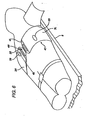
- Figure 6 shows the resuscitation device installed on a cardiac arrest victim.
- the support board 6 is placed under the victim, and the right 3R and left 3L portions of the compression belt are wrapped around the victim's chest and buckled over the front of the chest, indicated by arrow 25.
- the system may be put into operation by manually starting the motors or by automatic initiation given the proper feedback from sensors located on the device, including the buckle latch sensors.
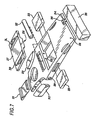
- FIG. 7 illustrates the resuscitation device 1 in a potential commercial embodiment.
- the support board is sized to reach approximately from the lower lumbar region to the shoulders of a victim.
- the compression module 26 is separable from the support board, and includes the compression belt and friction vest stored within the compression module.
- the spool assembly and motor are also stored within the compression module, although the motor may also be installed in the support board.
- the compression module comprises a small support board 27 which fits into the larger system support board 28.
- a compartment 29 for storage of airway management devices (bag masks, oxygen masks, etc.), and a compartment 30 for storage of defibrillation equipment (electrodes and paddles, etc.) are included with the support board.
- a control and communication module 31 may also be incorporated into the support board.
- a small oxygen bottle 32 may be included, along with hoses routed to an accessible point on the board, and any connector desired for connection between the oxygen bottle and devices provided in the airway management compartment.
- Batteries 23 are stored within the support board (the number of the batteries chosen according the desired operating time, and the placement of the batteries dictated by available space). Batteries are operably connected to the motor in the compression module through electrical connectors 33 and appropriate wiring throughout the support board. The batteries can also be operably connected to the defibrillation module and control and communications module. Although long life batteries can be used, rechargeable batteries may be preferred. Accordingly, charging connection 34 on the support board is provided for charging the batteries or operating the device through outside power supplies.
- the device is intended to be stored for long periods of time between uses, and storage holder 35 is provided for this purpose.
- the storage holder can include such necessities as power supply connectors, a power plug, and a charging transformer.
- a removal sensor 36 is included in the support board to sense when the support board is removed from the storage holder (which, as described below, can be used as a condition indicating use of the device, and therefore the need to alert emergency medical personnel).
- the removal sensor can comprise a simple limit switch which senses physical removal of the system, and the limit switch can be used as a power switch or awaken switch which starts initiation of the system.
- the removal sensor can comprise a current sensor on the charging lines which treat cessation of charging current, increase in current draw through the charging system, or motor current as an indication of use.
- the choice of sensor may be made with many practical considerations in mind, such as the desire to avoid treating power outages as indications of use and other such unintended initiations.
- the state in which the device is deemed to be "in use” can be chosen according to the practical considerations, and in most instances it is expected that mere removal of the resuscitation device from the holder will constitute a clear signal someone has determined that a victim requires its use, and that emergency medical personnel should be dispatched to the location of the device.
- the buckle latch shown in Figure 3 can be used as the censor that indicates that the resuscitation device is in use.
- FIG 8 shows the details of the compression module 26.
- the module When not in use, the module is covered with a tear sheet 37 which protects the compression belt from wear.
- the buckles 4 are readily visible under the tear sheet.
- the electrical connectors 38. connect the batteries in the support board with the motor inside the compression module.
- the inside of the compression belt 3 is fitted with penetrating electrodes 39 in the right sternum parasaggital location 40 (See Figure 6) and left rib medial location 41 (See Figure 6) for establishing the electrode contact needed for EKG sensing. These electrodes may be dispensed with in environments where proper placement of the defibrillation electrodes can be assumed due to a high level of training amongst likely bystanders and first responders.
- the friction vest 5 is secured to the compression module above the spool assembly location.
- FIG. 9 shows a detail view of the defibrillation module 30.
- the defibrillation module includes a pair of defibrillation electrodes 42 connected to the batteries through the power connections 43.
- the defibrillation electrodes will be controlled by circuitry housed within the defibrillation module, and may be connected to the control module through the data port 44.
- the defibrillation module is releasably attached to the support board 28 with quick release latches 51. Tear sheet 46 protects the components of the defibrillation module during storage and provides ready access for use.
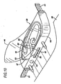
- FIG 10 shows the detail view of the airway management module 29, which includes an oxygen mask 47, a length of tubing 48 and an air fitting 49 connecting the oxygen mask to the oxygen bottle within the support board 28.
- the oxygen mask serves as a blood gas exchange means, supplying oxygen to the lungs for exchange with blood gas such as CO 2 .
- Optional medicine injectors 50 may be operably connected to the masks or hose to provide for automatic injection of ACLS medications into the airway.
- the airway management module is releasably attached to the support board 28 with quick release latches 51. Tear sheet 46 protects the components of the airway management module during storage and provides ready access for use.
- An end-tidal CO 2 monitor 52 can be included in the mask to provide for biological feedback and monitoring of the success of the CPR.
- a skin mounted blood oxygen level monitor 53 can also be mounted on the mask for the same purpose (fingertip blood oxygen sensors may also be used, and supplied in the overall assembly to be readily available).
- the biological data obtained by the sensors is transmitted to the control module via appropriate wiring in the mask and support board.
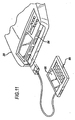
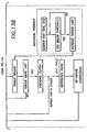
- FIG 11 shows a detail view of the control and communications module.
- the control unit 54 is connected to the compression module, defibrillation module and the airway management module through appropriate wiring through the support board 28.
- the control unit is optionally connected to the communications unit 55.
- the communications unit includes means for communicating the EKG and other measured medical parameters sensed on the board to the screen 56 and via telephone to remote medical personnel.
- the communications unit can include a telephone handset or speaker phone. Because the device is most likely to be used at a location separate from the storage holder, the communications module preferably includes a wireless communication device, such as wireless telephone, radio telephone or cellular, and any necessary telephone base will be installed in the storage holder.
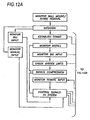
- the communications unit and control unit are set up to operate in the following manner, also illustrated in the block diagram of Figure 12.
- the device may remain mounted in a charging unit for months between use, and will be removed from the charging unit for use.
- a sensor in the control unit senses the removal (through limit switches, magnetic switches, or motion sensors, current sensors in the charging system, or otherwise) and initiates the system, checking functions, energizing a display unit and accomplishing other typical warm-up functions.
- the system initiates a telephone communication with a medical facility through the communications unit.
- the communication may use any communication medium, whether it be standard telephone lines; cellular telephone system, paging system or radio transmitter.
- the system may be set up to initiate communications with central medical facility, such as a: local 911 emergency system, a nearby hospital or ambulance service, or a central facility staffed with medical personnel trained specifically on the remote use of the device (all generally referred to as medical personnel).
- central medical facility such as a: local 911 emergency system, a nearby hospital or ambulance service, or a central facility staffed with medical personnel trained specifically on the remote use of the device (all generally referred to as medical personnel).
- the communications unit informs medical personnel of the location or identification of the device (which may be stored in computer memory in the communications unit, or determined through GPS or other such system), and this information can be used to dispatch an emergency medical team to the location of the device.
- the removal sensor may comprise a limit switch
- the communications module may comprise a simple telephone unit installed in the storage holder together with a tape recorded message, where the operation of the relay in response to removal of the resuscitation device includes initiation of the telephone call to 911 and playback of an alert message providing alert information such as the location of the board.
- the communications unit may also be provided with an alert button which may be operated by a bystander regardless of the use of the board to summon an emergency team to the location regardless of the condition of the resuscitation device.
- sensing electrodes can be included on the inner surface of the compression belt.
- the system monitors the installation of the belt through signals provided by the latching sensors in the buckle.
- the system monitors biological input, which can comprise monitoring of EKG signals from the EKG electrode patches of the defibrillation module, monitoring EKG signals measured by the belt mounted electrodes, monitoring signals from an end-tidal CO 2 monitor from the airway management module, and any other biological signal sensor incorporated into the device.
- the system can also monitor or respond to manually inputted instructions from the control unit, in order to provide on-site emergency medical personnel with control of the device when they arrive on scene.
- the system transmits all available biological information, including EKG: signals, blood pressure, end-tidal CO 2 and any other monitored biological parameter to the remote medical facility, and it can also transmit information regarding the configuration of the device, including battery life, system operating limit settings (i.e., whether the system is set for automatic operation, permissive operation, or disabled in any function) so that medical personnel can ensure that the appropriate configuration is in effect.
- Communication with the medical facility will allow emergency medical personnel to diagnose the condition of the patient and, through signals sent from the medical personnel to the communications unit, permit, initiate or prohibit certain additional therapeutic ACLS actions.
- the medical personnel can send a signal to the communications unit which acts upon the control unit to permit manual operation of the defibrillation electrodes by the bystander.
- the system also provides for application of a defibrillation shock via remote signal from the medical personnel.
- the device can incorporate an expert system such as the Automatic External Defibrillator.
- the medical personnel can also communicate other actions and ensure that certain acts are undertaken by the bystander through the communication system.
- the medical personnel may communicate verbally with the bystander to ascertain the cause of the cardiac arrest, the proper placement of the oxygen mask, appropriate clearing of the airway, and other information.
- the airway management module is provided with medication such as epinephrine, lidocaine, bretylium or other drugs called for in the ACLS guidelines (or newly proposed drugs such as T3)
- the medical personnel can instruct bystanders to inject the appropriate medication through the airway.
- automatic injectors such as those described in Kramer, Interactive External Defibrillation and Drug Injection System, U.S. Patent 5,405,362 (Apr.
- the medical personnel can instruct bystanders to inject appropriate medication through these injectors.
- the injectors are provided with means for automatic operation based on measured EKG signals, blood pressure and end-tidal CO 2
- the medical personnel can send signals to the system to initiate injection by remote control of the medical personnel, permit injection by local control as determined by the expert system, permit injection by bystanders, or prohibit injection by the system or bystanders.
- the system can be initially set up to forbid any injection.
- Medical personnel having diagnosed ventricular fibrillation through the information provided by the communications unit, can send an appropriate signal to permit or initiate injection of epinephrine, and also send a signal to prohibit injection of atropine until called for under the ACLS guidelines.
- a newly proposed drug T3 can be administered through the airway, into the lungs, as a therapy for cardiac arrest. Controlled injection into the airway can be initiated or prohibited in the same manner.
- all actions in the ACLS including compression, defibrillation, drug injection can be accomplished through the system under the guidance of medical personnel from a remote location, or they may be accomplished through expert systems installed in the control module.
- Each of these functions is incorporated into a system that automatically initiates communication with medical personnel and informs medical personnel of the location of the device so that emergency medical personnel may be dispatched to the location.
- the repeated compression will be initiated upon buckling of the compression belt (automatically) or a switch can be provided for the bystander to initiate compression.
- the system will continue compression cycles, until de-activated, according the motor control block diagram of Figure 13.
- the control unit Upon initiation of the system, the control unit will monitor installation of the belt via appropriate sensors in the buckles or through other sensors.
- the motor control 57 receives the initiate compression-signal from the control unit, the motor is started.
- the motor is preferably run continuously, rather than stopped and started, to avoid repeated application of startup current and thus conserve battery power.
- the clutch is up to speed, .. the clutch, .is engaged. As a baseline, the clutch is engaged every second for one-half second.
- the motor controller includes a torque sensor (sensing current supply to the motor, for example), and monitors the torque or load on the motor. A threshold is established above which further compression is not desired or useful, and if this occurs during the half second of clutch engagement, then the clutch is disengaged and the cycle continues.
- the system can monitor the effectiveness of the compression stroke by monitoring the CO 2 content of the victim's exhalant.
- the control system increases the torque limit until the CO 2 levels are acceptable (or until the maximum torque of the motor is achieved.)
- the cycle time and period, number of cycles between respiration pauses, and the torque limit can be set according to current guidelines, and can also be varied by the remote medical personnel via the remote control capabilities of the control unit.
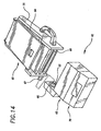
- FIG 14 shows an overview of the resuscitation device 61.
- the major components are provided in modular form, and include the motor box 62, the belt cartridge 63 and the belt 64.
- the motor box exterior includes a sprocket 65 in a drive wheel 66 which releasable mates with the receiving rod 67 on the cartridge.
- the cartridge houses the belt which will wrap around the chest of the patient.
- the cartridge also includes the spool 68 which is turned by the receiving rod. The spool takes up the midpoint of the belt to drive the compression cycles.
- a computer control system 70 may be included as shown in an enclosure mounted on the motor box.
- FIG 15 shows a more detailed view of the cartridge, including the internal mechanisms of the belt cartridge 63.
- the outer body of the cartridge provides for protection of the belt during storage, and includes a back plate 71 with a left panel 71L and a right panel 71R (relative to the patient during use).
- the right plate can be folded over the left plate for storage and transport. Both panels are covered with a sheet 72 of low friction material such as PTFE (Teflon®) to reduce friction when the belt slides over the panel during operation.
- the cartridge Under the left panel, the cartridge has a housing 73 which houses the middle portion of the belt, the spool 68 and the spindle 75 (See Figure 16).
- the lateral side 74 of the cartridge (corresponding to the anatomic position when in use on a patient) houses the drive spool 68, with its drive rod 67 which engages the drive wheel 66 (See Figure 14) of the motor box.
- the cartridge also houses the guide spindle 75 for directing the belt toward the drive spool 68.
- the guide spindle is located near the center of the cartridge (corresponding to the medial line of the patient when in use), so that it is located near the spine when the device is in use.
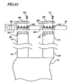
- Figure 25 illustrates the configuration of the motor and clutch within the motor box.
- the exterior of the motor box includes a housing 101 , and a computer module. 70 with a convenient display screen 102 for display of any parameters measured by the system.
- the motor 103 is a typically small battery operated motor which can exert the required belt tensioning torque.
- the motor shaft 104 is lined up directly to the brake 105 which includes reducing gears and a cam brake to control free spinning of the motor when the motor is not energized (or when a reverse load is applied to the gearbox output shaft).
- the gearbox output rotor 106 connects to a wheel 107 and chain 108 which connects to the input wheel 109, and thereby to the transmission rotor 110 of the clutch 111.
- the clutch 111 controls whether the input wheel 109 engages the output wheel 112, and whether rotary input to the input wheel is transmitted to the output wheel.
- the secondary brake 113 which we refer to as the secondary brake, provides for control of the system in some embodiments, as explained below in reference to Figure 32.
- the output wheel 112 is connected to the drive wheel 66 via the chain 114 and drive wheel 66 and receiving rod 67 (the drive rod is on the cartridge).
- the drive wheel 66 has receiving socket 65 which is sized and shaped to mate and engage with the drive rod 67 (simple hexagonal or octagonal sprocket which matches the drive rod is sufficient).
- wrap spring brake (a MAC 45 sold by Warner Electric) for the cam brake in the system
- any form of brake may be employed.
- the wrap spring brake has the advantage of allowing free rotation of the shaft when de-energized, and holds only when energized.
- the wrap spring brake may be operated independent of the motor. While we use chains to transmit power through the system, belts, gears or other mechanisms may be employed.
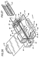
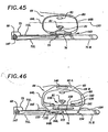
- Figure 26 illustrates the configuration of the motor and clutch within the motor box.
- the exterior of the motor box includes a housing 101 which holds the motor 103, which is a typical small battery operated motor which can exert the required belt tensioning torque.
- the motor shaft 104 is lined up directly to the brake 105 which includes reducing gears and a cam.
- the gearbox output rotor 106 connects the brake to the output wheel 107 and chain 108 which in turn connects directly to the drive wheel 66 and receiving rod 67.
- the drive spool 68 is contained within the housing 101. At the end of the drive spool opposite the drive wheel, the brake 115 is directly connected to the drive spool.
- the belt 64 is threaded through the drive spool slot 69.
- the shield 117 with the long aperture 118 is fastened to the housing so that the aperture lies over the drive spool, allowing the belt to pass through the aperture into the drive spool slot, and return out of the housing.
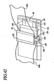
- a push plate 130 Under the housing, slidably disposed within a channel in the bottom of the housing, a push plate 130 is positioned so that it can slide back and forth relative to the housing.
- the belt right portion 64R is fitted with a pocket 131 which catches or mates with the right tip 132 of the push plate.
- the right tip of the push plate is sized and dimensioned to fit within the pocket.
- the belt can be slipped onto the push plate, and with the handle 133 on the left end of the push plate, the push plate together with the right belt portion can be pushed under a patient.
- the belt includes the encoder scale 96, which can be read with an encoder scanner mounted on or within the housing.
- the belt right portion is slipped under the patient by fastening it to the push plate and sliding the push plate under the patient.
- the motor box can then be positioned as desired around the patient (the belt will slip through the drive spool slot to allow adjustment).
- the belt right portion can then be connected to the belt left portion so that the fastened belt surrounds the patient's chest.
- the motor is mounted in side-by-side relationship with the clutch and with the drive spool.
- the motor may be located to the side of the patient, and need not be placed under the patient, or in interfering position with the shoulders or hips. This also allows a more compact storage arrangement of the device, vis-à-vis an in-line connection between the motor and the spool.
- a battery is placed within the box or attached to the box as space allows.
- the shield 117 may also include two lengthwise apertures 134 separated by a short distance. With this embodiment of the shield, one side of the belt passes through one aperture and into the drive spool slot, and the other side of the belt exits from the drive spool slot outwardly through the other aperture in the shield.
- the shield as shown, has an arcuate transverse cross section (relative to the body on which it is installed). This arcuate shape permits the motor box to lay on the floor during use while a sufficient width of shield extends between the box and the belt.
- the shield can be made of plastic, polyethylene, PTFE, or other tough material which allows the belt to slide easily.
- the motor box may, however, be placed anywhere around the chest of the patient.
- a computer module which acts as the system controller is placed within the box, or attached to the box, and is operably connected to the motor, the cam brake, clutch, encoder and other operating parts, as well as biological and physical parameter sensors included in the overall system (blood pressure, blood oxygen, end tidal CO 2 , body weight, chest circumference, etc. are parameters that can be measured by the system and incorporated into the control system for adjusting compression rates and torque thresholds, or belt pay-out and slack limits).
- the computer module can also be programmed to handle various ancillary tasks such as display and remote communications, sensor monitoring and feedback monitoring, as illustrated in our U.S. patent 6,142,962 .
- the computer is programmed (with software or firmware or otherwise) and operated to repeatedly turn the motor and release the clutch to roll the compression belt onto the drive spool (thereby compressing the chest of the patient) and release the drive spool to allow the belt to unroll (thereby allowing the belt and the chest of the patient to expand), and hold the drive spool in a locked or braked condition during periods of each cycle.
- the computer is programmed to monitor input from various sensors, such as the torque sensor or belt encoders, and adjust operation of the system in response to these sensed parameters by, for example, halting a compression stroke or slipping the clutch (or brake) in response to torque limit or belt travel limits.
- the operation of the motor box components may be coordinated to provide for a squeeze and hold compression method which prolongs periods of high intrathoracic pressure.
- the system may be operated in a squeeze and quick release method for more rapid compression cycles and better waveform and flow characteristics in certain situations.
- the operation of the motor box components may be coordinated to provide for a limited relaxation and compression, to avoid wasting time and battery power to move the belt past compression threshold limits or slack limits.
- the computer is preferably programmed to monitor two or more sensed parameters to determine an upper threshold for belt compression. By monitoring motor torque as measured by a torque sensor and paid out belt length as determined by a belt encoder, the system can limit the belt take-up with redundant limiting parameters. The redundancy provided by applying two limiting parameters to the system avoids over-compression in the case that a single compression parameter exceed the safe threshold while the system fails to sense and response the threshold by stopping belt take-up.
- An angular optical encoder may be placed on any rotating part of the system to provide feedback to a motor controller relating to the condition of the compression belt.
- the encoder system may be an optical scale coupled to an optical scanner, a magnetic or inductive scale coupled to a magnetic or inductive encoder, a rotating potentiometer, or any one of the several encoder systems available.
- the encoder 116 for example, is mounted on the secondary brake 113 (in Figure 25), and provides an indication of the motor shaft motion to a system controller.
- An encoder may also be placed on the drive socket 65 or drive wheel 66, the motor 103 and/or motor shaft 104.
- the system includes a torque sensor (sensing current supply to the motor, for example, or directly sensing torque exerted on the drive spool), and monitors the torque or load on the motor, thereby providing an indication of the force applied to the body. For either or both parameters, a threshold is established, above which further compression is not desired or useful, and if this occurs during the compression of the chest, then the clutch is disengaged.
- the belt encoder is used by the control system to track the take-up of the belt, and to limit the length of belt which is spooled upon the drive belt.
- the drive spool has a small diameter such that several rotations of the drive spool are possible (and generally necessary) to effect resuscitative compression.
- the drive spool diameter is preferably in the range of 0.5 to 2.5 cm.
- rotation of a 2.5 cm diameter spool through 1.5 revolution will be required to effect a nominal change in belt length of 12 cm
- rotation of a 0.5 cm diameter spool through eight revolutions will be required to effect a nominal change in belt length of 12 cm.
- the multiple rotations of the spool help limit motor overrun after detection of a system feedback or physiologic feedback parameter and subsequent system response in stopping the motor, engaging the brake, disengaging the clutch, etc.
- the optimal size of the shaft, and all the shafts in the system will vary with the choice of other components, and the angular encoders used in the system may be calibrated according to the particular geometry effective at the shaft to which they are attached.
- the control system In order to control the amount of thoracic compression (change in circumference) for the cardiac compression device using the encoder, the control system must establish a baseline or zero point for belt take-up. When the belt is tight to the point where any slack has been taken up, the motor will require more current to continue to turn under the load of compressing the chest. This, the expected rapid increase in motor current draw (motor threshold current draw), is measured through a torque sensor, (an Amp meter, a voltage divider circuit or the like). This spike in current or voltage is taken as the signal that the belt has been drawn tightly upon the patient and the paid out belt length is an appropriate starting point. The encoder measurement at this point is zeroed within the system (that is, taken as the starting point for belt take-up).
- the encoder then provides information used by the system to determine the change in length of the belt from this pre-tightened or "pre-tensioned" position.
- the ability to monitor and control the change in length allows the controller to control the amount of pressure exerted on the patient and the change in volume of the patient by limiting the length of belt take-up during a compression cycle.
- the voltage applied to the motor may be limited during the pre-tensioning, thereby slowing the motor, increasing the torque of the motor, and leading to the higher, more easily recognized current spike or current increase upon meeting the resistance of the body.
- the rate of belt take up can be monitored through the position encoders illustrated in the several embodiments, either reading the length of deployed or spooled belt from the belt encoder or reading the position of one of the rotating components (which will be related to belt length by a simple multiple) .
- the rate of belt' length change ( ⁇ l/ ⁇ t) may be monitored and analyzed for abrupt changes or a decrease below a certain rate, which will vary with the particular drive train used.
- the expected length of belt take-up for optimum compression is 2,54 - 15,24 cm (1 to 6 inches).
- six inches of travel on a thin individual may create a excessive change in thoracic circumference and present the risk of injury from the device.
- the system determines the necessary change in belt length required by measuring or using the amount of belt travel required to become taut. Knowing the initial length of the belt and subtracting off the amount required to become taut will provide a measure of the patient's size (chest circumference). The system then relies on predetermined limits or thresholds to the allowable change in circumference for each patient on which it is installed, which can be used to limit the change in volume and pressure applied to the patient.
- the threshold may change with the initial circumference of the patient so that a smaller patient will deceive less of a change in circumference as compared to a larger patient (or vice versa, should experience prove that optimal compression extent of compression is inversely related to chest size).
- the encoder provides constant feedback as to the state of travel and thus the circumference of the patient at any given time.
- the system controller ends the compression stroke and continues into the next period of hold or release as required by the compression/decompression regimen programmed into the controller.
- the encoder also enables the system to limit the release of the belt so that it does not fully release. This release point can be determined by the zero point established on the pre-tightening first take-up, or by taking a percentage of the initial circumference or a sliding scale triggered by the initial circumference of the patient.
- the belt could also be buckled so that it remains tight against the patient. Requiring the operator to tighten the belt provides for a method to determine the initial circumference of the patient. Again encoders can determine the amount of belt travel and thus can be used to monitor and limit the amount of change in the circumference of the patient given the initial circumference.
- Typical CPR compression is accomplished at 60 to 80 cycles per minute, with the cycles constituting mere compression followed by complete release of compressive force. This is the case for manual CPR as well as for known mechanical and pneumatic chest compression devices.
- compression cycles in the range of 20 to 70 cpm have been effective, and the system may be operated as high as 120 cpm or more, This type of compression cycle can be accomplished with the motor box with motor and clutch operation as indicated in Figure 28.
- the motor is always on, and the clutch cycles between engagement (on) and release (off).
- the system pauses for several time periods to allow a brief period (several seconds) to provide a respiration pause, during which operators may provide ventilation or artificial respiration to the patient, or otherwise cause oxygenated air to flow into the patient's lungs.
- the brakes illustrated in Figure 25, are not used in this embodiment, though they may be installed.
- the length of the clutch engagement period is controlled in the range of 0 to 2000 msec, and the time between periods of clutch engagement is controlled in the range of 0 to 2000 msec (which, of course, is dictated by medical considerations and may change as more is learned about the optimal rate of compression).
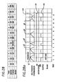
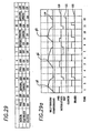
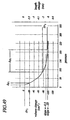
- the timing chart of Figure 28a illustrates the intrathoracic pressure changes caused by the compression belt when operated according to the timing diagram of Figure 28.
- the chest compression is indicated by the status line 119.
- the motor is always on, as indicated by motor status line 120.
- the clutch is engaged or "on” according to the square wave clutch status line 121 in the lower portion of the diagram. Each time the clutch engages, the belt is tightened around the patient's chest, resulting in a high pressure spike in belt tension and intrathoracic pressure as indicated by the compression status line 119.
- Pulses p1, p2, p3, p4 and p5 are all similar in amplitude and duration, with the exception of pulse p3. Pulse p3 is limited in duration in this example to show how the torque limit feedback operates to prevent excessive belt compression.
- Torque limit may be replaced by belt travel or other parameter as the limiting parameter.
- Pulse p3 is shown rapidly reaching the torque limit set on the motor.
- the clutch disengages to prevent injury to the patient and excessive drain on the battery (excessive compression is unlikely to lead to additional blood flow, but will certainly drain the.batteries quickly).
- belt tension and intra-thoracic pressure drop quickly, and the intra-thoracic pressure is increased for only a small portion of cycle.
- the system returns.to the pattern of repeated compressions.
- Pulse p4 ' occurs at the next scheduled compression period T7, after which the respiration pause period spanning T8, T9, and T10 is created by maintaining the clutch in the disengaged condition.
- pulse p5 represents the start of the next set of compressions. The system repeatedly performs sets of compressions followed by respiration pauses until interrupted by the operator.
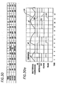
- Figure 29 illustrates the timing of the motor, clutch and cam brake in a system that allows the belt compression to be reversed by reversing the motor. It also provides for compression hold periods to enhance the hemodynamic effect of the compression periods, and relaxation holds to limit the belt pay-out in the relaxation period to the point where the belt is still taut on the chest and not excessively loose.
- the motor operates first in the forward direction to tighten the compression belt, then it is turned off for a brief period, then operates in the reverse direction and turns off, and continues to operate through cycles of forward, off, reverse, off, and so on.
- the cam brake is operating to lock the motor shaft in place, thereby locking the drive spool in place and preventing movement of the compression belt.
- Brake status line 122 indicates the status of the brake 105.
- the motor tightens the compression belt up to the threshold or time limit, the motor turns off and the cam brake engages to prevent the compression belt from loosening. This effectively prevents relaxation of the patient's chest, maintaining a higher intrathoracic pressure during hold periods T2, T6 and T10.
- the motor is reversed and the cam brake is disengaged, allowing the system to drive the belt to a looser length and allowing the patient's chest to relax.
- the cam brake is energized to stop the spool and hold the belt at the pretightened length.
- the clutch is engaged at all times (the clutch may be omitted altogether if no other compression regimen is desired in the system). (This embodiment may incorporate two motors operating in different directions, connecting to the spool through clutches.)
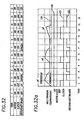
- Figure 29a illustrates the intrathoracic pressure changes caused by the compression belt when operated according to the timing diagram of Figure 29.
- the clutch if any, is always on as indicated by clutch status line 121.
- the cam brake is engaged or "on" according to the brake status line 122, which includes the square wave in the lower portion of the diagram.
- the motor is on, off, or reversed according to motor state line 120. Each time the motor is turned on in the forward direction, the belt is tightened around the patient's chest, resulting in a high pressure spike in belt tension and intrathoracic pressure as shown in the pressure plot line 119. Each time the high threshold limit is sensed by the system, the motor is de-energized, and the cam brake engages to prevent further belt movement.
- Pulse p3 rapidly reaches the torque limit set on the motor (or the take-up limit set on the belt), and the motor stops and the cam brake engages to prevent injury to the patient and excessive drain on the battery. Note that after motor stop and cam brake engagement under pulse p3, belt tension and intra-thoracic pressure are maintained for the same period as all other pulses, and the intra-thoracic pressure is decreased only slightly, if at all, during the high pressure hold period. After pulse, p3; a respiration pause may be initiated in which the belt tension is permitted to go completely slack.
- Figure 30 illustrates the timing of the motor, clutch and cam brake in a system that allows the belt compression to completely relax during each cycle.
- the motor operates only in the forward direction to tighten the compression belt, then is turned off for a brief period, and continues to operate through on and off cycles.
- the motor is on and the clutch is engaged, tightening the compression belt about the patient.
- the motor is turned off and the cam brake is energized (with the clutch still engaged) to lock the compression belt in the tightened position.
- the clutch is disengaged to allow the belt to relax and expand with the natural relaxation of the patient's chest.
- the motor is energized to come up to speed, while the clutch is disengaged and the cam brake is off.
- the motor comes up to speed with no effect on the compression belt in this time period.
- the cycle repeats itself.
- the motor tightens the compression belt up to the threshold or time limit
- the motor turns off and the cam brake engages to prevent the compression belt from loosening. This effectively prevents relaxation of the patient's chest, maintaining a higher intrathoracic pressure.
- the clutch is disengaged, allowing the chest to relax and allowing the motor to come up to speed before coming under load. This provides much more rapid belt compression, leading to a sharper increase in intrathoracic pressure.
- Figure 30a illustrates the intrathoracic pressure changes caused by the compression belt when operated according to the timing table of Figure 30.
- the clutch is turned on only after the motor has come up to speed, according to the clutch status line 121 and motor status line 120, which shows that the motor is energized for two time periods before clutch engagement.
- the cam brake is engaged or "on" according to the brake status line 122 in the lower portion of the diagram.
- the clutch is engaged, the belt is tightened around the patient's chest, resulting in a sharply increasing high pressure spike in belt tension and intrathoracic pressure as shown in the pressure plot .; line 119.
- the cam brake engages and clutch remains engaged to prevent further belt movement, and the clutch prevents relaxation.
- Pulse p2 rapidly reaches the torque limit set on the motor, and the motor stops and the cam brake engages to prevent injury to the patient and excessive drain on the battery. Note that after motor stop and cam brake engagement under pulse p2, belt tension and intra-thoracic pressure are maintained for the same period as all other pulses, and the intrathoracic pressure is decreased only slightly during the hold period.
- the operation of the system according to Figure 30a is controlled to limit belt pressure to a threshold measured by high motor torque (or, correspondingly, belt strain or belt length).
- Figure 31 illustrates the timing of the motor, clutch and cam brake in a system that does not allow the belt compression to completely relax during each cycle. Instead, the system limits belt relaxation to a low threshold of motor torque, belt strain, or belt length.
- the motor operates only in the forward direction to tighten the compression belt, then is fumed off for a brief period, and continues to operate through on and off cycles.
- T1 the motor is on and the clutch is engaged, tightening the compression belt about the patient.
- T2 the motor is turned off and the cam brake is energized (with the clutch still engaged) to lock the compression belt in the tightened position.
- the clutch In the next time period T3, the clutch is disengaged to allow the belt to relax and expand with the natural relaxation of the patient's chest.
- the drive spool will rotate to pay out the length of belt necessary to accommodate relaxation of the patient's chest.
- the clutch In the next period T4, while the motor is still off, the clutch is engaged (with the cam brake still on) to prevent the belt from becoming completely slack.
- the motor starts and the cam brake is turned off and another compression cycle begins.
- Figure 31a illustrates the intrathoracic pressure and belt strain that corresponds to the operation of the system according to Figure 31.
- Motor status line 120 and the brake status line 122 indicate that when the motor tightens the compression belt up to the high torque threshold or time limit, the motor turns off and the cam brake engages to prevent the compression belt from loosening.
- the high pressure attained during uptake of the belt is maintained during the hold period starting at T2.
- the belt is loosened at T3 by release of the clutch (which uncouples the cam brake)
- the intrathoracic pressure drops as indicated by the pressure line 119.
- the clutch engages (and re-couples the cam brake) to hold the belt at some minimum level of belt pressure.
- Figure 32 shows a timing table for use in combination with a system that uses the motor, clutch, and secondary brake 113 or a brake on drive wheel or the drive spool itself.
- the brake 105 is not used in this embodiment of the system (though it may be installed in the motor box).
- the motor status line 120 indicates, the motor operates only in the forward direction to tighten the compression belt, and is always on.
- T1 the motor is on and the clutch is engaged, tightening the compression belt about the patient.
- the motor is on but the clutch is disengaged and the brake is energized to lock the compression belt in the tightened position.
- the clutch is disengaged and the brake is off to allow the belt to relax and expand with the natural relaxation of the patient's chest.
- the drive spool will rotate to pay out the length of belt necessary to accommodate relaxation of the patient's chest.
- the clutch is disengaged, but energizing the secondary brake is effective to lock the belt prevent the belt from becoming completely slack (in contrast to the systems described above, the operation of the secondary brake is effective when the clutch is disengaged because the secondary brake is downstream of the clutch) .
- the motor starts and the secondary brake is turned off, the clutch is engaged and another compression cycle begins.
- the clutch is engaged for time periods T11 and T12 while the torque threshold limit is not achieved by the system. This provides an overshoot compression period, which can be interposed amongst the torque limited compression periods.
- Figure 32a illustrates the intrathoracic pressure and belt strain that correspond to the operation of the system according to Figure 32.
- Motor status line 120 and the brake status line 122 indicate that when the motor tightens the compression belt up to the high torque threshold or time limit, the secondary brake engages (according to secondary brake status line 122) and the clutch disengages to prevent the compression belt from loosening.
- the high pressure attained during uptake of the belt is maintained during the hold period starting at T2.
- the intrathoracic pressure drops as indicated by the pressure line.
- the secondary brake engages to hold the belt at some minimum level of belt pressure.
- Figure 33 shows a timing table for use in combination with a system that uses the motor, clutch, and secondary brake 113 or a brake on drive wheel or the drive spool itself.
- the brake 105 is not used in this embodiment of the system (though it may be installed in the motor box) .
- the motor status line 120 indicates, the motor operates only in the forward direction to tighten the compression belt, and is always on.
- T1 and T2 the motor is on and the clutch is engaged, tightening the compression belt about the patient.
- the brake is not energized to hold the belt during the compression periods (T1 and T2) unless the upper threshold is achieved by the system.
- the clutch is disengaged and the brake is off to allow the belt to relax and expand with the natural relaxation of the patient's chest.
- the drive spool will rotate to pay out the length of belt necessary to accommodate relaxation of the patient's chest.
- the belt pays out to the zero point, so the system energizes the secondary brake.
- the motor remains on ; the clutch is disengaged, and the secondary brake is effective to lock the belt to prevent the belt from becoming completely slack (in contrast to the systems using the cam brake, the operation of the secondary brake is effective when the clutch is disengaged because the secondary brake is downstream of the clutch).
- the motor continues and the secondary brake is turned off, the clutch is engaged and another compression cycle begins.
- the system achieves the high threshold during time period T6, at peak p2, and causes the clutch to release and the secondary brake to engage, thereby holding the belt tight in the high compression state for the remainder of the compression period (T5 and T6).
- the brake is momentarily disengaged to allow the belt to expand to the low threshold or zero point, and the brake is engaged again to hold the belt at the low threshold point.
- Pulse p3 is created with another compression period in which brake is released and the clutch is engaged in T9 and T10, until the threshold is reached, whereupon the clutch disengages and the brake engages to finish the compression period with the belt held in the high compression state.
- time periods T11 and T12 the clutch is disengaged and the brake is released to allow the chest to relax completely. This provides for a respiration pause in which the patient may be ventilated.
- Figure 33a illustrates the intrathoracic pressure and belt strain that corresponds to the operation of the system according to Figure 33.
- the motor status line 120 and the secondary brake status line 122 indicate that the motor tightens the compression belt up to the end of the compression period (the system will not initiate a hold below the upper threshold).
- the intrathoracic pressure drops as indicated by the pressure line.
- the secondary brake engages to hold the belt at some minimum level of belt pressure. This effectively prevents total relaxation of the patient's chest, maintaining a slightly elevated intrathoracic pressure even between compression cycles. A period of low level compression is created within the cycle.
- Motor status line 120 and the brake status line 122 indicate that when the: motor tightens the compression belt up to the high torque threshold or time limit, the secondary brake engages and the clutch disengages to prevent the compression belt from loosening.
- the high pressure attained during uptake of the belt is maintained during the hold period starting at T6.
- the intrathoracic pressure drops as indicated by the pressure line.
- the secondary brake engages to hold the belt at the lower threshold.
- the upper threshold is again achieved, so and the clutch is disengaged and the brake is engaged at time T10 to initiate the high compression hold.
- Figure 34 shows a timing table for use in combination with a system that uses the motor, clutch, and secondary brake 113 or a brake on drive wheel or the drive spool itself.
- the brake 105 is not used in this embodiment of the system (though it may be installed in the motor box).
- the motor status line 120 indicates, the motor operates only in the forward direction to tighten the compression belt, and is always on.
- T1 the motor is on and the clutch is engaged, tightening the compression belt about the patient.
- the motor is on, the clutch is disengaged in response to the sensed threshold, and the brake 113 is enabled and energized to lock the compression belt in the tightened position only if the upper threshold is sensed during the compression period.
- the clutch is disengaged and the brake is off to allow the belt to relax and expand with the natural relaxation of the patient' s chest.
- the drive spool will rotate to pay out the length of belt necessary to accommodate relaxation of the patient's chest.
- the clutch is disengaged, but energizing the secondary brake is effective to lock the belt preventing the belt from becoming completely slack (in contrast to the systems described above, the operation of the secondary brake is effective when the clutch is disengaged because the secondary brake is downstream of the clutch).
- the motor continues running and the secondary brake is turned off, the clutch is engaged and another compression cycle begins.
- the clutch is on in time period T9.
- the clutch remains engaged and the brake is enabled but not energized in.time period T10.
- the clutch and brake are controlled in response to the threshold, meaning that the system controller is waiting until the high threshold is sensed before switching the system to the hold configuration in which the clutch is released and the brake is energized.
- the high threshold is not achieved during compression periods T9 and T10, so the system does not initiate a hold.
- Figure 34a illustrates the intrathoracic pressure and belt strain that correspond to the operation of the system according to Figure 34.
- Motor status line 120 and the secondary brake status line 122 indicate that when the motor tightens the compression belt up to the high torque threshold or time limit, the clutch disengages and the secondary brake engages to prevent the compression belt from loosening.
- the period of compression comprises a period of active compressing of the chest followed by a period of static compression.
- the secondary brake engages to hold the belt at some minimum level of belt pressure. This effectively prevents total relaxation of the patient's chest maintaining a slightly elevated intrathoracic pressure between compression cycles. A period of low level compression is created within the cycle. Note that in cycles where the upper threshold is not achieved, the compression period does not include a static compression (hold) period, and the clutch is engaged for two time periods T9 and T10, and the system eventually ends the active compression based on the time limit set by the system.
- Figure 35 shows a timing table for use in combination with a system that uses the motor, clutch, the cam brake 105 and a secondary brake 113 (or a brake on drive wheel or the spindle itself) . Both brakes are used in this embodiment of the system.
- the motor operates only in the forward direction to tighten the compression belt.
- T1 the motor is on: and the clutch is engaged, tightening the compression belt about the patient.
- T2 the upper threshold is achieved and the motor is turned off in response to the sensed threshold, the clutch is still engaged, and the cam brake is enabled and energized to lock the compression belt in the tightened position (these events happen only if the upper threshold is sensed during the compression period) .
- the belt relaxes and expands with the natural relaxation of the patient's chest.
- the drive spool will rotate to pay out the length of belt necessary to accommodate relaxation of the patient's chest.
- the clutch remains disengaged, but energizing the secondary brake is effective to lock the belt to prevent the belt from becoming completely slack.
- the secondary brake is turned off, the clutch is engaged and another compression cycle begins (the motor has been energized earlier, in time period T3 or T4, to bring it up to speed).
- the clutch is on in time period T9.
- the clutch remains engaged and the cam brake is enabled but not energized in time period T10.
- the clutch and cam brake are controlled in response to the threshold, meaning that the system controller is waiting until the high threshold is sensed before switching the system to the hold configuration in which the clutch is released and the cam brake is energized.
- the high threshold is not achieved during the compression periods T9 and T10, so the system does not initiate a hold.
- the cam brake serves to hold the belt in the upper threshold length
- the secondary brake serves to hold the belt in the lower threshold length.
- Figure 35a illustrates the intrathoracic pressure and belt strain that corresponds to the operation of the system according to Figure 35.
- Motors status line 120 and the cam brake status line 122 indicate that when the motor tightens the compression belt up to the high torque threshold or time limit, the motor turns off and the cam brake engages to prevent the compression belt from loosening (the clutch remains engaged).
- the high pressure attained during uptake of the belt is maintained during the hold period starting at T2.
- the period of compression comprises a period of active compressing of the chest followed by a period of static compression.
- the intrathoracic pressure drops as indicated by the pressure line 119.
- the secondary brake engages to hold the belt at some minimum level of belt pressure, as indicated by the secondary brake status line 123. This effectively prevents total relaxation of the patient's chest, maintaining a slightly elevated intrathoracic pressure even between compression cycles. A period of low level compression is created within the cycle. Note that in cycles where the upper threshold is not achieved, the compression period does not include a static compression (hold) period, and the clutch is engaged for two time periods T9 and T10, and the system eventually ends the active compression based on the time limit set by the system.
- the system operates the clutch and brake to allow relaxation to the lower threshold at point B, and then initiates the low threshold hold period.
- a new compression stroke is initiated at point C, and maintained until the peak compression is reached at point D.
- the actual time spent in the active compression varies depending on how .long it takes the system to achieve the threshold.
- cycle time a. complete period of .. active compression, release and low threshold hold, until the start of the next compression
- the low threshold relaxation period floats accordingly.
- an outer time limit is imposed on each compression period, as illustrated at point G, where the compression is ended before reaching the maximum allowed compression.
- the system clock is reset each time the upper threshold is achieved.
- the preset time limits 135 for low compression hold periods are shifted leftward on the diagram of Figure 36a, to floating time limits 136. This approach can be combined with each of the previous control regimens by resetting the timing whenever those systems reach the upper threshold.
- the arrangement of the motor, cam brake and clutch may be applied to other systems for belt driven chest compressions.
- Lach, Resuscitation Method And Apparatus U.S. Patent 4, 770, 164 (Sep. 13, 1988 ) proposes a hand-cranked belt that fits over the chest and two chocks under the patient's chest. The chocks hold the chest in place while the belt is cranked tight. Torque and belt tightness are limited by a mechanical stop which interferes with the rotation of the large drive roller. The mechanical stop merely limits the tightening roll of the spool, and cannot interfere with the unwinding of the spool.
- a motor is proposed for attachment to the drive rod, and the mate between the motor shaft and the drive roller is a manually operated mechanical interlock referred to as a clutch.
- This "clutch” is a primitive clutch that must be' set by hand before use and cannot be operated during compression cycles. It cannot release the drive roller during a cycle, and it cannot be engaged while the motor is running, or while the device is in operation.
- application of the brake and clutch arrangements described above to a device such as Lach will be necessary to allow that system to be automated, and to accomplish the squeeze and hold compression pattern.
- Lach, Chest Compression Apparatus for Cardiac Arrest, WO/1997/022327 also proposes a compression belt operated by a scissor-like lever system, and proposes driving that system with a motor which reciprocatingly drives the scissor mechanism back and forth to tighten and loosen the belt.
- Lach teaches that failure of full release is detrimental and, suggests that one cycle of compression would not start until full release has occurred.
- This system can also be improved by the application of the clutch and brake systems described above. It appears that these and other belt tensioning means can be improved upon by the brake and clutch system.
- Lach discloses a number of reciprocating actuators for driving the belt, and requires application of force to these actuators.
- the scissor mechanism is operated by applying downward force on the handles of the scissor mechanism, and this downward force is converted into belt tightening force by the actuator.
- the advantages of our clutch and brake system can be obtained with each of the force converters disclosed in Lach.
- the socketed connection between the motor and drive spool can be replaced with a flexible drive shaft connected to any force converter disclosed in Lach.
- Figure 37 illustrates an embodiment of the chest compression device with a sternal bladder.
- the compression belt 3 incorporates an air bladder 140 which, in use, is located on the inner side of the compression vest over the sternum of the patient, and may be of various sizes with a volume of just a few cubic centimeters of air to several hundred cubic centimeters of air, up to about one liter.
- the compression belt in this case is secured to the body with two overlapping areas 141R and 141L of hook and loop fastener (Velcro®) or other fastener, with the air bladder preferably located over the sternum of the patient.
- Velcro® hook and loop fastener
- the bladder itself is also compressed by the belt, and this compression causes an increase in the.pressure in the air bladder.
- a pressure sensor operably connected through a : sensing line 142 to the air bladder 140 senses the pressure in the air bladder and transmits a corresponding signal to the controller. Since a sensing line is used, the pressure transducer may be located off the belt and may be placed inside the control box, and the sensing line must then reach from the bladder (under the belt) to the control box. (The pressure sensor may instead be located within the bladder itself, requiring an electrical power and signal transmission cable 143 extending from the bladder to the control box.)
- the pressure bladder is preferably located on the length of belt on the same side of the patient as the control system (in this case, the left side belt segment 64L) so that the sensing line or electrical cable does not interfere with placement of the belt on the patient.
- the pressure bladder may be located anywhere on the belt, such as below the patient's spine, but as described below placement over the sternum helps control the compressed shape of the thorax.
- Several bladders may be distributed around the thorax to indicate local pressure around the circumference of the thorax.
- bladders may be located on the lateral surface of the chest, between the chest and the compression belt, in parasaggital locations on the front of the chest, between the chest and the compression belt, and in parasaggital locations between the back and the compression belt (or backboard). With several bladders placed around the chest and connected to pressure transducers, the force profile on an test subject or actual patient may be recorded and compared to blood flow, so that the effect of varying the force profile can be determined.
- the controller may incorporate the pressure signal into its control algorithm by limiting the take-up of the belt so as not to exceed 200-300 mmHg in the air bladder (since the pressure in' the air bladder should correspond directly to the pressure exerted on the patients chest) (240 mmHg is currently preferred).
- the pressure signal may also be used to ensure that pressure in the air bladder, and correspondingly pressure exerted on the patient, reaches a minimum effective pressure of about 240 mmHG in each compression.
- the air bladder is filled with a volume of air prior to use, and need not be further inflated during storage or use unless it is prone to leakage.
- the pressure signal may also be used as an indication that the belt has been pre-tensioned, and all slack had been taken.up, whereupon the controller can record an encoder reading which is used as the starting point for determining the amount of belt movement that has occurred during a given compression.
- pressure of 10 to 50 mmHg in the bladder is used as the pre-tensioned point.
- the bladder may filled with any fluid, gel or other medium capable of transmitting pressure to a pressure sensor, and will operate to provide a pressure sensing volume and/or a shape control volume. When filled with air, the bladder will be slightly compressible and have a variable volume, and when filled with fluid such as water, the bladder will be incompressible and have an essentially fixed volume.
- Alternate means for sensing pressure or force applied to the body may be used, including pressure transducers, force transducers and force sensing resistors mounted on the belt between the belt and the patient.
- Figure 42 illustrates an embodiment of the chest compression device with a spinal support plate 150.
- the compression belt left section 64L and right sections 64R are joined in a seam 151 to pull straps 144 as shown in Figure 38, and the pull straps are fixed to the drive spool 68 within the cartridge 63.
- the compression belt right section 64R extends from the pull strap medial end 152 (that is, the end near the medial area of the body, when applied to a patient), under the medially located lower spindle 153 and the slightly lateral upper right spindle 154, under the spinal support platform 150 and further outward to extend under the right flank of the patient when in use.
- the compression belt left section 64L extends from the pull strap medial end 152 (that is, the end near the medial area of the body, when applied to a patient), reversing direction around the slightly lateral upper left spindle 155, under the spinal support platform 150 and further outward to extend under the left flank of the patient when in use.
- the spinal support platform 150 extends inferiorly and superiorly (upward and downward) over the cartridge, and serves to support the patient over the cartridge and away from the underlying area in which the belt runs into the cartridge, thus eliminating a large portion of the frictional load which the belt would otherwise have to overcome during operation.
- the PTFE sheet 72 may be provided on the upper surface of the spinal support platform to reduce friction and rubbing due to chest compression.
- Figures 43 and 44 illustrate the operation of the compression device when fitted with the features described in Figures 37.
- the compression belt 64 is wrapped around the patient's thorax 80.
- the bladder 140 is placed between the patient and the left belt portion 64L over the patient's sternum 82 because the motor box and control box are located on the left side of the patient.
- the connection of the belt to the pull straps is illustrated, with the pull straps 144 connected at their medial end 152 to the left and right belt portions, and connected at their spool end 147 to the drive spool 68 (it can appreciated in this view that the compression belt may be made of a single length of belt:, with the pull straps being secured at its midsection, or may be made of two separate lengths of belt secured at their respective medial ends to the pull straps).
- connection of the pull straps to the drive spool results in a uniform pull length (as illustrated in Figure 44) on each side of the belt, which eliminates the torque on the body resulting from the extra pull length created when spooling two layers of strap or belt over one another, as described in reference to Figures 16 and 17.
- the drive spool rotates through several revolutions, taking up several layers of pull straps, to accomplish the belt tightening in each compression cycle.
- FIGs 43 and 44 Also shown in Figures 43 and 44 is the effect of the fixed bladder on the shape of the thorax after compression.
- the thorax is maintained in a somewhat oval cross section, and is preferentially compressed in the front to back direction (arrow 156).
- anterior-posterior compression or sternal compression in contrast to the circumferential compression described earlier.
- the shape of the compressed torso is urged toward a flat ovoid shape, and away from the rounder, more circular shape of the torso which results without the bladder as shown in Figure 45 (some patients, for unknown reasons, tend to compress more readily from the sides, resulting in the rounder shape in the cross section of the torso).
- the bladder avoids the tendency in some patients to compress into a rounder cross section compressed excessively in the lateral dimension direction (line 157), thus potentially lifting the sternum upwardly.
- the physical presence of the bladder is advantageous in the operation of the device.
- the rounded shape compressions while useful, are believed to have lower efficiency in terms of the correlation between compression of the chest and compression of the heart and thoracic aorta.
- the operation of the spinal support platform 150 can also be seen in Figures 43 and 44.
- the platform extends laterally across the spinal depression 158 which runs up and down the back.
- the width of the spinal support platform is chosen so that, in most patients, it extends laterally to the shoulder blades (scapula) 159 or medial border of the scapula 160 of the patient, or to the protrusion of the trapezius muscle 161 on either side of the spinal depression of the back (area 158).
- the platform thus spans the spinal depression, and extends bilaterally across the spinal depression to the protrusions of the trapezius muscle or the medial border of the shoulder blade.
- the belt sections 64R and 64L pass under the platform through a vertical gap 163 between the platform and the cartridge or backplate, thereby avoiding running directly between the patient's body and the cartridge for a small lateral width extending slightly beyond the width of the platform.
- Figure 46 is modification of the device shown in Figure 42.
- the guide spindles 153 center spindle
- 154 right spindle
- 155 left spindle
- the left and right guide spindles are located farther toward the sides of the patient in this device than they are in Figure 42, where they are essentially located under the spine.
- the guide spindles are located several inches laterally of the spine, and lie under the scapula or trapezius region of the patient. This location alters the force profile of the belt, creating a generally anterior to posterior force on the thorax, rather than a circumferentially uniform force profile.
- the exact location of the guide spindles may be adjusted either further laterally, or medially (back toward the center position immediately under the spine, as in Figure 42) to increase or decrease the balance between anterior to posterior force and circumferential force applied to the typical patient.
- the addition of lateral support plates 164 and 165 on the right and left sides of the body provide support for the patient, and also form, with the spinal support plate 150, the gaps through which the belt passes to extend from the cartridge to the patient.
- sternal displacement is closely related to the spool rotations.
- Apdisplacement empirical ( 0.0739 ⁇ rev . 2 + 1.4389 rev .
- (rev.) is the total number of revolutions of the spool, as measured by an encoder in the system capable of measuring spool rotations, either directly or indirectly ;
- (take-up rev.) is the number of revolutions required to take up any slack in the belt, according to the methods described above-. Either of these equations may be used by the controller of the system to calculate the amount of displacement, either as a back-up to other feed back control methods or as a primary method.
- the controller software keeps track of the take-up revolutions, and the otherwise expected sternal displacement from these revolutions is subtracted from the displacement calculated from the total number of revolutions to provided the actual sternal displacement from a given number of rotations after take-up of slack.
- the displacement information can be used by the system to inform the system as to the patient's initial height, which can then be correlated to a desired sternal displacement (big people need more compression).
- sternal compression of 2,54 - 5,08cm (1 to 2. inches) or twenty percent of sternal height is desired. Either of these sternal displacement goals may be met by calculating the sternal displacement as indicated above.
- an approximation may be made as to the size of the patient, and this information may be used to determined the desired sternal displacement, and/or adjust other thresholds of the system if desired. For example, knowing the initial length of the entire belt, and subtracting the length spooled during take-up, the length of belt deployed about the patient can be calculated.
- Figure 47 shows embodiments of the motor box 62 and the coupling between the motor 103 and the drive spool 68.
- the drive spool and motor are again aligned in a folded, antiparallel relationship, so that the motor lies laterally outside the drive spool relative to the patient when in use.
- the motor output shaft 104 drives reduction gears 168, and the reduction gear output shaft 169 drives a non-reversing coupling 170, and the output shaft. 171 of the non-reversing coupling drives the sprocketed output wheel 112.
- the sprocketed output wheel 112 in turn drives the chain 172 and the sprocketed drive wheel 66 and the drive spool.
- a non-reversing coupling 170 is interposed in the drive train, for example at the output of the reduction gear (as shown) or at the output of the drive spool sprocket.
- the non-reversing coupling may be driven in either clockwise or counterclockwise direction when the input shaft is turned by the drive train inputs upstream from the coupling, so that rotation of the input shaft 169 is possible, and results in rotation of the output shaft 171.
- rotation of the output shaft, driven from the downstream side of the drive train (as might occur during chest expansion) is prohibited by internal mechanisms of the coupling, and thus does not reverse power the input shaft.
- bi-directional no-back couplings may be used, and are referred to as bi-directional no-back couplings or bi-directional reverse locking couplings.
- the bi-directional no-back couplings available from Warner Electric incorporates wrap-down springs and interfering tangs. The coupling can be turned only when torque is applied to the input shaft, which may be driven in either direction, but when there is no torque on the input, the output shaft is effectively locked and cannot be rotated in either direction. Any torque applied to the output shaft is transmitted to the clutch body, and will not be transmitted to the input shaft.
- the bi-directional no-back couplings available from Formsprag Engineering incorporate sprags within the clutch body which interfere with reversing rotation of the output shaft.
- the bi-directional no-back coupling installed in the drive train may be used instead of the clutches and brakes described in relation to Figure 25.
- the braking and clutching action is replaced by the reverse locking function of the coupling.
- Figure 48 the timing of the system operation is greatly simplified. During each compression stroke, the motor is operated in the tightening direction until the desired feedback limit is reached. The motor is then stopped. The upper level hold is achieved automatically by the reverse locking behavior of the coupling. At the end of the hold period, the motor is operated in reverse, in the loosening direction, whereupon the coupling automatically unlocks and permits loosening rotation.
- the motor is stopped, whereupon continued loosening rotation of the drive spool is prohibited by the reverse-locking behavior of the coupling.
- the motor may be stopped in the loosening direction in response to feedback based on belt length (from the belt encoders), the pressure in the air bladder, torque on the motor, or other feedback indicating that the low threshold belt position has been reached. Ventilation pauses in which the belt is completely loosened may be interposed between sets of compressions by driving the motor in the loosening direction well past the low threshold.
- the final position of the belt in the ventilation pause may be determined by from the encoders, from the pressure in the bladder, or other feedback.
- Figure 48 illustrates the intrathoracic pressure and belt strain that corresponds to the operation of the system which uses a non-reversing coupling.
- Motor status line 120 and the non-reversing coupling line 173 indicate that when the motor is operating to tighten the compression belt up to the high torque threshold or time limit, the non-reversing coupling is driven by the motor.
- the non-reversing coupling locks to prevent the compression belt from loosening.
- the coupling locks to prevent reversing without any input from the controller.
- the high pressure attained during uptake of the belt is maintained during the hold period starting at T2.
- the system may be operated with the low threshold in effect, and no upper threshold in effect, or with an upper threshold in effect with no lower threshold in effect.
- reverse operation of the motor refers to operation of the motor in the loosening operation, as compared to forward operation which refers to operation of the motor in the tightening direction.
- reversing refers to reverse-powering the coupling by turning the output shaft to cause rotation of the input shaft.
- the non-reversing coupling will not allow reverse powering, it can rotate in the forward and reverse, clockwise or counterclockwise, and loosening or tightening directions, as those terms are used in reference to the motor.
- pressure feedback control belt length or volume feedback control
- motor torque control it appears from our experience that pressure and thoracic volume are related in such a manner that compression cycles may be controlled with feedback regarding the relationship between the measured volume and the sensed pressure.
- control of the motor, clutch, brake and other components of the drive train may be controlled as a function of the relationship between the force applied to the body and change in the length of the belt.
- the pressure applied to the thorax is measured, as indicated above, by measuring the pressure in the air bladder illustrated in Figure 37, or with pressure transducers, force transducers or other means for sensing force applied to the body Torque sensors operably connected to the belt through by connection at any point in the drive train or by sensing motor current, may also be used to sense the force applied to the body
- Torque sensors operably connected to the belt through by connection at any point in the drive train or by sensing motor current, may also be used to sense the force applied to the body
- the length is measured by scanning the belt encoder or scanning rotary encoders in the drive train, as described above (any other mechanism for measuring belt length may be used).
- the volume is computed using belt length as a proxy for circumference of the chest, and assuming a circular cross section of the chest.
- the change in belt length is measures through an encoder placed in one of several places in the system as described above.
- Figure 49 illustrates the relationship between the change in thoracic volume compression (or change in belt length) versus the thoracic pressure.
- an initial large negative change in volume ⁇ v 1 causes a small change in thoracic pressure ⁇ p 1
- the same volume change ⁇ v 2 near the end of the compression results in a large increase in pressure ⁇ p 2 .
- large changes in pressure are required to produce small changes in volume at the end of the compression. This is an asymptotic curve with a slope approaching zero..
- control system is programmed to monitor inputs corresponding to thoracic volume (deployed belt length or other proxy) and thoracic pressure (bladder pressure or other proxy), and limit motor operation by ending a compression when the ratio of volume change versus pressure change (the slope of the curve in Figure 49) falls below a preset value.
- the preset value is experimentally determined to be in the range of 0.05 to 0.5 cm 2 /mmhg.
- control system is programmed to monitor inputs corresponding to deployed belt length and thoracic pressure (bladder pressure or other proxy), and limit motor operation by ending a compression when the ratio of belt length change versus pressure change (the slope of the curve in Figure 49 falls below a preset value.
Landscapes
- Health & Medical Sciences (AREA)
- Heart & Thoracic Surgery (AREA)
- Cardiology (AREA)
- Life Sciences & Earth Sciences (AREA)
- Public Health (AREA)
- Veterinary Medicine (AREA)
- Animal Behavior & Ethology (AREA)
- General Health & Medical Sciences (AREA)
- Physical Education & Sports Medicine (AREA)
- Emergency Medicine (AREA)
- Pulmonology (AREA)
- Epidemiology (AREA)
- Pain & Pain Management (AREA)
- Rehabilitation Therapy (AREA)
- Nuclear Medicine, Radiotherapy & Molecular Imaging (AREA)
- Biomedical Technology (AREA)
- Engineering & Computer Science (AREA)
- Radiology & Medical Imaging (AREA)
- Percussion Or Vibration Massage (AREA)
- Control Of Transmission Device (AREA)
Priority Applications (2)
| Application Number | Priority Date | Filing Date | Title |
|---|---|---|---|
| EP10182236.9A EP2314269A3 (en) | 2001-05-25 | 2002-05-24 | CPR assist device with pressure bladder feedback |
| EP07115673.1A EP1857086B1 (en) | 2001-05-25 | 2002-05-24 | CPR assist device with pressure bladder feedback |
Applications Claiming Priority (3)
| Application Number | Priority Date | Filing Date | Title |
|---|---|---|---|
| US866377 | 1992-04-09 | ||
| US09/866,377 US6616620B2 (en) | 2001-05-25 | 2001-05-25 | CPR assist device with pressure bladder feedback |
| PCT/US2002/016479 WO2002096343A2 (en) | 2001-05-25 | 2002-05-24 | Cpr assist device with pressure bladder feedback |
Related Child Applications (2)
| Application Number | Title | Priority Date | Filing Date |
|---|---|---|---|
| EP07115673.1A Division EP1857086B1 (en) | 2001-05-25 | 2002-05-24 | CPR assist device with pressure bladder feedback |
| EP10182236.9A Division EP2314269A3 (en) | 2001-05-25 | 2002-05-24 | CPR assist device with pressure bladder feedback |
Publications (3)
| Publication Number | Publication Date |
|---|---|
| EP1401373A2 EP1401373A2 (en) | 2004-03-31 |
| EP1401373A4 EP1401373A4 (en) | 2005-02-02 |
| EP1401373B1 true EP1401373B1 (en) | 2007-09-05 |
Family
ID=25347478
Family Applications (3)
| Application Number | Title | Priority Date | Filing Date |
|---|---|---|---|
| EP02746448A Expired - Lifetime EP1401373B1 (en) | 2001-05-25 | 2002-05-24 | Cpr assist device with pressure bladder feedback |
| EP10182236.9A Withdrawn EP2314269A3 (en) | 2001-05-25 | 2002-05-24 | CPR assist device with pressure bladder feedback |
| EP07115673.1A Expired - Lifetime EP1857086B1 (en) | 2001-05-25 | 2002-05-24 | CPR assist device with pressure bladder feedback |
Family Applications After (2)
| Application Number | Title | Priority Date | Filing Date |
|---|---|---|---|
| EP10182236.9A Withdrawn EP2314269A3 (en) | 2001-05-25 | 2002-05-24 | CPR assist device with pressure bladder feedback |
| EP07115673.1A Expired - Lifetime EP1857086B1 (en) | 2001-05-25 | 2002-05-24 | CPR assist device with pressure bladder feedback |
Country Status (8)
| Country | Link |
|---|---|
| US (7) | US6616620B2 (enExample) |
| EP (3) | EP1401373B1 (enExample) |
| JP (3) | JP2004534574A (enExample) |
| AT (1) | ATE372103T1 (enExample) |
| AU (4) | AU2002316169B2 (enExample) |
| CA (3) | CA2776365C (enExample) |
| DE (1) | DE60222260T2 (enExample) |
| WO (1) | WO2002096343A2 (enExample) |
Families Citing this family (154)
| Publication number | Priority date | Publication date | Assignee | Title |
|---|---|---|---|---|
| US6066106A (en) * | 1998-05-29 | 2000-05-23 | Emergency Medical Systems, Inc. | Modular CPR assist device |
| IL141824A (en) * | 2001-03-05 | 2008-11-03 | Flowmedic Ltd | Portable device for the enhancement of the circulation and for the prevention of stasis related deep vein thrombosis (dvt) |
| US6616620B2 (en) * | 2001-05-25 | 2003-09-09 | Revivant Corporation | CPR assist device with pressure bladder feedback |
| IL160185A0 (en) * | 2004-02-02 | 2004-07-25 | Flowmedic Israel Ltd | A portable device for the enhancement of circulation of blood and lymph flow in a limb |
| US7569021B2 (en) | 2002-03-21 | 2009-08-04 | Jolife Ab | Rigid support structure on two legs for CPR |
| TW528593B (en) * | 2002-05-17 | 2003-04-21 | Jang-Min Yang | Device for monitoring physiological status and method for using the device |
| US6827695B2 (en) * | 2002-10-25 | 2004-12-07 | Revivant Corporation | Method of determining depth of compressions during cardio-pulmonary resuscitation |
| US20040162510A1 (en) * | 2003-02-14 | 2004-08-19 | Medtronic Physio-Control Corp | Integrated external chest compression and defibrillation devices and methods of operation |
| US7308304B2 (en) * | 2003-02-14 | 2007-12-11 | Medtronic Physio-Control Corp. | Cooperating defibrillators and external chest compression devices |
| US7067907B2 (en) * | 2003-03-27 | 2006-06-27 | Freescale Semiconductor, Inc. | Semiconductor package having angulated interconnect surfaces |
| WO2005074376A2 (en) * | 2003-09-03 | 2005-08-18 | Benny Rousso | A method and system for external counterpulsation |
| IL164286A0 (en) | 2004-09-26 | 2005-12-18 | Benny Rousso | A portable device for the enhancement of blood circulation |
| CA2779585C (en) | 2003-10-14 | 2016-04-19 | Zoll Circulation, Inc. | Compression belt system for use with chest compression devices |
| AU2014203208B2 (en) * | 2003-10-14 | 2016-01-28 | Zoll Circulation, Inc. | Electro-mechanical chest compression device |
| US7270639B2 (en) * | 2003-10-14 | 2007-09-18 | Zoll Circulation, Inc. | Temperature regulation system for automatic chest compression housing |
| EP1682067B1 (en) * | 2003-10-14 | 2016-03-09 | ZOLL Circulation, Inc. | Automatic lightweight electro-mechanical chest compression device and temperature regulation system therefor |
| US10413742B2 (en) * | 2008-03-05 | 2019-09-17 | Physio-Control, Inc. | Defibrillator patient monitoring pod |
| US7957798B2 (en) | 2003-12-17 | 2011-06-07 | Physio-Control, Inc. | Defibrillator/monitor system having a pod with leads capable of wirelessly communicating |
| US7806118B2 (en) * | 2004-04-06 | 2010-10-05 | Thompson Darrell K | Cardiopulmonary resuscitation device |
| JP4717877B2 (ja) * | 2004-04-12 | 2011-07-06 | ゾール メディカル コーポレイション | 自動小児除細動器 |
| US7481763B2 (en) * | 2004-05-28 | 2009-01-27 | Ethicon Endo-Surgery, Inc. | Metal bellows position feedback for hydraulic control of an adjustable gastric band |
| EP1765253A4 (en) * | 2004-06-09 | 2009-08-19 | Flowmedic Ltd | PORTABLE COMPLETED DEVICE FOR IMPROVING THE CIRCULATION |
| IL164284A0 (en) * | 2004-09-26 | 2005-12-18 | Benny Rousso | A portable device for the enhancement of blood circulation |
| IL164360A0 (en) | 2004-09-29 | 2005-12-18 | Benny Rousso | A device for providing intermittent compression toa limb |
| US20060137694A1 (en) * | 2004-12-23 | 2006-06-29 | Probert David D | Apparatus and method for providing medical emergency assistance instructions |
| US7805191B2 (en) * | 2005-01-31 | 2010-09-28 | Physio-Control, Inc. | CPR time indicator for a defibrillator data management system |
| JP5269584B2 (ja) | 2005-03-25 | 2013-08-21 | ゾール メディカル コーポレイション | 統合された蘇生 |
| WO2006117771A1 (en) | 2005-05-01 | 2006-11-09 | Flowmedic Limited | A computerized portable device for the enhancement of circulation |
| US7909784B2 (en) * | 2005-06-03 | 2011-03-22 | Kornaker Kathleen M | Cardiopulmonary assist device |
| WO2007079777A1 (en) * | 2006-01-13 | 2007-07-19 | Smm Medical Ab | Device, system and method for compression treatment of a body part |
| US7347695B2 (en) * | 2006-02-03 | 2008-03-25 | Ware Linda M | Chronic obstructive pulmonary disease simulator |
| US20070185369A1 (en) * | 2006-02-03 | 2007-08-09 | Mahmood Mirhoseini | Cardiac assist device and method |
| GB0617054D0 (en) * | 2006-08-30 | 2006-10-11 | Allison William C | Emergency resuscitation device |
| US7775996B2 (en) * | 2006-10-20 | 2010-08-17 | Laerdal Medical As | Chest compression system |
| US8002720B2 (en) * | 2006-10-20 | 2011-08-23 | Laerdal Medical As | Support for chest compression system |
| AU2007229408A1 (en) * | 2006-10-20 | 2008-05-08 | Laerdal Medical As | Chest compression system |
| TWI360416B (en) | 2006-12-14 | 2012-03-21 | Ind Tech Res Inst | Apparatus of cardiopulmonary resuscitator |
| BRPI0705046B1 (pt) * | 2007-06-01 | 2011-05-17 | aparelho ressuscitador cardiopulmonar. | |
| US9271738B2 (en) * | 2007-06-01 | 2016-03-01 | Virginia Commonwealth University | Device for control of difficult to compress hemorrhage |
| US8388557B2 (en) | 2007-06-20 | 2013-03-05 | Remo Moomiaie-Qajar | Portable compression device |
| KR100902410B1 (ko) * | 2007-09-11 | 2009-06-11 | 성 오 황 | 심폐소생술장치 및 심폐소생술방법 |
| WO2011014931A1 (en) | 2009-08-07 | 2011-02-10 | Resmed Ltd | Patient interface systems |
| US8573201B2 (en) * | 2007-10-22 | 2013-11-05 | Resmed Limited | Patient interface systems |
| US20110092864A1 (en) * | 2007-12-19 | 2011-04-21 | Koninklijke Philips Electronics N.V. | System and method for automatic cpr |
| US8900168B2 (en) * | 2009-04-01 | 2014-12-02 | Stanley M. Yamashiro | Body surface compression with pneumatic shortening element |
| WO2011001346A1 (en) * | 2009-07-03 | 2011-01-06 | Koninklijke Philips Electronics N.V. | A cardiopulmonary resuscitation (cpr) feedback system |
| JP5138720B2 (ja) * | 2009-07-06 | 2013-02-06 | 一虎 宋 | イモビライザー機能を有する医療用ポジショナー |
| US9427238B2 (en) | 2009-08-07 | 2016-08-30 | The Seaberg Company, Inc. | Device for control of hemorrhage including stabilized point pressure device |
| US9028435B2 (en) | 2011-08-12 | 2015-05-12 | The Seaberg Company, LLC | Device and method for control of hemorrhage |
| US8920351B2 (en) | 2009-08-07 | 2014-12-30 | The Seaberg Company, Inc. | Emergency stabilization of a fractured pelvis or an injured neck |
| US8926536B2 (en) | 2009-08-07 | 2015-01-06 | The Seaberg Company, Inc. | Device and method for control of hemorrhage |
| US8403870B2 (en) * | 2009-09-15 | 2013-03-26 | Covidien Lp | Portable, self-contained compression device |
| RS20100326A2 (sr) * | 2010-03-20 | 2012-04-30 | Uroš BABIĆ | Ručna naprava za kardio-cirkulatorno oživljavanje |
| WO2011119060A2 (en) | 2010-03-20 | 2011-09-29 | Uros Babic | Manual assembly for cardio-circulatory resuscitation |
| JP5923489B2 (ja) * | 2010-03-26 | 2016-05-24 | コーニンクレッカ フィリップス エヌ ヴェKoninklijke Philips N.V. | 進行中の心肺機能蘇生をモニタするシステム |
| US9198826B2 (en) | 2010-07-13 | 2015-12-01 | Physio-Control, Inc. | CPR chest compression machine stopping to detect patient recovery |
| US9566210B2 (en) * | 2010-11-11 | 2017-02-14 | Koninklijke Philips N.V. | Chest following algorithm for automated CPR device |
| CN105956411B (zh) | 2010-11-12 | 2019-11-12 | Zoll医疗公司 | 用于为救生活动提供摘要信息的系统和方法 |
| US8892203B2 (en) | 2011-04-11 | 2014-11-18 | John R. Heinrichs | Emergency response backboard with integrated scale |
| JP6195558B2 (ja) * | 2011-04-28 | 2017-09-13 | ゾール サーキュレイション インコーポレイテッドZOLL Circulation,Inc. | バッテリー性能データを追跡および保管するためのシステムおよび方法 |
| EP2702663B1 (en) * | 2011-04-28 | 2019-06-12 | Zoll Circulation, Inc. | Battery management system for control of lithium power cells |
| US10862323B2 (en) | 2011-04-28 | 2020-12-08 | Zoll Circulation, Inc. | Battery management system for control of lithium power cells |
| US9825475B2 (en) * | 2011-04-28 | 2017-11-21 | Zoll Circulation, Inc. | System and method for automated detection of battery insert |
| US20140171840A1 (en) | 2011-08-26 | 2014-06-19 | Koninklijke Philips Electronics N.V. | Cardio pulmonary resuscitation device with means for initial setup |
| US8641647B2 (en) | 2011-09-16 | 2014-02-04 | Zoll Circulation, Inc. | Chest compression devices for use with imaging systems, and methods of use of chest compression devices with imaging systems |
| WO2013136721A1 (ja) | 2012-03-12 | 2013-09-19 | パナソニック株式会社 | 生体情報測定器用充電装置およびそれによって充電する生体情報測定器 |
| US8942800B2 (en) | 2012-04-20 | 2015-01-27 | Cardiac Science Corporation | Corrective prompting system for appropriate chest compressions |
| JP6401149B2 (ja) * | 2012-05-02 | 2018-10-03 | コーニンクレッカ フィリップス エヌ ヴェKoninklijke Philips N.V. | 生理学的センサ |
| JP2015523622A (ja) * | 2012-05-07 | 2015-08-13 | ゾール メディカル コーポレイションZOLL Medical Corporation | 救護パフォーマンス評価尺度 |
| US10159846B2 (en) | 2012-05-08 | 2018-12-25 | Physio-Control, Inc. | Utility module interface |
| EP2854743A4 (en) | 2012-06-01 | 2016-02-17 | Zoll Medical Corp | BREAST COMPRESSION BAND WITH BAND POSITION SURVEILLANCE SYSTEM |
| US9149412B2 (en) | 2012-06-14 | 2015-10-06 | Zoll Medical Corporation | Human powered mechanical CPR device with optimized waveform characteristics |
| US10303852B2 (en) | 2012-07-02 | 2019-05-28 | Physio-Control, Inc. | Decision support tool for use with a medical monitor-defibrillator |
| US20140046227A1 (en) * | 2012-07-25 | 2014-02-13 | Hayden R Fleming | Chest containment system and method |
| US8777879B2 (en) | 2012-08-28 | 2014-07-15 | Zoll Medical Corporation | Method and apparatus for immobilizing subjects undergoing mechanical CPR |
| US8888725B2 (en) | 2012-09-27 | 2014-11-18 | Zoll Medical Corporation | Mechanical chest compression plunger adapter and compression pad |
| KR101437835B1 (ko) | 2012-10-26 | 2014-09-04 | 박상섭 | 조끼 형태의 자동 및 수동 심폐 소생술 장치 |
| US10258347B2 (en) | 2014-02-04 | 2019-04-16 | The Seaberg Company, Inc. | Extremity tourniquet |
| US10363046B2 (en) | 2012-12-04 | 2019-07-30 | The Seaberg Company, Inc. | Extremity tourniquet with locking buckle |
| US10490308B2 (en) | 2013-02-20 | 2019-11-26 | Physio-Control, Inc. | Context-sensitive chest compression fraction measurement for CPR quality assessment |
| US10420702B2 (en) | 2013-02-20 | 2019-09-24 | Physio-Control, Inc. | CPR quality assessment accounting for pause aspect |
| EP2964164B1 (en) * | 2013-03-06 | 2020-05-20 | Udaya Sankar Devanaboyina | Systems and methods for exerting force on bodies |
| US9504626B2 (en) | 2013-03-14 | 2016-11-29 | Zoll Circulation, Inc. | CPR gurney |
| US10143619B2 (en) * | 2013-05-10 | 2018-12-04 | Physio-Control, Inc. | CPR chest compression machine performing prolonged chest compression |
| US9211229B2 (en) | 2013-08-20 | 2015-12-15 | Zoll Circulation, Inc. | Piston-based chest compression device with belt drive |
| US9320678B2 (en) | 2013-09-30 | 2016-04-26 | Zoll Circulation, Inc. | Chest compression device |
| US9901510B2 (en) | 2013-12-09 | 2018-02-27 | Brett Gene Smith | Portable apparatus for providing chest therapy |
| US10959912B2 (en) | 2013-12-09 | 2021-03-30 | Exemplar Medical LLC | Portable apparatus for providing chest therapy |
| US12076483B2 (en) | 2013-12-09 | 2024-09-03 | Exemplar Medical LLC | Portable apparatus for providing chest therapy |
| US11026595B2 (en) | 2014-02-03 | 2021-06-08 | Oridion Medical 1987 Ltd. | Feature trend display |
| US11147507B2 (en) * | 2014-02-03 | 2021-10-19 | Oridion Medical 1987 Ltd. | Decision support system for cardiopulmonary resuscitation (CPR) |
| US12144777B2 (en) | 2014-02-19 | 2024-11-19 | Resuscitation Innovations Llc | Methods and systems to reduce brain damage |
| US10406068B2 (en) | 2014-02-19 | 2019-09-10 | Keith G. Lurie | Lockable head up cardiopulmonary resuscitation support device |
| US11096861B2 (en) | 2014-02-19 | 2021-08-24 | Keith G. Lurie | Systems and methods for gravity-assisted cardiopulmonary resuscitation and defibrillation |
| US11246794B2 (en) | 2014-02-19 | 2022-02-15 | Keith G. Lurie | Systems and methods for improved post-resuscitation recovery |
| US9750661B2 (en) | 2014-02-19 | 2017-09-05 | Keith G. Lurie | Systems and methods for head up cardiopulmonary resuscitation |
| US9707152B2 (en) | 2014-02-19 | 2017-07-18 | Keith G. Lurie | Systems and methods for head up cardiopulmonary resuscitation |
| US9801782B2 (en) | 2014-02-19 | 2017-10-31 | Keith G. Lurie | Support devices for head up cardiopulmonary resuscitation |
| US11259988B2 (en) | 2014-02-19 | 2022-03-01 | Keith G. Lurie | Active compression decompression and upper body elevation system |
| US11844742B2 (en) | 2014-02-19 | 2023-12-19 | Keith G. Lurie | Methods and systems to reduce brain damage |
| US10245209B2 (en) | 2014-02-19 | 2019-04-02 | Keith G. Lurie | Systems and methods for gravity-assisted cardiopulmonary resuscitation |
| US11020314B2 (en) | 2014-02-19 | 2021-06-01 | Keith G. Lurie | Methods and systems to reduce brain damage |
| US10406069B2 (en) | 2014-02-19 | 2019-09-10 | Keith G. Lurie | Device for elevating the head and chest for treating low blood flow states |
| US10667987B2 (en) | 2014-02-19 | 2020-06-02 | Keith G. Lurie | Uniform chest compression CPR |
| US10350137B2 (en) | 2014-02-19 | 2019-07-16 | Keith G. Lurie | Elevation timing systems and methods for head up CPR |
| US10695264B2 (en) * | 2014-05-07 | 2020-06-30 | Jolife Ab | CPR chest compression system with rate-based patient tranquility mode |
| US10292899B2 (en) | 2014-05-09 | 2019-05-21 | Physio-Control, Inc. | CPR chest compression machine adjusting motion-time profile in view of detected force |
| US11246796B2 (en) | 2014-06-06 | 2022-02-15 | Physio-Control, Inc. | Adjustable piston |
| US10004662B2 (en) | 2014-06-06 | 2018-06-26 | Physio-Control, Inc. | Adjustable piston |
| US10092464B2 (en) | 2014-10-03 | 2018-10-09 | Physio-Control, Inc. | Medical device stabilization strap |
| EP4434510B1 (en) * | 2014-11-17 | 2025-05-21 | Physio-Control, Inc. | Cpr chest compression machine adjusting motion-time profile in view of detected force |
| EP4241750A3 (en) | 2014-12-05 | 2023-12-20 | Egg Medical, Inc. | A multimodality medical procedure mattress-based device |
| AU2015369567B2 (en) * | 2014-12-26 | 2020-05-14 | Glenn Fernandes | Innovations in mechanical ventilators |
| US10639234B2 (en) | 2015-10-16 | 2020-05-05 | Zoll Circulation, Inc. | Automated chest compression device |
| US10682282B2 (en) * | 2015-10-16 | 2020-06-16 | Zoll Circulation, Inc. | Automated chest compression device |
| EP4249041B1 (en) * | 2015-10-16 | 2025-03-12 | Zoll Medical Corporation | Dual sensor electrodes for providing enhanced resuscitation feedback |
| US11166628B2 (en) | 2016-02-02 | 2021-11-09 | Physio-Control, Inc. | Laryngoscope with handle-grip activated recording |
| US10517792B2 (en) | 2016-02-02 | 2019-12-31 | Jolife Ab | CPR chest compression system with motor powered by battery located away from the motor |
| US10859295B2 (en) | 2016-04-13 | 2020-12-08 | ZeoThermal Technologies, LLC | Cooling and heating platform |
| CA3021991A1 (en) | 2016-04-27 | 2017-11-02 | Radial Medical, Inc. | Adaptive compression therapy systems and methods |
| CN105832519A (zh) * | 2016-05-26 | 2016-08-10 | 上海金怡医疗科技有限公司 | 一种全胸腔带状自动心脏按压仪机电一体化系统 |
| US12127999B2 (en) | 2016-08-03 | 2024-10-29 | Jolife Ab | Mechanical CPR with selective zero-position and compression depth adjustment |
| KR102091304B1 (ko) * | 2016-10-07 | 2020-03-19 | 르노삼성자동차 주식회사 | 탑승자의 심정지시 흉부를 압박하여 심폐소생모드를 실행하는 안전벨트 |
| US12285383B2 (en) | 2016-10-21 | 2025-04-29 | Zoll Medical Corporation | System and methods for adaptive body positioning during chest compressions |
| US11179286B2 (en) | 2016-10-21 | 2021-11-23 | Zoll Medical Corporation | Adaptive body positioning |
| CN106344384A (zh) * | 2016-11-18 | 2017-01-25 | 上海金怡医疗科技有限公司 | 一种全胸腔带状自动心脏按压仪专用按压带安装结构 |
| CN106510928B (zh) * | 2016-12-08 | 2019-03-15 | 湖南省永州市中心医院 | 一种用于神经外科系统的可调节固定装置 |
| US10835450B2 (en) | 2016-12-30 | 2020-11-17 | Stryker Corporation | CPR chest compression system periodically reminding attendant to check patient |
| US11523966B2 (en) * | 2016-12-30 | 2022-12-13 | Physio-Control, Inc. | CPR chest compression system |
| US11191972B2 (en) * | 2017-02-09 | 2021-12-07 | Vinod Patel | Method and apparatus for treatment of cardiopulmonary arrest |
| US11712399B2 (en) | 2017-04-05 | 2023-08-01 | Stryker Corporation | Chest compression machine systems and methods |
| US10874583B2 (en) | 2017-04-20 | 2020-12-29 | Zoll Circulation, Inc. | Compression belt assembly for a chest compression device |
| US11246795B2 (en) | 2017-04-20 | 2022-02-15 | Zoll Circulation, Inc. | Compression belt assembly for a chest compression device |
| RU2769629C2 (ru) * | 2017-07-20 | 2022-04-04 | Михаэль Мюллер | Сенсорное устройство для содействия лицу, оказывающему помощь при сердечно-легочной реанимации |
| US11179293B2 (en) | 2017-07-28 | 2021-11-23 | Stryker Corporation | Patient support system with chest compression system and harness assembly with sensor system |
| FR3070594B1 (fr) * | 2017-09-05 | 2023-11-03 | Inst Nat Sante Rech Med | Dispositif de restriction thoracique antero-posterieur |
| US20220265508A1 (en) * | 2017-11-27 | 2022-08-25 | Keith G. Lurie | Head up cpr device with integrated ventilator |
| WO2019125682A1 (en) | 2017-12-21 | 2019-06-27 | Lurie Keith G | Device for elevating the head and chest for treating low blood flow states |
| US10905629B2 (en) | 2018-03-30 | 2021-02-02 | Zoll Circulation, Inc. | CPR compression device with cooling system and battery removal detection |
| CN109276850A (zh) * | 2018-09-21 | 2019-01-29 | 陈金燕 | 多功能康复器材 |
| US20200141533A1 (en) * | 2018-11-01 | 2020-05-07 | Lisa Booth | Massage table belt device and method |
| US12220377B2 (en) * | 2018-12-13 | 2025-02-11 | National Taiwan University Hospital | Portable guidance device for cardiopulmonary resuscitation and the use thereof |
| SG11202109286RA (en) * | 2019-02-26 | 2021-09-29 | Krishna Prasad Panduranga Revankar | A time saving, sit on cardio pulmonary resuscitation device and method |
| CN109893422B (zh) * | 2019-04-15 | 2021-04-13 | 杜洁 | 一种按压稳定的急诊科用心肺复苏装置 |
| CN110786997A (zh) * | 2019-11-19 | 2020-02-14 | 威海易一医疗器械有限公司 | 一种用于运输病人的自动救护床 |
| KR102312711B1 (ko) * | 2020-02-14 | 2021-10-14 | 한국기계연구원 | 압박장치, 이를 포함하는 착용물 및 압박방법 |
| CN111965825A (zh) * | 2020-08-27 | 2020-11-20 | 安徽国戎科技有限公司 | 一种vr模拟训练用vr眼镜 |
| WO2022051672A1 (en) | 2020-09-04 | 2022-03-10 | Zoll Medical Corporation | Medical treatment system with companion device |
| US11744772B2 (en) | 2021-05-12 | 2023-09-05 | Ariel Fabian | Adjustable automated CPR positioning apparatus |
| CN113243962A (zh) * | 2021-06-04 | 2021-08-13 | 北京信息科技大学 | 一种电机式双向束紧加压机构 |
| CN113440402B (zh) * | 2021-07-28 | 2025-03-21 | 河北医科大学第二医院 | 心肺脑复苏装置 |
| CN115778796A (zh) * | 2021-09-10 | 2023-03-14 | 苏州尚领医疗科技有限公司 | 一种心肺复苏按压器 |
| KR102474230B1 (ko) * | 2022-03-04 | 2022-12-05 | 서상술 | 자세교정기 |
| CN116672610B (zh) * | 2023-06-15 | 2025-01-24 | 中国人民解放军陆军军医大学第二附属医院 | 一种除颤辅助设备 |
Family Cites Families (64)
| Publication number | Priority date | Publication date | Assignee | Title |
|---|---|---|---|---|
| US443204A (en) * | 1890-12-23 | Device for inducing full respiration | ||
| US2899955A (en) | 1959-08-18 | Respirator belt | ||
| US651962A (en) * | 1898-05-04 | 1900-06-19 | Demetrius Boghean | Apparatus for treating respiratory diseases. |
| GB189811693A (en) * | 1898-05-23 | 1899-05-23 | Demetrius Boghean | Improved Medical Apparatus for Enabling Regular and Increased Respiratory Action in the case of various Diseases. |
| DE661244C (de) | 1934-10-15 | 1938-06-14 | Peter Petersen | Vorrichtung zur Erzeugung kuenstlicher Atmung |
| US2486667A (en) | 1945-07-06 | 1949-11-01 | Albert R Meister | Artificial respirator |
| US2854817A (en) * | 1947-02-24 | 1958-10-07 | Bendix Aviat Corp | Starting fuel control system containing a fuel storage device for gas turbine engines |
| US2699163A (en) | 1950-06-26 | 1955-01-11 | Carl-Gunnar D Engstrom | Respirator |
| US2853998A (en) | 1955-02-28 | 1958-09-30 | John H Emerson | Respirator casing and methods of producing the same |
| US2754817A (en) | 1955-06-10 | 1956-07-17 | Steffen P Nemeth | Exercising device |
| US3042024A (en) | 1959-06-26 | 1962-07-03 | Emanuel S Mendelson | Inflatable double-walled resuscitation garment |
| US3120228A (en) | 1960-11-07 | 1964-02-04 | Harris A Thompson | Respirator apparatus |
| US3368550A (en) | 1965-04-26 | 1968-02-13 | Glascock Harry | Respiratory cuirass |
| US3481327A (en) | 1967-03-06 | 1969-12-02 | Lillian G Drennen | Respiratory vest for emphysema patients |
| US3461860A (en) | 1967-04-17 | 1969-08-19 | Michigan Instr Inc | Pulmonary ventilation system and combination cardiac compressor and ventilation system |
| US3503388A (en) * | 1967-04-17 | 1970-03-31 | Jesse A Cook | Respiration appliance |
| US3777744A (en) | 1971-03-18 | 1973-12-11 | J Fryfogle | Hand assist breather |
| FR2140920A5 (enExample) | 1971-06-07 | 1973-01-19 | Derouineau Rene | |
| US4004579A (en) | 1975-10-08 | 1977-01-25 | Dedo Richard G | Respiratory assist device |
| US4155537A (en) * | 1977-08-11 | 1979-05-22 | Bronson Robert E | Adjustable length strap tie down apparatus |
| US4570615A (en) | 1980-03-03 | 1986-02-18 | Michigan Instruments, Inc. | Cardiopulmonary resuscitator massager pad |
| US4770164A (en) | 1980-10-16 | 1988-09-13 | Lach Ralph D | Resuscitation method and apparatus |
| US4349015A (en) | 1980-11-14 | 1982-09-14 | Physio-Control Corporation | Manually-actuable CPR apparatus |
| US4338924A (en) | 1980-11-20 | 1982-07-13 | Bloom Charles S | Cardiopulmonary resuscitation device |
| US4397306A (en) | 1981-03-23 | 1983-08-09 | The John Hopkins University | Integrated system for cardiopulmonary resuscitation and circulation support |
| NZ204459A (en) | 1983-06-02 | 1987-03-06 | Coromed Int Ltd | Cardio-pulmonary resuscitator |
| US4655312A (en) * | 1985-10-15 | 1987-04-07 | Allied Corporation | Electrically adjusted safety restraint system |
| US5098369A (en) | 1987-02-27 | 1992-03-24 | Vascor, Inc. | Biocompatible ventricular assist and arrhythmia control device including cardiac compression pad and compression assembly |
| US5056505A (en) | 1987-05-01 | 1991-10-15 | Regents Of The University Of Minnesota | Chest compression apparatus |
| US4915095A (en) | 1988-05-02 | 1990-04-10 | Newton Chun | Cardiac CPR mechanism |
| US5222478A (en) | 1988-11-21 | 1993-06-29 | Scarberry Eugene N | Apparatus for application of pressure to a human body |
| US4928674A (en) | 1988-11-21 | 1990-05-29 | The Johns Hopkins University | Cardiopulmonary resuscitation and assisted circulation system |
| US5277194A (en) | 1989-01-31 | 1994-01-11 | Craig Hosterman | Breathing monitor and stimulator |
| NO172474C (no) * | 1990-06-12 | 1993-07-28 | Medreco As | Gjenopplivingsanordning |
| AU638151B2 (en) | 1990-07-05 | 1993-06-17 | George Csorba | Device for cardiac massage |
| US5399148A (en) | 1990-07-06 | 1995-03-21 | Baswat Holdings Pty. Ltd. | External cardiac massage device |
| US5405362A (en) | 1991-04-29 | 1995-04-11 | The Board Of Regents For The University Of Texas System | Interactive external defibrillation and drug injection system |
| US5217010A (en) | 1991-05-28 | 1993-06-08 | The Johns Hopkins University | Ecg amplifier and cardiac pacemaker for use during magnetic resonance imaging |
| WO1993000062A1 (en) | 1991-06-20 | 1993-01-07 | Kinsman James B | Asynchronous cycling of mechanical ventilators |
| US5295481A (en) | 1991-11-01 | 1994-03-22 | Geeham Calvin T | Cardiopulmonary resuscitation assist device |
| US5520622A (en) * | 1992-07-01 | 1996-05-28 | Smith & Nephew Donjoy Inc. | Orthopedic brace having a pneumatic pad and associated pump |
| US5257619A (en) | 1992-10-07 | 1993-11-02 | Everete Randall L | External cardiac compression device |
| US5327887A (en) | 1993-01-25 | 1994-07-12 | Ludwik Nowakowski | Cardiopulmonary resuscitation device |
| US5370603A (en) | 1993-02-25 | 1994-12-06 | The United States Of America As Represented By The Secretary Of The Air Force | Pneumatic CPR garment |
| US5490820A (en) | 1993-03-12 | 1996-02-13 | Datascope Investment Corp. | Active compression/decompression cardiac assist/support device and method |
| US5372487A (en) | 1993-06-10 | 1994-12-13 | Dielectrics Industries | Inlet check valve for pump mechanism |
| US5474533A (en) | 1994-04-11 | 1995-12-12 | The Ohio State University | Intrathoracic mechanical, electrical and temperature adjunct to cardiopulmonary cerebral resuscitation, shock, head injury, hypothermia and hyperthermia |
| JPH0852217A (ja) | 1994-08-12 | 1996-02-27 | Masao Kishi | 正圧式簡易型人工呼吸機 |
| US5630789A (en) | 1994-10-07 | 1997-05-20 | Datascope Investment Corp. | Active compression/decompression device for cardiopulmonary resuscitation |
| US5664563A (en) | 1994-12-09 | 1997-09-09 | Cardiopulmonary Corporation | Pneumatic system |
| US5769800A (en) * | 1995-03-15 | 1998-06-23 | The Johns Hopkins University Inc. | Vest design for a cardiopulmonary resuscitation system |
| US5743864A (en) * | 1995-06-29 | 1998-04-28 | Michigan Instruments, Inc. | Method and apparatus for performing cardio-pulmonary resuscitation with active reshaping of chest |
| US5738637A (en) | 1995-12-15 | 1998-04-14 | Deca-Medics, Inc. | Chest compression apparatus for cardiac arrest |
| US6090056A (en) * | 1997-08-27 | 2000-07-18 | Emergency Medical Systems, Inc. | Resuscitation and alert system |
| US6142962A (en) * | 1997-08-27 | 2000-11-07 | Emergency Medical Systems, Inc. | Resuscitation device having a motor driven belt to constrict/compress the chest |
| CA2868199A1 (en) * | 1997-08-27 | 1999-03-04 | Zoll Circulation, Inc. | Resuscitation device |
| US6174295B1 (en) * | 1998-10-16 | 2001-01-16 | Elroy T. Cantrell | Chest mounted cardio pulmonary resuscitation device and system |
| US6066106A (en) * | 1998-05-29 | 2000-05-23 | Emergency Medical Systems, Inc. | Modular CPR assist device |
| US6213960B1 (en) * | 1998-06-19 | 2001-04-10 | Revivant Corporation | Chest compression device with electro-stimulation |
| KR100270596B1 (ko) * | 1998-07-02 | 2000-11-01 | 황성오 | 심폐소생술장치 |
| WO2000027334A2 (en) * | 1998-11-09 | 2000-05-18 | Johns Hopkins University | Automated chest compression apparatus |
| US6447465B1 (en) * | 1998-11-10 | 2002-09-10 | Revivant Corporation | CPR device with counterpulsion mechanism |
| US6616620B2 (en) * | 2001-05-25 | 2003-09-09 | Revivant Corporation | CPR assist device with pressure bladder feedback |
| JP6228109B2 (ja) | 2014-12-18 | 2017-11-08 | 株式会社沖データ | 画像形成装置 |
-
2001
- 2001-05-25 US US09/866,377 patent/US6616620B2/en not_active Expired - Lifetime
-
2002
- 2002-05-24 DE DE60222260T patent/DE60222260T2/de not_active Expired - Lifetime
- 2002-05-24 CA CA2776365A patent/CA2776365C/en not_active Expired - Fee Related
- 2002-05-24 EP EP02746448A patent/EP1401373B1/en not_active Expired - Lifetime
- 2002-05-24 EP EP10182236.9A patent/EP2314269A3/en not_active Withdrawn
- 2002-05-24 CA CA2883929A patent/CA2883929C/en not_active Expired - Fee Related
- 2002-05-24 AT AT02746448T patent/ATE372103T1/de not_active IP Right Cessation
- 2002-05-24 AU AU2002316169A patent/AU2002316169B2/en not_active Ceased
- 2002-05-24 EP EP07115673.1A patent/EP1857086B1/en not_active Expired - Lifetime
- 2002-05-24 CA CA2448060A patent/CA2448060C/en not_active Expired - Fee Related
- 2002-05-24 WO PCT/US2002/016479 patent/WO2002096343A2/en not_active Ceased
- 2002-05-24 JP JP2002592858A patent/JP2004534574A/ja active Pending
-
2003
- 2003-04-30 US US10/427,645 patent/US6939315B2/en not_active Expired - Lifetime
- 2003-06-17 US US10/464,806 patent/US7008388B2/en not_active Expired - Lifetime
- 2003-06-17 US US10/464,818 patent/US7056296B2/en not_active Expired - Lifetime
- 2003-12-31 US US10/750,937 patent/US7131953B2/en not_active Expired - Lifetime
-
2006
- 2006-05-31 AU AU2006202330A patent/AU2006202330B2/en not_active Ceased
- 2006-11-07 US US11/557,480 patent/US8298165B2/en not_active Expired - Fee Related
-
2010
- 2010-01-22 AU AU2010200268A patent/AU2010200268B2/en not_active Ceased
-
2011
- 2011-12-14 JP JP2011273831A patent/JP2012096044A/ja active Pending
-
2012
- 2012-05-29 AU AU2012203170A patent/AU2012203170B2/en not_active Ceased
- 2012-10-30 US US13/664,293 patent/US20130123673A1/en not_active Abandoned
-
2014
- 2014-07-03 JP JP2014138053A patent/JP5996582B2/ja not_active Expired - Fee Related
Also Published As
Similar Documents
| Publication | Publication Date | Title |
|---|---|---|
| EP1401373B1 (en) | Cpr assist device with pressure bladder feedback | |
| US6447465B1 (en) | CPR device with counterpulsion mechanism | |
| AU2002316169A1 (en) | CPR assist device with pressure bladder feedback | |
| AU2015200195B2 (en) | CPR assist device with pressure bladder feedback | |
| HK1037316B (en) | Cpr device with counterpulsion mechanism |
Legal Events
| Date | Code | Title | Description |
|---|---|---|---|
| PUAI | Public reference made under article 153(3) epc to a published international application that has entered the european phase |
Free format text: ORIGINAL CODE: 0009012 |
|
| 17P | Request for examination filed |
Effective date: 20031223 |
|
| AK | Designated contracting states |
Kind code of ref document: A2 Designated state(s): AT BE CH CY DE DK ES FI FR GB GR IE IT LI LU MC NL PT SE TR |
|
| AX | Request for extension of the european patent |
Extension state: AL LT LV MK RO SI |
|
| A4 | Supplementary search report drawn up and despatched |
Effective date: 20041222 |
|
| 17Q | First examination report despatched |
Effective date: 20050314 |
|
| GRAP | Despatch of communication of intention to grant a patent |
Free format text: ORIGINAL CODE: EPIDOSNIGR1 |
|
| GRAS | Grant fee paid |
Free format text: ORIGINAL CODE: EPIDOSNIGR3 |
|
| RAP1 | Party data changed (applicant data changed or rights of an application transferred) |
Owner name: ZOLL CIRCULATION, INC. |
|
| GRAA | (expected) grant |
Free format text: ORIGINAL CODE: 0009210 |
|
| AK | Designated contracting states |
Kind code of ref document: B1 Designated state(s): AT BE CH CY DE DK ES FI FR GB GR IE IT LI LU MC NL PT SE TR |
|
| REG | Reference to a national code |
Ref country code: GB Ref legal event code: FG4D |
|
| REG | Reference to a national code |
Ref country code: CH Ref legal event code: EP |
|
| REF | Corresponds to: |
Ref document number: 60222260 Country of ref document: DE Date of ref document: 20071018 Kind code of ref document: P |
|
| REG | Reference to a national code |
Ref country code: IE Ref legal event code: FG4D |
|
| PG25 | Lapsed in a contracting state [announced via postgrant information from national office to epo] |
Ref country code: FI Free format text: LAPSE BECAUSE OF FAILURE TO SUBMIT A TRANSLATION OF THE DESCRIPTION OR TO PAY THE FEE WITHIN THE PRESCRIBED TIME-LIMIT Effective date: 20070905 Ref country code: ES Free format text: LAPSE BECAUSE OF FAILURE TO SUBMIT A TRANSLATION OF THE DESCRIPTION OR TO PAY THE FEE WITHIN THE PRESCRIBED TIME-LIMIT Effective date: 20071216 |
|
| PG25 | Lapsed in a contracting state [announced via postgrant information from national office to epo] |
Ref country code: AT Free format text: LAPSE BECAUSE OF FAILURE TO SUBMIT A TRANSLATION OF THE DESCRIPTION OR TO PAY THE FEE WITHIN THE PRESCRIBED TIME-LIMIT Effective date: 20070905 Ref country code: LI Free format text: LAPSE BECAUSE OF FAILURE TO SUBMIT A TRANSLATION OF THE DESCRIPTION OR TO PAY THE FEE WITHIN THE PRESCRIBED TIME-LIMIT Effective date: 20070905 Ref country code: CH Free format text: LAPSE BECAUSE OF FAILURE TO SUBMIT A TRANSLATION OF THE DESCRIPTION OR TO PAY THE FEE WITHIN THE PRESCRIBED TIME-LIMIT Effective date: 20070905 |
|
| NLV1 | Nl: lapsed or annulled due to failure to fulfill the requirements of art. 29p and 29m of the patents act | ||
| PG25 | Lapsed in a contracting state [announced via postgrant information from national office to epo] |
Ref country code: BE Free format text: LAPSE BECAUSE OF FAILURE TO SUBMIT A TRANSLATION OF THE DESCRIPTION OR TO PAY THE FEE WITHIN THE PRESCRIBED TIME-LIMIT Effective date: 20070905 |
|
| REG | Reference to a national code |
Ref country code: CH Ref legal event code: PL |
|
| PG25 | Lapsed in a contracting state [announced via postgrant information from national office to epo] |
Ref country code: GR Free format text: LAPSE BECAUSE OF FAILURE TO SUBMIT A TRANSLATION OF THE DESCRIPTION OR TO PAY THE FEE WITHIN THE PRESCRIBED TIME-LIMIT Effective date: 20071206 Ref country code: NL Free format text: LAPSE BECAUSE OF FAILURE TO SUBMIT A TRANSLATION OF THE DESCRIPTION OR TO PAY THE FEE WITHIN THE PRESCRIBED TIME-LIMIT Effective date: 20070905 |
|
| EN | Fr: translation not filed | ||
| ET | Fr: translation filed | ||
| REG | Reference to a national code |
Ref country code: FR Ref legal event code: EERR Free format text: CORRECTION DE BOPI 08/18 - BREVETS EUROPEENS DONT LA TRADUCTION N A PAS ETE REMISE A L INPI. IL Y A LIEU DE SUPPRIMER : LA MENTION DE LA NON-REMISE. LA REMISE DE LA TRADUCTION EST PUBLIEE DANS LE PRESENT BOPI. |
|
| PG25 | Lapsed in a contracting state [announced via postgrant information from national office to epo] |
Ref country code: PT Free format text: LAPSE BECAUSE OF FAILURE TO SUBMIT A TRANSLATION OF THE DESCRIPTION OR TO PAY THE FEE WITHIN THE PRESCRIBED TIME-LIMIT Effective date: 20080206 |
|
| PG25 | Lapsed in a contracting state [announced via postgrant information from national office to epo] |
Ref country code: SE Free format text: LAPSE BECAUSE OF FAILURE TO SUBMIT A TRANSLATION OF THE DESCRIPTION OR TO PAY THE FEE WITHIN THE PRESCRIBED TIME-LIMIT Effective date: 20071205 |
|
| PLBE | No opposition filed within time limit |
Free format text: ORIGINAL CODE: 0009261 |
|
| STAA | Information on the status of an ep patent application or granted ep patent |
Free format text: STATUS: NO OPPOSITION FILED WITHIN TIME LIMIT |
|
| PG25 | Lapsed in a contracting state [announced via postgrant information from national office to epo] |
Ref country code: DK Free format text: LAPSE BECAUSE OF FAILURE TO SUBMIT A TRANSLATION OF THE DESCRIPTION OR TO PAY THE FEE WITHIN THE PRESCRIBED TIME-LIMIT Effective date: 20070905 |
|
| 26N | No opposition filed |
Effective date: 20080606 |
|
| PG25 | Lapsed in a contracting state [announced via postgrant information from national office to epo] |
Ref country code: MC Free format text: LAPSE BECAUSE OF NON-PAYMENT OF DUE FEES Effective date: 20080531 |
|
| PG25 | Lapsed in a contracting state [announced via postgrant information from national office to epo] |
Ref country code: IE Free format text: LAPSE BECAUSE OF NON-PAYMENT OF DUE FEES Effective date: 20080526 |
|
| PG25 | Lapsed in a contracting state [announced via postgrant information from national office to epo] |
Ref country code: CY Free format text: LAPSE BECAUSE OF FAILURE TO SUBMIT A TRANSLATION OF THE DESCRIPTION OR TO PAY THE FEE WITHIN THE PRESCRIBED TIME-LIMIT Effective date: 20070905 |
|
| PG25 | Lapsed in a contracting state [announced via postgrant information from national office to epo] |
Ref country code: LU Free format text: LAPSE BECAUSE OF NON-PAYMENT OF DUE FEES Effective date: 20080524 |
|
| PG25 | Lapsed in a contracting state [announced via postgrant information from national office to epo] |
Ref country code: TR Free format text: LAPSE BECAUSE OF FAILURE TO SUBMIT A TRANSLATION OF THE DESCRIPTION OR TO PAY THE FEE WITHIN THE PRESCRIBED TIME-LIMIT Effective date: 20070905 |
|
| PG25 | Lapsed in a contracting state [announced via postgrant information from national office to epo] |
Ref country code: IT Free format text: LAPSE BECAUSE OF NON-PAYMENT OF DUE FEES Effective date: 20080531 |
|
| REG | Reference to a national code |
Ref country code: FR Ref legal event code: PLFP Year of fee payment: 15 |
|
| REG | Reference to a national code |
Ref country code: FR Ref legal event code: PLFP Year of fee payment: 16 |
|
| REG | Reference to a national code |
Ref country code: FR Ref legal event code: PLFP Year of fee payment: 17 |
|
| PGFP | Annual fee paid to national office [announced via postgrant information from national office to epo] |
Ref country code: DE Payment date: 20190530 Year of fee payment: 18 |
|
| PGFP | Annual fee paid to national office [announced via postgrant information from national office to epo] |
Ref country code: FR Payment date: 20190527 Year of fee payment: 18 |
|
| PGFP | Annual fee paid to national office [announced via postgrant information from national office to epo] |
Ref country code: GB Payment date: 20190528 Year of fee payment: 18 |
|
| REG | Reference to a national code |
Ref country code: DE Ref legal event code: R119 Ref document number: 60222260 Country of ref document: DE |
|
| GBPC | Gb: european patent ceased through non-payment of renewal fee |
Effective date: 20200524 |
|
| PG25 | Lapsed in a contracting state [announced via postgrant information from national office to epo] |
Ref country code: GB Free format text: LAPSE BECAUSE OF NON-PAYMENT OF DUE FEES Effective date: 20200524 Ref country code: FR Free format text: LAPSE BECAUSE OF NON-PAYMENT OF DUE FEES Effective date: 20200531 |
|
| PG25 | Lapsed in a contracting state [announced via postgrant information from national office to epo] |
Ref country code: DE Free format text: LAPSE BECAUSE OF NON-PAYMENT OF DUE FEES Effective date: 20201201 |