EP1401193A2 - Auslösen von Bildaufnahmen - Google Patents
Auslösen von Bildaufnahmen Download PDFInfo
- Publication number
- EP1401193A2 EP1401193A2 EP03020951A EP03020951A EP1401193A2 EP 1401193 A2 EP1401193 A2 EP 1401193A2 EP 03020951 A EP03020951 A EP 03020951A EP 03020951 A EP03020951 A EP 03020951A EP 1401193 A2 EP1401193 A2 EP 1401193A2
- Authority
- EP
- European Patent Office
- Prior art keywords
- image recording
- recording surface
- camera system
- radiation source
- radiation
- Prior art date
- Legal status (The legal status is an assumption and is not a legal conclusion. Google has not performed a legal analysis and makes no representation as to the accuracy of the status listed.)
- Ceased
Links
Images

Classifications
-
- G—PHYSICS
- G08—SIGNALLING
- G08B—SIGNALLING SYSTEMS, e.g. PERSONAL CALLING SYSTEMS; ORDER TELEGRAPHS; ALARM SYSTEMS
- G08B13/00—Burglar, theft or intruder alarms
- G08B13/18—Actuation by interference with heat, light, or radiation of shorter wavelength; Actuation by intruding sources of heat, light, or radiation of shorter wavelength
- G08B13/189—Actuation by interference with heat, light, or radiation of shorter wavelength; Actuation by intruding sources of heat, light, or radiation of shorter wavelength using passive radiation detection systems
- G08B13/194—Actuation by interference with heat, light, or radiation of shorter wavelength; Actuation by intruding sources of heat, light, or radiation of shorter wavelength using passive radiation detection systems using image scanning and comparing systems
- G08B13/196—Actuation by interference with heat, light, or radiation of shorter wavelength; Actuation by intruding sources of heat, light, or radiation of shorter wavelength using passive radiation detection systems using image scanning and comparing systems using television cameras
- G08B13/19665—Details related to the storage of video surveillance data
- G08B13/19669—Event triggers storage or change of storage policy
-
- H—ELECTRICITY
- H04—ELECTRIC COMMUNICATION TECHNIQUE
- H04N—PICTORIAL COMMUNICATION, e.g. TELEVISION
- H04N23/00—Cameras or camera modules comprising electronic image sensors; Control thereof
- H04N23/56—Cameras or camera modules comprising electronic image sensors; Control thereof provided with illuminating means
-
- H—ELECTRICITY
- H04—ELECTRIC COMMUNICATION TECHNIQUE
- H04N—PICTORIAL COMMUNICATION, e.g. TELEVISION
- H04N23/00—Cameras or camera modules comprising electronic image sensors; Control thereof
- H04N23/60—Control of cameras or camera modules
Definitions
- the invention relates to a method for triggering an image acquisition by means of at least one camera system.
- the invention further relates to a Camera system.
- DE 101 19 498 C1 is one way of triggering image recordings described in which a multiple sensor elements CMOS image sensor is provided and with a trigger area by a freely selected subset of sensor elements lying in the same line is formed, trigger data are supplied in a control device with the help of pattern recognition procedures be checked by images of the objects to be recorded.
- the basic susceptibility to faults can be problematic because it must be ensured that the Objects at all lead to trigger data in which the respective images can be demonstrated.
- the object of the invention is a possibility for automatic triggering to create images that are characterized by high reliability, high trigger accuracy and low effort both with regard to the technical requirements as well as the Processing of the image data.
- the image recording area itself is used as a trigger sensor used, which eliminates the need for an additional sensor can.
- Another advantage is that with the sub-area only a limited portion of the image recording area is evaluated needs to be, resulting in a high sampling rate and thus a high trigger accuracy can be achieved.
- Another advantage consists of the position of the one serving as the trigger sub-area Image section on the image recording surface is generally chosen freely can be. This enables the camera system to be attached in a simple manner the requirements of the respective application are adapted. An adjustment and integration of additional components, in particular from separate sensors, is not required.
- a trigger radiation source is used according to the invention, is basically the triggering of image recordings according to the invention regardless of the objects to be recorded and thus more advantageous Way particularly fail-safe.
- the evaluation device therefore needs not to look for the objects themselves, but only for changes one clearly defined by the trigger radiation source Signal to respond.
- By shaping the trigger beam accordingly can be a radiation spot of any geometric shape on the image recording surface generated by the objects to be recorded is independent.
- the solution according to the invention is characterized in this way with a particularly high level of reliability. Because of the invention Object independence, no measures are required during the non-exposure state for a sufficient contrast between the background and the objects to be captured. In particular, this allows permanent illumination according to the invention of a surveillance area can be dispensed with.
- the object of the invention is also achieved by the features of the independent device claim and in particular in that the camera system has at least one image recording surface, an evaluation device for reading out the image recording surface and comprises at least one radiation source, by means of which in a non-recording state at least a portion of the image recording surface can be acted upon, the evaluation device being designed in this way is that of the affected area of the image recording surface signal originated as a non-admission signal, one Change in the non-recording signal detected and when the Non-recording signals automatically trigger a trigger to trigger a Image acquisition is generated.
- a preferred way to trigger the image acquisition is therein, a shift of the radiation from the radiation source applied area on the image recording surface as the image recording the triggering change.
- a shift of the partial area on the image recording surface can for example, by working according to the light sensor principle and the path of the radiation is chosen such that Objects entering a surveillance area of the camera system change the path of the radiation so that it continues to do so Radiation reaches the image recording area, the point of impact of the However, radiation compared to the non-recording state on the image recording surface is moved.
- the evaluation device is such trained to recognize this shift and then for the Triggering the image acquisition ensures.
- Another preferred option is to avoid the on the portion of the image-recording surface radiation as one evaluate the change triggering the image acquisition.
- the evaluation device recognizes that the previously no signal was still applied to the partial area on the image recording surface delivers more what the evaluation device interprets as a change which results in triggering an image acquisition.
- the portion of the image recording surface to be acted upon by the radiation source specified and only in the non-recording state this sub-area evaluated.
- the portion of the image recording surface to be acted upon by the radiation source specified and only in the non-recording state this sub-area evaluated.
- For the evaluation of only the partial area comparatively little time is required, which is an advantageous Increasing the sampling rate is made possible, which in turn is advantageous Increases trigger accuracy because the occurrence of the Image triggering condition can be recorded extremely promptly can.
- the invention proposes that the propagation path the radiation from the radiation source to the image recording surface is adjustable.
- the point of incidence of the radiation on the Image recording area and thus the location of the in the non-recording state sub-area to be evaluated can be freely selected in a simple manner.
- the Setting different propagation paths can be done, for example Moving, in particular pivoting, the radiation source relative to the Image acquisition area take place.
- An existing lighting device can be used as the radiation source can also be used to illuminate a monitoring area the camera system is provided.
- a separate trigger radiation source, which are used exclusively for loading the sub-area of the Image recording area of the camera system is not required.
- the triggering of the image recording the Activating a lighting device includes.
- the lighting is activated simultaneously with the start of the image acquisition that ensures optimal illumination of the recording area.
- the lighting device therefore needs in the non-recording state not to be active because for the automatic triggering of the image acquisition the radiation source acting on the partial area of the image recording surface is provided.
- the signal provided by the radiation source is also used to determine the optical conditions in the path of propagation Check trigger radiation. Soiling e.g. through deposits on the optics used lead to a reduction in intensity the radiation impinging on the partial area of the image recording surface.
- the image recording surface of the camera system is preferably one spatially resolving sensor formed.
- any spatially resolving detectors are used, the are sensitive to the wavelengths of the radiation used.
- the radiation source spatially from the imaging area arranged separately or together with the image recording surface in a common structural unit can be integrated. In the latter case, an in advantageously created compact and manageable unit.
- the shape of the trigger sub-area of the image recording area can fundamentally can be chosen arbitrarily.
- the trigger radiation can point-like, in the form of an extensive light spot or linear on the Imaging area are mapped.
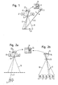
- CMOS type shown that has a radiation-sensitive image recording surface 15 comprises divided into a plurality of detection elements or pixels.
- a basically any design can be used as the imaging optics optical imaging device can be provided which e.g. a lens or includes a lens system.
- a radiation source 11 is provided, the wavelength of which is fundamentally is as long as the emitted radiation 17 by means of the sensor 23 is detectable.
- the radiation source 11 emitted radiation 17 is at a reflection surface 31, which is in a is the monitoring area 19 visible to the camera, reflected in such a way that it strikes the image recording surface 15 of the sensor 23, however, only one in the exemplary embodiment shown is comparative small portion 13 of the image recording surface 15 acted upon is illuminated.
- the position of the partial area 13 on the image recording surface 15 is of the relative arrangement of the radiation source 11 and the Image recording area 15 dependent. As shown by the double arrow 1 in FIG. 1 indicated, the radiation source 11 can be pivoted relative to the sensor 23 be, whereby the position of the partial surface 13 on the image recording surface 15 can be changed.
- the above-mentioned surveillance area 19 of the camera system can with the entire field of view that can be evaluated by means of the sensor 13 the camera collapse, but alternatively only one Show part of the view area.
- An evaluation device 25 of the invention which is only indicated in FIG. 3 Camera system is able to shift this Trigger area 13 on the image recording surface 15 based on a corresponding Detect change in the output signal of the sensor 23 and then initiate an image acquisition.
- the radiation source 11 and the Camera arranged in a common housing 35, whereby results in a compact recording unit that can be handled as a whole.
- FIG. 2a and 2b schematically show possibilities for automatic Triggering, each of which works according to the light barrier principle becomes.
- the relative arrangement of radiation source 11 and Image recording surface 15 of the sensor 23 is selected such that an in the radiation path crossing the surveillance area 19 of the camera Object reaching the path of the radiation 17 from the radiation source 11 to the image recording surface 15 interrupts, namely such that the radiation 17 does not reflect onto the image recording surface 15 becomes.
- the change that occurs here from the trigger sub-area 13 signal originating on the image recording surface 15 consists of the absence of the signal as soon as the beam path through the object is interrupted.
- the evaluation device 25 (cf. FIG. 4) is of this type formed that this absence of the non-recording signal is detected and then the image acquisition is started.
- Fig. 4 shows the spatial separate arrangement of radiation source 11 and image recording surface 15 on opposite sides of the surveillance area 19 of the camera system.
- a single radiation source 11 is provided, which to change the position of the trigger portion 13 on the Image recording surface 15 of sensor 23 can be moved relative to sensor 23 is how it is indicated by the double arrows.
- FIG. 2b there are several radiation sources 11 integrated in a edition for the objects to be recorded.
- Dependent on of the desired course of the trigger radiation 17 in Monitoring area 19 of the camera can selectively one of the radiation sources 11 can be activated. Since the entire image recording area 15 of the Sensor 23 for the small trigger portion 13 is available none for such changes in the path of propagation of radiation 17 Readjustment of the camera system required.
- the optics 33 in the exemplary embodiment according to FIGS. 1 and 2a of FIG a lighting device 37, which e.g. in the form of a flash ring is provided, which is activated when the image acquisition is triggered is only in this way for illumination of the monitoring area 19 to worry if this is to record each Object 21 is required.
- the image recording surface 15 with which the actual image recordings of objects, used at the same time to to provide a trigger signal by evaluating a partial area 13 of the image recording surface 15 provided in the non-recording state Signal by means of an evaluation device 25 designed for this is constantly checked for changes. As soon as the given Change condition occurs, the image acquisition by means of of the evaluation device 25, whereupon either the entire Image recording surface 15 or a predetermined partial area for implementation the actual image acquisition is read out.
- the evaluation device 25 can also by evaluating the Trigger radiation source 11 applied to partial area 13 of the image recording surface 15 in the non-recording state, the degree of pollution in Determine the propagation path of the trigger radiation 17 in this way perform a functional check and when a predetermined one is reached Degree of pollution e.g. to provide a warning signal.
- the degree of pollution in Determine the propagation path of the trigger radiation 17 in this way perform a functional check and when a predetermined one is reached Degree of pollution e.g. to provide a warning signal.
Landscapes
- Engineering & Computer Science (AREA)
- Multimedia (AREA)
- Signal Processing (AREA)
- Physics & Mathematics (AREA)
- General Physics & Mathematics (AREA)
- Studio Devices (AREA)
- Length Measuring Devices By Optical Means (AREA)
- Transforming Light Signals Into Electric Signals (AREA)
Abstract
Description
- Fig. 1
- rein schematisch in einer Seitenansicht eine Ausführungsform eines erfindungsgemäßen Kamerasystems, bei dem nach dem Lichttasterprinzip gearbeitet wird,
- Fig. 2a und 2b
- Ansichten entsprechend Fig. 1 weiterer Ausführungsformen eines erfindungsgemäßen Kamerasystems, bei dem nach dem Lichtschrankenprinzip gearbeitet wird,
- Fig. 3
- schematisch eine perspektivische Ansicht eines nach dem Lichttasterprinzip arbeitenden Kamerasystems gemäß einer weiteren Ausführungsform der Erfindung, und
- Fig. 4
- schematisch eine perspektivische Ansicht eines nach dem Lichtschrankenprinzip arbeitenden Kamerasystems gemäß einer weiteren Ausführungsform der Erfindung.
- 11
- Strahlungsquelle
- 13
- Teilbereich
- 15
- Bildaufnahmefläche
- 17
- Strahlung
- 19
- Überwachungsbereich
- 21
- Objekt
- 23
- Sensor
- 25
- Auswerteeinrichtung
- 31
- Reflexionsfläche
- 33
- Optik
- 35
- Gehäuse
- 37
- Beleuchtungseinrichtung
Claims (19)
- Verfahren zum Auslösen einer Bildaufnahme mittels wenigstens eines Kamerasystems, bei demin einem Nichtaufnahmezustand mittels zumindest einer Strahlungsquelle (11) wenigstens ein Teilbereich (13) einer Bildaufnahmefläche (15) des Kamerasystems beaufschlagt wird,das hierbei von der Bildaufnahmefläche (15) abgeleitete Signal einer Auswerteeinrichtung (25) zugeführt und als ein Nichtaufnahmesignal gewertet wird, undbei einer Änderung des Nichtaufnahmesignals automatisch die Bildaufnahme ausgelöst wird.
- Verfahren nach Anspruch 1,
dadurch gekennzeichnet, dass der Ausbreitungsweg der Strahlung (17) von der Strahlungsquelle (11) zur Bildaufnahmefläche (15) durch einen im Sichtbereich des Kamerasystems liegenden Überwachungsbereich (19) hindurch verläuft. - Verfahren nach Anspruch 1 oder 2,
dadurch gekennzeichnet, dass eine Verschiebung des mit Strahlung (17) von der Strahlungsquelle (11) beaufschlagten Teilbereiches (13) auf der Bildaufnahmefläche ( 15) als eine die Bildaufnahme auslösende Änderung gewertet wird. - Verfahren nach einem der vorhergehenden Ansprüche,
dadurch gekennzeichnet, dass das Beaufschlagen des Teilbereiches (13) der Bildaufnahmefläche (15) nach dem Lichttasterprinzip derart erfolgt, dass der Ausbreitungsweg der Strahlung (17) von der Strahlungsquelle (11) zur Bildaufnahmefläche (15) durch in einen Überwachungsbereich (19) des Kamerasystems gelangende Objekte (21) verändert wird. - Verfahren nach einem der vorhergehenden Ansprüche,
dadurch gekennzeichnet, dass das Ausbleiben der auf dem Teilbereich (13) der Bildaufnahmefläche (15) auftreffenden Strahlung (17) als eine die Bildaufnahme auslösende Änderung gewertet wird. - Verfahren nach einem der vorhergehenden Ansprüche,
dadurch gekennzeichnet, dass das Beaufschlagen des Teilbereiches (13) der Bildaufnahmefläche (15) nach dem Lichtschrankenprinzip derart erfolgt, dass der Ausbreitungsweg der Strahlung (17) von der Strahlungsquelle (11) zur Bildaufnahmefläche (15) durch in einen Überwachungsbereich (19) des Kamerasystems gelangende Objekte (21) unterbrochen wird. - Verfahren nach einem der vorhergehenden Ansprüche,
dadurch gekennzeichnet, dass der mittels der Strahlungsquelle (11) zu beaufschlagende Teilbereich (13) der Bildaufnahmefläche (15) vorgegeben wird und im Nichtaufnahmezustand ausschließlich dieser Teilbereich (13) ausgewertet wird. - Verfahren nach einem der vorhergehenden Ansprüche,
dadurch gekennzeichnet, dass der Ausbreitungsweg der Strahlung (17) von der Strahlungsquelle (11) zur Bildaufnahmefläche (15) einstellbar ist, insbesondere durch Bewegen der Strahlungsquelle (11) relativ zur Bildaufnahmefläche (15). - Verfahren nach einem der vorhergehenden Ansprüche,
dadurch gekennzeichnet, dass als Strahlungsquelle (11) zumindest ein Teil einer vorhandenen, zum Ausleuchten eines Überwachungsbereichs des Kamerasystems vorgesehenen Beleuchtungseinrichtung verwendet wird. - Verfahren nach einem der vorhergehenden Ansprüche,
dadurch gekennzeichnet, dass das Auslösen der Bildaufnahme das Aktivieren einer Beleuchtungseinrichtung (37) umfasst. - Verfahren nach einem der vorhergehenden Ansprüche,
dadurch gekennzeichnet, dass das durch Beaufschlagen des Teilbereiches (13) der Bildaufnahmefläche (15) erhaltene Signal zur Funktionsüberprüfung, insbesondere zur Bestimmung des Verschmutzungsgrades, verwendet wird, wobei vorzugsweise hierzu die Intensität der den Teilbereich (13) beaufschlagenden Strahlung überwacht wird. - Verfahren nach einem der vorhergehenden Ansprüche,
dadurch gekennzeichnet, dass ein Kamerasystem nach einem der nachstehenden Ansprüche verwendet wird. - Kamerasystem mit wenigstens einer Bildaufnahmefläche (15), einer Auswerteeinrichtung (25) zum Auslesen der Bildaufnahmefläche (15) und zumindest einer Strahlungsquelle (11), mittels welcher in einem Nichtaufnahmezustand wenigstens ein Teilbereich (13) der Bildaufnahmefläche (15) beaufschlagbar ist, wobei die Auswerteeinrichtung (25) derart ausgebildet ist, dass das von dem beaufschlagten Teilbereich (13) der Bildaufnahmefläche (15) stammende Signal als ein Nichtaufnahmesignal gewertet, eine Änderung des Nichtaufnahmesignals erkannt und bei einer Änderung des Nichtaufnahmesignals automatisch ein Auslösesignal zum Auslösen einer Bildaufnahme erzeugt wird.
- Kamerasystem nach Anspruch 13,
dadurch gekennzeichnet, dass die Bildaufnahmefläche (15) von einem ortsauflösenden Sensor (23) gebildet ist, insbesondere von einem Sensor vom CMOS-, CCDoder CID-Typ. - Kamerasystem nach Anspruch 13 oder 14,
dadurch gekennzeichnet, dass die Strahlungsquelle (11) relativ zur Bildaufnahmefläche (15) bewegbar ist. - Kamerasystem nach einem der Ansprüche 13 bis 15,
dadurch gekennzeichnet, dass die Strahlungsquelle (11) von der Bildaufnahmefläche (15) räumlich getrennt angeordnet ist. - Kamerasystem nach einem der Ansprüche 13 bis 15,
dadurch gekennzeichnet, dass die Bildaufnahmefläche (15) und die Strahlungsquelle (11) in eine gemeinsame Baueinheit integriert sind. - Kamerasystem nach einem der Ansprüche 13 bis 17,
dadurch gekennzeichnet, dass eine Anzeigeeinrichtung zum unterscheidbaren Anzeigen des Nichtaufnahmezustandes und des Aufnahmezustandes vorgesehen ist. - Kamerasystem nach einem der Ansprüche 13 bis 18,
dadurch gekennzeichnet, dass das Auslösen der Bildaufnahme gemäß einem Verfahren nach einem der Ansprüche 1 bis 12 erfolgt.
Applications Claiming Priority (2)
| Application Number | Priority Date | Filing Date | Title |
|---|---|---|---|
| DE10244162A DE10244162A1 (de) | 2002-09-23 | 2002-09-23 | Auslösen von Bildaufnahmen |
| DE10244162 | 2002-09-23 |
Publications (2)
| Publication Number | Publication Date |
|---|---|
| EP1401193A2 true EP1401193A2 (de) | 2004-03-24 |
| EP1401193A3 EP1401193A3 (de) | 2004-05-26 |
Family
ID=31896300
Family Applications (1)
| Application Number | Title | Priority Date | Filing Date |
|---|---|---|---|
| EP03020951A Ceased EP1401193A3 (de) | 2002-09-23 | 2003-09-16 | Auslösen von Bildaufnahmen |
Country Status (4)
| Country | Link |
|---|---|
| US (1) | US20040130627A1 (de) |
| EP (1) | EP1401193A3 (de) |
| JP (1) | JP2004274708A (de) |
| DE (1) | DE10244162A1 (de) |
Cited By (2)
| Publication number | Priority date | Publication date | Assignee | Title |
|---|---|---|---|---|
| WO2013007695A1 (fr) * | 2011-07-13 | 2013-01-17 | Trixell | Procédé de commande d'un détecteur photosensible par détection automatique d'un rayonnement incident |
| CN115508301A (zh) * | 2021-06-07 | 2022-12-23 | 迈恩德电子有限公司 | 检测装置和方法 |
Families Citing this family (2)
| Publication number | Priority date | Publication date | Assignee | Title |
|---|---|---|---|---|
| DE102006042908B4 (de) * | 2006-04-07 | 2009-11-12 | Eads Deutschland Gmbh | Verfahren zur Überwachung von Öffnungen an der Außenhaut von Luftfahrzeugen gegen unbefugtes Eindringen von Personen oder Sachen |
| FR2940000A1 (fr) * | 2008-12-17 | 2010-06-18 | Bernard Taillade | Systeme de securite perimetrique par l'analyse active de l'image d'une camera video |
Family Cites Families (12)
| Publication number | Priority date | Publication date | Assignee | Title |
|---|---|---|---|---|
| JPS57211044A (en) * | 1981-06-19 | 1982-12-24 | Hajime Sangyo Kk | Inspecting device |
| FR2645310B1 (fr) * | 1989-03-31 | 1991-06-21 | Elsydel | Procede d'identification d'objets en mouvement, notamment de vehicules, et systemes pour sa mise en oeuvre |
| DE4321261A1 (de) * | 1992-06-29 | 1994-02-24 | Strebel Engineering Kleindoett | Vorrichtung zum Prüfen von Formteilen |
| US5581297A (en) * | 1992-07-24 | 1996-12-03 | Intelligent Instruments Corporation | Low power video security monitoring system |
| KR960028217A (ko) * | 1994-12-22 | 1996-07-22 | 엘리 웨이스 | 움직임 검출 카메라 시스템 및 방법 |
| JPH09245269A (ja) * | 1996-03-06 | 1997-09-19 | Atsumi Electron Corp Ltd | 物体検知システム |
| US7196720B2 (en) * | 1998-03-06 | 2007-03-27 | Intel Corporation | Method and apparatus for powering on an electronic device with a video camera that detects motion |
| DE29911390U1 (de) * | 1999-06-30 | 1999-08-12 | Sick AG, 79183 Waldkirch | Optoelektronisches Überwachungssystem |
| TW473645B (en) * | 2000-11-22 | 2002-01-21 | Elecvision Inc | Method of displacement detection for digital camera |
| JP4167401B2 (ja) * | 2001-01-12 | 2008-10-15 | 富士フイルム株式会社 | ディジタル・カメラおよびその動作制御方法 |
| DE10119498C1 (de) * | 2001-04-20 | 2002-01-24 | Mikrotron Gmbh | Bildaufnahme-Auslöseeinrichtung, sowie Verfahren zum Auslösen einer Bildaufnahme |
| US20020163577A1 (en) * | 2001-05-07 | 2002-11-07 | Comtrak Technologies, Inc. | Event detection in a video recording system |
-
2002
- 2002-09-23 DE DE10244162A patent/DE10244162A1/de not_active Withdrawn
-
2003
- 2003-09-16 EP EP03020951A patent/EP1401193A3/de not_active Ceased
- 2003-09-22 US US10/668,112 patent/US20040130627A1/en not_active Abandoned
- 2003-09-22 JP JP2003330168A patent/JP2004274708A/ja active Pending
Cited By (7)
| Publication number | Priority date | Publication date | Assignee | Title |
|---|---|---|---|---|
| WO2013007695A1 (fr) * | 2011-07-13 | 2013-01-17 | Trixell | Procédé de commande d'un détecteur photosensible par détection automatique d'un rayonnement incident |
| FR2977977A1 (fr) * | 2011-07-13 | 2013-01-18 | Trixell | Procede de commande d'un detecteur photosensible par detection automatique d'un rayonnement incident |
| CN103931171A (zh) * | 2011-07-13 | 2014-07-16 | 曲克赛尔股份有限公司 | 用于通过自动检测入射辐射而控制光电探测器的方法 |
| US9069087B2 (en) | 2011-07-13 | 2015-06-30 | Trixell | Method for controlling a photodetector by automatically detecting incident radiation |
| CN103931171B (zh) * | 2011-07-13 | 2017-05-03 | 曲克赛尔股份有限公司 | 用于通过自动检测入射辐射而控制光电探测器的方法 |
| CN115508301A (zh) * | 2021-06-07 | 2022-12-23 | 迈恩德电子有限公司 | 检测装置和方法 |
| US12546728B2 (en) | 2021-06-07 | 2026-02-10 | Md Elektronik Gmbh | Device and method for optically capturing an object |
Also Published As
| Publication number | Publication date |
|---|---|
| US20040130627A1 (en) | 2004-07-08 |
| EP1401193A3 (de) | 2004-05-26 |
| DE10244162A1 (de) | 2004-04-01 |
| JP2004274708A (ja) | 2004-09-30 |
Similar Documents
| Publication | Publication Date | Title |
|---|---|---|
| DE602004009793T2 (de) | Verfahren und vorrichtung zur detektion von objekten durch die verwendung eines strukturierten beleuchtungsmusters | |
| DE102007008806C5 (de) | Optoelektronische Überwachung mit Test durch Dynamisierung | |
| EP2384295B2 (de) | Kameraanordnung und verfahren zur erfassung einer fahrzeugumgebung | |
| EP1991450B1 (de) | Kameraanordnung für ein kraftfahrzeug | |
| DE3926349C2 (de) | ||
| EP2118555B1 (de) | Sicherheitseinrichtung für eine maschine | |
| EP2338062B1 (de) | Verfahren und system zur ermittlung einer fahrzeuggeschwindigkeit | |
| EP2646802A1 (de) | Detektion von regentropfen auf einer scheibe mittels einer kamera und beleuchtung | |
| DE19628049C2 (de) | Vorrichtung zur Erfassung der Position eines menschlichen Körpers unter Verwendung eines Infrarotstrahlsensors | |
| DE102020112430B4 (de) | Kamera und Verfahren zur Erfassung von Objekten | |
| DE112014007223T5 (de) | Abstandssensor, Abstandserfassungsvorrichtung und Abstandserfassungsverfahren | |
| EP1988389B1 (de) | Überwachung eines Raumbereichs mit Bestimmung des Verschmutzungsgrads einer transparenter Grenzfläche anhand des Bildkontrasts | |
| WO2017041915A1 (de) | Sensorsystem einer sensoreinrichtung eines kraftfahrzeugs | |
| EP3910547B1 (de) | Erfassung von bewegten objekten | |
| DE29911390U1 (de) | Optoelektronisches Überwachungssystem | |
| EP1813961B1 (de) | Vorrichtung zur optoelektronischen Überwachung von Objekten | |
| EP1738580B1 (de) | Vorrichtung zum überwachen eines raumbereichs, insbesondere zum absichern eines gefahrenbereichs einer automatisiert arbeitenden anlage | |
| EP3139309A1 (de) | Sensoranordnung zur erfassung von probenkörpern | |
| DE10222685C1 (de) | Einrichtung und Verfahren zum Abtasten einer Vorlage | |
| WO2002028110A1 (de) | Verfahren zum überprüfen der funktionstüchtigkeit einer optischen detektionsvorrichtung sowie optische detektionsvorrichtung | |
| DE102006041307A1 (de) | Opto-elektronische Sensoranordnung | |
| DE10244162A1 (de) | Auslösen von Bildaufnahmen | |
| DE10017333A1 (de) | Schutzvorrichtung zum Absichern eines Gefahrenbereichs sowie Verfahren zum Überprüfen der Funktionssicherheit einer solchen | |
| EP1065522B1 (de) | Optoelektronisches Überwachungssystem | |
| EP3588130B1 (de) | Optischer sensor |
Legal Events
| Date | Code | Title | Description |
|---|---|---|---|
| PUAI | Public reference made under article 153(3) epc to a published international application that has entered the european phase |
Free format text: ORIGINAL CODE: 0009012 |
|
| AK | Designated contracting states |
Kind code of ref document: A2 Designated state(s): AT BE BG CH CY CZ DE DK EE ES FI FR GB GR HU IE IT LI LU MC NL PT RO SE SI SK TR |
|
| AX | Request for extension of the european patent |
Extension state: AL LT LV MK |
|
| PUAL | Search report despatched |
Free format text: ORIGINAL CODE: 0009013 |
|
| AK | Designated contracting states |
Kind code of ref document: A3 Designated state(s): AT BE BG CH CY CZ DE DK EE ES FI FR GB GR HU IE IT LI LU MC NL PT RO SE SI SK TR |
|
| AX | Request for extension of the european patent |
Extension state: AL LT LV MK |
|
| RIC1 | Information provided on ipc code assigned before grant |
Ipc: 7H 04N 3/15 A |
|
| 17P | Request for examination filed |
Effective date: 20040712 |
|
| AKX | Designation fees paid |
Designated state(s): AT BE BG CH CY CZ DE DK EE ES FI FR GB GR HU IE IT LI LU MC NL PT RO SE SI SK TR |
|
| 17Q | First examination report despatched |
Effective date: 20050408 |
|
| RAP1 | Party data changed (applicant data changed or rights of an application transferred) |
Owner name: SICK AG |
|
| 17Q | First examination report despatched |
Effective date: 20050408 |
|
| APBK | Appeal reference recorded |
Free format text: ORIGINAL CODE: EPIDOSNREFNE |
|
| APBN | Date of receipt of notice of appeal recorded |
Free format text: ORIGINAL CODE: EPIDOSNNOA2E |
|
| APBR | Date of receipt of statement of grounds of appeal recorded |
Free format text: ORIGINAL CODE: EPIDOSNNOA3E |
|
| APAF | Appeal reference modified |
Free format text: ORIGINAL CODE: EPIDOSCREFNE |
|
| APBT | Appeal procedure closed |
Free format text: ORIGINAL CODE: EPIDOSNNOA9E |
|
| STAA | Information on the status of an ep patent application or granted ep patent |
Free format text: STATUS: THE APPLICATION HAS BEEN REFUSED |
|
| 18R | Application refused |
Effective date: 20170407 |