EP1400983B1 - Kollimatorvorrichtung zum Einsatz in einem Zweischicht ElektronenstrahlScanner - Google Patents
Kollimatorvorrichtung zum Einsatz in einem Zweischicht ElektronenstrahlScanner Download PDFInfo
- Publication number
- EP1400983B1 EP1400983B1 EP03253606.2A EP03253606A EP1400983B1 EP 1400983 B1 EP1400983 B1 EP 1400983B1 EP 03253606 A EP03253606 A EP 03253606A EP 1400983 B1 EP1400983 B1 EP 1400983B1
- Authority
- EP
- European Patent Office
- Prior art keywords
- ray
- collimator
- patient
- fan beam
- detector
- Prior art date
- Legal status (The legal status is an assumption and is not a legal conclusion. Google has not performed a legal analysis and makes no representation as to the accuracy of the status listed.)
- Expired - Fee Related
Links
Images


Classifications
-
- A—HUMAN NECESSITIES
- A61—MEDICAL OR VETERINARY SCIENCE; HYGIENE
- A61B—DIAGNOSIS; SURGERY; IDENTIFICATION
- A61B6/00—Apparatus for radiation diagnosis, e.g. combined with radiation therapy equipment
- A61B6/40—Apparatus for radiation diagnosis, e.g. combined with radiation therapy equipment with arrangements for generating radiation specially adapted for radiation diagnosis
- A61B6/4021—Apparatus for radiation diagnosis, e.g. combined with radiation therapy equipment with arrangements for generating radiation specially adapted for radiation diagnosis involving movement of the focal spot
- A61B6/4028—Apparatus for radiation diagnosis, e.g. combined with radiation therapy equipment with arrangements for generating radiation specially adapted for radiation diagnosis involving movement of the focal spot resulting in acquisition of views from substantially different positions, e.g. EBCT
-
- A—HUMAN NECESSITIES
- A61—MEDICAL OR VETERINARY SCIENCE; HYGIENE
- A61B—DIAGNOSIS; SURGERY; IDENTIFICATION
- A61B6/00—Apparatus for radiation diagnosis, e.g. combined with radiation therapy equipment
- A61B6/02—Devices for diagnosis sequentially in different planes; Stereoscopic radiation diagnosis
- A61B6/03—Computerised tomographs
- A61B6/032—Transmission computed tomography [CT]
-
- G—PHYSICS
- G21—NUCLEAR PHYSICS; NUCLEAR ENGINEERING
- G21K—TECHNIQUES FOR HANDLING PARTICLES OR IONISING RADIATION NOT OTHERWISE PROVIDED FOR; IRRADIATION DEVICES; GAMMA RAY OR X-RAY MICROSCOPES
- G21K1/00—Arrangements for handling particles or ionising radiation, e.g. focusing or moderating
- G21K1/02—Arrangements for handling particles or ionising radiation, e.g. focusing or moderating using diaphragms, collimators
- G21K1/025—Arrangements for handling particles or ionising radiation, e.g. focusing or moderating using diaphragms, collimators using multiple collimators, e.g. Bucky screens; other devices for eliminating undesired or dispersed radiation
-
- A—HUMAN NECESSITIES
- A61—MEDICAL OR VETERINARY SCIENCE; HYGIENE
- A61B—DIAGNOSIS; SURGERY; IDENTIFICATION
- A61B6/00—Apparatus for radiation diagnosis, e.g. combined with radiation therapy equipment
- A61B6/06—Diaphragms
-
- A—HUMAN NECESSITIES
- A61—MEDICAL OR VETERINARY SCIENCE; HYGIENE
- A61B—DIAGNOSIS; SURGERY; IDENTIFICATION
- A61B6/00—Apparatus for radiation diagnosis, e.g. combined with radiation therapy equipment
- A61B6/40—Apparatus for radiation diagnosis, e.g. combined with radiation therapy equipment with arrangements for generating radiation specially adapted for radiation diagnosis
- A61B6/4064—Apparatus for radiation diagnosis, e.g. combined with radiation therapy equipment with arrangements for generating radiation specially adapted for radiation diagnosis specially adapted for producing a particular type of beam
- A61B6/4085—Cone-beams
Definitions
- Certain embodiments of the present invention generally relate to an electron beam tomography system, and more particularly to a collimator for a dual-slice electron beam tomography system.
- CT systems produce planar images along imaginary cuts, or slices, through a patient.
- CT systems typically include an x-ray source, which revolves about an imaginary axis through a subject. After passing through the subject, the x-rays impinge on an opposing array of detectors.
- Typical CT patient scans are executed in either an axial mode or in a helical mode.
- axial mode the table that supports the patient stops, the scan is executed, and then the table moves to a new location.
- helical mode the patient table continuously moves throughout the course of the scan.
- Single slice scanners scanners having one detector array
- dual slice CT systems systems having two detector arrays
- Some CT scanners include a scanning electron beam x-ray source, such that an electron beam is magnetically deflected so as to rotate in a generally arcuate path, and in doing so, impinges upon an arc-shaped target. As the electron beam impinges on the target, a source of x-rays is generated. As the electron beam moves, so does the source of x-rays. The x-rays encounter a collimator which passes a portion and blocks a portion of the x-rays. The x-rays are shaped into a fan beam by the collimator and then intercepted by a ring-shaped detector array on an opposite side of the patient.
- United States Patent No. 5,442,673, issued August 15, 1995 discloses an x-ray collimator for use within an electron beam computed tomography (EBT) scanner, in which a rotating electron beam is directed to impinge upon a ring shaped target.
- the '673 patent discloses variable tomographic slice width for a single slice EBT system. Single slice EBT systems, however, take longer to scan a given number of slices than corresponding dual slice systems.
- US 4,610,021 discloses a variable width fan beam of radiation in a high speed X-ray transmission system by a plurality of ring collimators with the ring collimators being mounted whereby spacing between ring collimators can be varied.
- an arcuate array of radiation detectors are mounted in an annular housing which functions as one of the ring collimators.
- Figures 6A to 6D illustrate the positions of collimator rings and detector ring in obtaining a two slice mode, a single slice mode, a thin slice mode, and a dual slice mode of operation
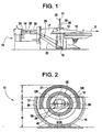
- FIG. 1 is a transverse cross-sectional view of an electron beam tomography (“EBT") system 10, formed in accordance with an embodiment of the present invention.
- the EBT system 10 includes an electron beam scan tube 12 having a cylindrical portion 14 and a semi-circular conical portion 17; and x-ray detector arrays 20 and 21.
- the scan tube 12 develops and projects an electron beam 26 towards a semi-circular ring-shaped target ("target ring") 16.
- the target ring 16 generates x-rays at portions thereof where the electron beam 26 impinges.
- the x-rays after being collimated and subsequently passed through the patient 18 lying along a patient axis denoted by line X, are intercepted and detected by at least one of the detector arrays 20 and/or 21.
- a data output of the detector array 20 and/or 21 is processed by a computer system (not shown) to form diagnostic images and other information of interest to a physician and the patient.
- Scan tube 12 includes a vacuum envelope 22, which houses an electron gun 24 in the cylindrical portion 14.
- the electron gun 24 projects the axial electron beam 26 through the semi-circular conical portion 17.
- Focus coils 28 magnetically focus the electron beam 26 to a spot, which impinges on the target ring 16.
- Bending coils 30 provide a magnetic field to bend the electron beam 26 so that it is directed through the semi-circular conical portion 17 toward the target ring 16.
- the bending coils 30 not only deflect the electron beam 26, but also rapidly and repeatedly sweep the electron beam 26 arcuately along the target ring 16 so as to create a source of x-rays that rotates substantially within a single plane.
- a collimator assembly 36 (shown in Figures 3-7 ) is disposed in the beam path between the target ring 16 and the detector arrays 20 and 21 so as to block the unwanted x-rays emitted by the target ring 16 and to define an x-ray beam projected as a one to ten millimeter thick planar fan beam.
- a sector of the x-ray fan beam is detected by a portion of the x-ray detector array 20 and/or 21, which provide measured values to the computer in response thereto.
- FIG. 2 is an axial cross-sectional view of an electron beam tomography (“EBT") system 10, formed in accordance with an embodiment of the present invention.
- the collimator assembly 36 may be donut or circular shaped to surround the scan field 39.
- the collimator assembly 36 collimates x-rays projecting from the target ring 16 and projecting onto the detector arrays 20 and 21.
- Only detector array 21 is visible, as detector array 20 is positioned behind and adjacent to detector array 21.
- the x-ray fan beam 38 is shown emanating from beam spot 40. That is, the electron beam 26 impinges on the target ring 16 at the beam spot 40, which in turn generates the x-ray fan beam 38.
- the target ring 16 and the detector arrays 20 and 21 overlap at an overlap region A.
- the source-only region of the EBT system 10 is denoted by the source-only region B; while the detector-only region is denoted by the detector-only region C.
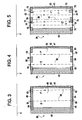
- Figure 3 is a cross-sectional view in a plane that contains axis line X of the collimator assembly 36 in the source-only region B, formed in accordance with an embodiment of the present invention.
- Figure 4 is a cross-sectional view in a plane that contains axis line X of the collimator assembly 36 in the detector-only region C, formed in accordance with an embodiment of the present invention.
- Figure 5 is a cross-sectional view in a plane that contains axis line X of the collimator assembly 36 in the overlap region A, formed in accordance with an embodiment of the present invention.
- the portion of the collimator assembly 36 in the source-only region B includes first and second rings 41 and 43, a cover 42 over the first ring 41, a first pre-patient x-ray surface 44, a second pre-patient x-ray surface 46 and an inner cavity 48 therebetween.
- the first pre-patient x-ray surface 44 includes a first x-ray inlet aperture 50 and a second x-ray inlet aperture 52.
- the second pre-patient x-ray surface 46 includes a first x-ray outlet aperture 51 and a second x-ray outlet aperture 53.
- the first and second pre-patient x-ray surfaces 44 and 46 may be covered by Lexan®, or any other material that allows x-rays to pass through, while at the same time, maintaining the structural integrity of the collimator assembly 36.
- the x-ray fan beam 38 is generated from the target ring (not shown in Figure 3 ) toward the patient axis X, as shown by the arrows of beams E and F.
- the x-ray fan beam is collimated through the apertures formed between the blocking portions 54.
- the blocking portions 54 may be formed of steel, lead, brass, or other materials that impede the progress of x-rays.
- the x-ray fan beam 38 may pass through the apertures 50-53, but is blocked by the blocking portions 54.
- the x-ray fan beam 38 is collimated through the source-only region B before the x-ray fan beam 38 passes through the patient. That is, as discussed below, the x-ray fan beam 38 passes through the collimator assembly 36 in the source-only region B before the x-ray fan beam 38 encounters the patient along the axis denoted by line X and the portion of the collimator assembly 36 in the detector-only region C.
- the collimator assembly 36 may be positioned such that the following tomographic slices ("slices") may be used to image a patient: (1.) one intermediate slice on one detector array 21 ("one intermediate slice”); (2.) one thin slice on detector array 20 and one thin slice on detector array 21 ("two thin slices”); (3.) one thick slice on both detector arrays 20 and 21 ("one thick slice”); or (4.) one intermediate slice on detector array 20 and one intermediate slice on detector array 21 ("two intermediate slices”).
- the "one thick slice” is obtained by using the same collimator position as the "two intermediate slices,” but the outputs of the two detectors 20 and 21 are added either electrically or digitally.
- the thick, intermediate and thin slices may range in width from 10 mm to 1 mm.
- the slice widths depend on the widths of the apertures 51 and 53.
- the apertures 50-53 may be sized differently to accommodate different sized slices.
- the x-ray fan beam (the center of which is represented by reference line E) may pass through the first x-ray inlet aperture 50, through the inner cavity 48, and then through the first x-ray outlet aperture 51. Then, the x-ray fan beam 38 passes through the patient 18 lying along the axis denoted by line X, then through the collimator assembly 36 at the detector-only region A, until it impinges on one or both of the detector arrays 20 or 21. Because Figure 3 only shows the collimator assembly 36 in the source only region B, the x-ray fan beam 38 that passes through the collimator assembly 36 in the source-only region B has yet to pass through the patient 18.
- the collimator assembly 36 is positioned to obtain one intermediate slice the collimated x-ray fan beam 38 impinges on detector array 21 when the cone angle of the x-ray fan is minimized. If, however, the collimator assembly 36 is positioned to obtain two equal width slices, such as two thin slices, one half of the collimated x-ray fan beam 38 impinges on the first detector array 20, while the second half of the collimated x-ray fan beam 38 impinges on the second detector array 21.
- the collimator assembly 36 may also be mechanically shifted, either through an actuator, an operator, or the like, to a second position such that the x-ray fan beam 38 may pass through the second x-ray inlet aperture 52 to the second x-ray oulet aperture 53 (with the center of the x-ray fan beam 38 being denoted by reference line F).
- the second x-ray inlet aperture 52 may be a different size than the first x-ray inlet aperture 50 and the second x-ray outlet aperture 53 may be a different size than the first x-ray outlet aperture 51.
- different size slices may be obtained depending upon whether the first or second x-ray inlet and outlet apertures 50 and 51 or 52 and 53 are used, which is determined by the position of the collimator assembly 36.
- the collimator assembly 36 may be in a first position to obtain a first single slice (such as the single intermediate slice if the x-ray fan beam 38 passes through the first x-ray inlet aperture 50 and first x-ray outlet aperture 51), a second position to obtain a first double slice (such as two thin slices if the x-ray fan beam 38 passes through the first x-ray inlet and outlet apertures 50 and 51, respectively); a third position to obtain a second single slice (such as the single thick slice if the x-ray fan beam 38 passes through the second x-ray inlet aperture 52 and the second x-ray outlet aperture 53); and the third position to obtain a second double slice (such as two intermediate slices if the x-ray fan beam 38 passes through the second x-ray inlet and outlet apertures 52 and 53, respectively).
- the collimator assembly 36 may be moved, actuated, or otherwise shifted through multiple positions to obtain different slice thicknesses and combinations.
- the detector assembly (including detector arrays 20 and 21) is also
- the collimator assembly 36 may be shifted through three different positions, while the detector arrays 20 and 21 are shifted through two different positions to provide four different slice configurations. That is, the collimator assembly 36 may be in a first position, while the detector arrays are in a first position to provide a first slice configuration. The collimator assembly 36 may be in a second position, while the detector arrays 20 and 21 are in a second position to provide a second slice configuration. Further, the collimator assembly 36 may be in a third position, while the detector arrays 20 and 21 are in the second position to provide a third and fourth slice configurations.
- the portion of the collimator assembly 36 in the detector-only region C includes the first ring 41, the cover 42 and second ring 43. Additionally, the collimator assembly 36 in the detector-only region C includes a first post-patient x-ray surface 58, a second post-patient x-ray surface 60 and an inner cavity 62.
- the first post-patient x-ray surface 58 includes a first x-ray inlet aperture 64 and a second x-ray inlet aperture 66.
- the second post-patient x-ray surface 60 includes a first x-ray outlet aperture 65 and a second x-ray outlet aperture 67.
- the first and second post-patient x-ray surfaces 58 and 60 may be covered with Lean®, or any other material that allows x-rays to pass through, while at the same time, maintaining the structural integrity of the collimator assembly 36.
- the x-ray fan beam 38 passes through the collimator assembly 36 in the detector-only region C after the x-ray fan beam 38 passes through the source-only region B and the patient lying along the axis X. It is noted that E' and F' represent that the x-ray fan beam 38 has passed through the patient lying along the axis X; whereas E and F, as shown in Figure 3 , represent that the x-ray fan beam 38 has not yet passed through the patient.
- the x-ray fan beam 38 is a collimated beam. That is, the collimator assembly 36 collimates the x-ray fan beam 38 into a collimated beam.
- the x-ray fan beam 38 passes through the patient lying along the axis X. After passing through the patient, the x-ray fan beam 38 passes through the first post-patient x-ray surface 58, through the inner cavity 62, and then through the second post-patient x-ray surface 60.
- the blocking portions 54 may be formed of steel, lead, brass, or other materials that impede the progress of x-rays.
- the collimated x-ray fan beam 38 may pass through the apertures 64-67. The blocking portions 54 prevent scattered x-rays from reaching the detector arrays 20 and 21.
- the collimator assembly 36 may be positioned such that the following tomographic slices may be used to image a patient: (1.) one intermediate slice; (2.) two thin slices; (3.) one thick slice; or (4.) two intermediate slices.
- the slice thickness depends on the width of the apertures 51 and 53.
- the apertures 64-67 may be sized differently to accommodate different size slices. For example, if the collimator is set in a first position, the x-ray fan beam (the center of which is represented by reference line E') may pass through the first x-ray inlet aperture 64, then through the inner cavity 62, and through the x-ray outlet aperture 65. Then, the x-ray fan beam 38 impinges on one or both of the detector arrays 20 or 21.
- the collimator assembly 36 may also be shifted to a second position such that the x-ray fan beam 38 may pass from the second x-ray inlet aperture 66 to the second x-ray outlet aperture 67 (with the center of the x-ray fan beam 38 being denoted by reference line F').
- the second x-ray inlet aperture 66 may be a different size than the first x-ray inlet aperture 64; while the second x-ray outlet aperture 67 may be a different size than the first x-ray outlet aperture 65.
- different sized slices may be accommodated depending on the position of the collimator assembly 36.
- the collimator assembly 36 may be in a first position to obtain one intermediate slice (when the x-ray fan beam 38 passes through the first x-ray inlet aperture 64 and the first x-ray outlet aperture 65), a second position to obtain two thin slices (when the x-ray fan beam 38 passes through the first x-ray inlet and outlet apertures 64 and 65, respectively); a third position to obtain one thick slice (when the x-ray fan beam 38 passes through the second x-ray inlet aperture 66 and second x-ray outlet aperture 67); and the same third position to obtain two intermediate slices (when the x-ray fan beam 38 passes through the second x-ray inlet and outlet apertures 66 and 67, respectively).
- the apertures 64-67 are wider than the apertures 50-53 to accommodate the width of the x-ray fan beam 38. That is, the collimated x-ray fan beam 38 is wider near the detector arrays 20 and 21 than by the target ring 16, which is the x-ray source.
- the portion of the collimator assembly 36 in the overlap region A includes the first ring 41, the second ring 43, and the cover 42 over the first ring 41. Additionally, the collimator assembly 36 in the overlap region A includes a first x-ray surface 70, a second x-ray surface 72 and an inner cavity 73.
- the x-ray surface 44, 60 and 70 are physically the same cylindrical surface; and x-ray surface 46, 58 and 72 are physically a second cylindrical surface.
- Cavities 48, 62 and 73 are the same donut shaped cavity.
- Each aperture pair 50, 74; 51, 75; 52, 76; 53, 77; 64, 78; 65, 79; 66, 80 and 67, 81 is physically a single continuous aperture.
- the first x-ray surface 70 includes a first pre-patient x-ray inlet aperture 74, a second pre-patient x-ray inlet aperture 76, a first post-patient x-ray outlet aperture 79, and a second post-patient x-ray outlet aperture 81.
- the second x-ray surface 72 includes a first pre-patient x-ray outlet aperture 75, second pre-patient x-ray outlet aperture 77, a first post-patient x-ray inlet aperture 78 and a second post-patient x-ray inlet aperture 80.
- the portion of the collimator within the overlap region A includes x-ray inlet and outlet apertures on both x-ray surfaces 70 and 72 to accommodate the sweeping of the x-ray fan beam 38. That is, at a first radial angle, the x-ray fan beam 38 passes through the collimator assembly 36 in the overlap region A before it passes through the patient 18 lying along the axis X. However, when the x-ray fan beam 38 is radially rotated toward the other side of the collimator assembly 36, the same portion of the collimator assembly 36 in the overlap region receives the x-ray fan beam 38 after the x-ray fan beam 38 passes through the patient 18 lying along the axis X.
- the beam spot (i.e., the point from which the x-ray fan beam 38 emanates) may be at the position marked by reference numeral 84.
- the beam spot may then be swept to a position denoted by reference numeral 86.
- the collimator assembly 36 includes corresponding apertures to accommodate both pre and post patient x-ray fan beams.
- the first and second x-ray surfaces 70 and 72 may be covered with Lexan®, or any other material that allows x-rays to pass through, while at the same time, maintaining the structural integrity of the collimator assembly 36.
- the x-ray fan beam 38 passes between the apertures as described above with respect to Figure 3 and 4 .
- the x-ray fan beam 38 (the center of which is denoted by line E, for a pre-patient x-ray fan beam 38) passes from the first pre-patient x-ray inlet aperture 74 to the first pre-patient x-ray outlet aperture 75.
- the x-ray fan beam 38 then passes through the patient and encounters the other side of the collimator assembly 36 in the overlap region, such that the x-ray fan beam passes between an analogous first post-patient x-ray inlet aperture 78' to an analogous first post-patient x-ray outlet aperture 79' (the center of the post-patient beam is denoted by reference line E').
- the collimator assembly 36 is shifted such that the x-ray fan beam 38 passes from the second pre-patient x-ray inlet aperture 76 to the second pre-patient x-ray outlet aperture 77.
- the x-ray fan beam 38 then passes through the patient lying along the axis X. After passing through the patient, the x-ray fan beam 38 encounters the corresponding other side of the collimator assembly 36 in the overlap region A such that the post patient x-ray fan beam 38 passes from an analogous second post-patient x-ray inlet aperture 80' to an analogous second post-patient x-ray outlet aperture 81'.
- Figure 6 is a cross-sectional view in a plane that contains axis line X of Figure 1 of both sides of the collimator assembly 36 in the overlap region A, formed in accordance with an embodiment of the present invention.
- the horizontal scale is approximately 4:1, while the vertical scale is approximately 1:10.
- Figure 6 represents the one intermediate slice and two thin slice portion of the EBT system 10. The narrower the slice width, the better the axial resolution (narrower slice widths also result in reduced dosage to the patient).
- Figure 6 illustrates the EBT system 10 on the left side of reference line G, shown in Figure 5 .
- the patient 18 lies along the axis X.
- the x-ray fan beam 38 emanates from the beam spot 40.
- the x-ray fan beam 38 has sides 138 and 238.
- the x-ray fan beam 38 passes from the first pre-patient x-ray inlet aperture 74 through the first pre-patient x-ray outlet aperture 75.
- the x-ray fan beam 38 then passes through the patient lying along the axis X.
- the x-ray fan beam 38 then passes through the first post-patient x-ray inlet aperture 78' on through the first post-patient x-ray outlet aperture 79'.
- the apertures 74, 75, 78, 79 are formed such that the x-ray fan beam 38 impinges on the detector array(s) at a first intermediate width.
- the collimator assembly 36 When the collimator assembly 36 is in a first position, as shown in Figure 6 , one half of the x-ray fan beam 38 impinges on the first detector 20, while the other half of the x-ray fan beam 38 impinges on the second detector 21 (thus, two thin slices are detected). However, the collimator assembly 36 and detector arrays 20 and 21 may be shifted to a second position such that x-ray fan beam 38 impinges only on the second detector 21 (resulting in one intermediate slice).
- reference slot 222 shows where the first pre-patient x-ray outlet 75 shifts (thus, the other apertures would also shift), for the x-ray fan beam defined by sides 338 and 438 to impinge solely on the second detector 21.
- the x-ray fan beam 38 may be swept through a 180 degree radial arc such that the x-ray fan beam 38' emanates from beam spot 40'.
- the electron fan beam 38' is defined by sides 138' and 238'.
- Figure 7 is a cross-sectional view of both sides of the collimator assembly 36 in the overlap region A, formed in accordance with an embodiment of the present invention.
- the horizontal scale is approximately 4:1, while the vertical scale is approximately 1:10.
- Figure 7 represents the one thick slice and two intermediate slice portions of the EBT system 10. That is, Figure 7 illustrates the EBT system 10 on the right side of reference line G, shown in Figure 5 .
- the patient 18 lies along the axis X.
- the x-ray fan beam 38 emanates from the beam spot 40.
- the x-ray fan beam 38 has sides 138 and 238.
- the x-ray fan beam 38 passes from the second pre-patient x-ray inlet aperture 76 through the first pre-patient x-ray outlet aperture 77.
- the x-ray fan beam 38 then passes through the patient lying along the axis X.
- the x-ray fan beam 38 then passes through the second post-patient x-ray inlet aperture 80' on through the second post-patient x-ray outlet aperture 81'.
- the apertures 76, 77, 80 and 81; (and 76', 77', 80' and 81') are formed such that the x-ray fan beam 38 impinges on the detector array(s) at a thick width.
- the collimator assembly 36 When the collimator assembly 36 is in the position, as shown in Figure 7 , one half of the x-ray fan beam 38 impinges on the first detector 20, while the other half of the x-ray fan beam 38 impinges on the second detector 21 (resulting in two intermediate slices). However, data from the two detector arrays 20 and 21 may be added resulting in one thick slice. Additionally, the x-ray fan beam 38 may be swept through a 180 degree arc such that the x-ray fan beam 38' emanates from beam spot 40'. In this case, the electron fan beam 38' is defined by sides 138' and 238'.
- the collimator assembly 36 of the EBT system 10 is not limited to the slice configurations described above.
- a wide variety of slice configurations, in addition to the one thick, two intermediate, one intermediate, and two thin slice configurations, may be implemented within the system.
- the collimator may include more apertures that may allow for an increased number of slice configurations.
- the collimator may include more than two sets of x-ray inlet and outlet apertures. That is, the collimator may include a set of apertures for one thick/ two intermediate slices, another set of apertures for one intermediate/ two thin slices, another set of apertures for one thin slice/two very thin slices, etc.
- more than two detector arrays may be used. For example, instead of having two detector arrays aligned with, and adjacent one another, three or more detector arrays may be utilized. Also, multiple target rings may be used within the EBT system.
- embodiments of the present invention provide a more efficient (and less expensive) dual-slice EBT scanner, because a single collimator may be used to collimate an x-ray fan beam at a plurality of slice widths.
Claims (3)
- Elektronenstrahl-(26)-Tomographie-(EBT)-Scansystem (10), aufweisend:eine Elektronenquelle (24) zum Erzeugen eines Elektronenstrahlbündels (26);einen Anodenring (16), der das Elektronenstrahlbündel (26) aus der Elektronenquelle (24) aufnimmt, wobei der Anodenring (16) ein Röntgen-Fächerstrahlbündel (38) nach dem Auftreffen des Elektronenstrahlbündels (26) auf den Anodenring (16) emittiert;ein dem Anodenring (16) gegenüberliegend angeordnetes Paar von Detektorarrays (20, 21), die das Röntgen-Fächerstrahlbündel (38) detektieren; undeinen konzentrisch zwischen dem Anodenring (16) und dem Paar der Detektorarrays (20, 21) angeordneten Kollimator (36), wobei der Kollimator (36) konzentrisch zueinander angeordnete und einen Patientenuntersuchungsbereich (39) umgebende Innen- und Außenwände besitzt, wobei die Innen- und Außenwände erste Gruppen von Öffnungen darin haben, wobei die erste Gruppe von Öffnungen zum Kollimieren des Röntgen-Fächerstrahlbündels (38) in ein erstes kollimiertes Strahlbündel mit einer ersten Breite ausgerichtet ist, wobei das erste kollimierte Strahlbündel durch das erste und zweite Detektorarray detektiert werden kann, wenn sich der Kollimator (36) in einer ersten Position befindet, während sich gleichzeitig die Detektorarrays in einer ersten Position befinden; wobei das erste kollimierte Strahlbündel ferner durch eines von dem ersten und dem zweiten Detektorarray (20, 21) detektiert werden kann, wenn der Kollimator (36) in eine zweite Kollimatorposition bewegt wird und die Detektorarrays (20, 21) in eine zweite Position bewegt werden; wobei die zweite Gruppe von Öffnungen zum Kollimieren des Röntgen-Fächerstrahlbündels (38) in ein zweites kollimiertes Strahlbündel mit einer zweiten Breite ausgerichtet ist, wobei das zweite kollimierte Strahlbündel durch das erste und zweite Detektorarray (20, 21) detektiert werden kann, wenn der Kollimator (36) in eine dritte Kollimatorposition bewegt wird, wobei der Kollimator (36) zwischen der ersten, zweiten und dritten Kollimatorposition in Bezug auf den Anodenring (16) bewegt werden kann, um das erste und zweite kollimierte Strahlbündel mit der ersten bzw. zweiten Breite zu definieren.
- EBT-Scansystem (10) nach Anspruch 1, wobei der Kollimator (36) zwischen der ersten und zweiten Kollimatorposition in Bezug auf den Anodenring (16) bewegt werden kann, um das erste kollimierte Strahlbündel ausschließlich auf nur einen Detektor (20) und (21) von dem Paar der Detektoren (20) und (21) zu lenken, wenn er sich in der ersten Kollimatorposition befindet, und auf beide Detektoren (20) und (21) von dem Paar der Detektoren (20) und (21), wenn er sich in der zweiten Kollimatorposition befindet.
- EBT-Scansystem (10) nach einem der vorstehenden Ansprüche, wobei der Kollimator (36) einen Nur-Detektorbereich (10) mit einer ersten Gruppe von hinter dem Patienten befindlichen Röntgenstrahlöffnungen aufweist, um das Paar der Detektorarrays (20, 21) gegenüber gestreuten Röntgenstrahlen abzuschirmen; und einen zweiten Satz von hinter dem Patienten befindlichen Röntgenstrahlöffnungen, um das Paar der Detektorarrays (20, 21) gegenüber gestreuten Röntgenstrahlen abzuschirmen.
Applications Claiming Priority (2)
| Application Number | Priority Date | Filing Date | Title |
|---|---|---|---|
| US10/064,182 US6792077B2 (en) | 2002-06-19 | 2002-06-19 | Collimation system for dual slice EBT scanner |
| US64182 | 2008-02-21 |
Publications (3)
| Publication Number | Publication Date |
|---|---|
| EP1400983A2 EP1400983A2 (de) | 2004-03-24 |
| EP1400983A3 EP1400983A3 (de) | 2009-06-24 |
| EP1400983B1 true EP1400983B1 (de) | 2013-08-14 |
Family
ID=29731589
Family Applications (1)
| Application Number | Title | Priority Date | Filing Date |
|---|---|---|---|
| EP03253606.2A Expired - Fee Related EP1400983B1 (de) | 2002-06-19 | 2003-06-06 | Kollimatorvorrichtung zum Einsatz in einem Zweischicht ElektronenstrahlScanner |
Country Status (4)
| Country | Link |
|---|---|
| US (1) | US6792077B2 (de) |
| EP (1) | EP1400983B1 (de) |
| JP (1) | JP4361759B2 (de) |
| IL (1) | IL156350A (de) |
Families Citing this family (20)
| Publication number | Priority date | Publication date | Assignee | Title |
|---|---|---|---|---|
| DE102004061347B3 (de) * | 2004-12-20 | 2006-09-28 | Siemens Ag | Röntgen-Computertomograph für schnelle Bildaufzeichung |
| EP1677254A1 (de) | 2004-12-30 | 2006-07-05 | GSF-Forschungszentrum für Umwelt und Gesundheit GmbH | Verfahren und Vorrichtung zur Kollimierung eines Beaufschlagungsstrahles |
| EP1727092A1 (de) | 2005-05-23 | 2006-11-29 | GSF-Forschungszentrum für Umwelt und Gesundheit GmbH | Verfahren und Vorrichtung zur Computertomographie |
| US20080302950A1 (en) * | 2005-08-11 | 2008-12-11 | The Brigham And Women's Hospital, Inc. | System and Method for Performing Single Photon Emission Computed Tomography (Spect) with a Focal-Length Cone-Beam Collimation |
| US7187750B1 (en) * | 2005-09-20 | 2007-03-06 | General Electric Company | Method and apparatus for compensating non-uniform detector collimator plates |
| US7281850B2 (en) * | 2005-10-03 | 2007-10-16 | General Electric Company | Method and apparatus for aligning a fourth generation computed tomography system |
| US7496181B2 (en) * | 2005-11-28 | 2009-02-24 | The Board Of Trustees Of The Leland Stanford Junior University | X-ray collimator for imaging with multiple sources and detectors |
| CN2899841Y (zh) * | 2006-04-13 | 2007-05-16 | 邱炎雄 | 一种医用放射治疗射源装置结构 |
| EP2010058B1 (de) | 2006-04-14 | 2017-05-17 | William Beaumont Hospital | Computertomographiesystem und -methode |
| US8983024B2 (en) | 2006-04-14 | 2015-03-17 | William Beaumont Hospital | Tetrahedron beam computed tomography with multiple detectors and/or source arrays |
| US9339243B2 (en) | 2006-04-14 | 2016-05-17 | William Beaumont Hospital | Image guided radiotherapy with dual source and dual detector arrays tetrahedron beam computed tomography |
| CA2905989C (en) | 2006-05-25 | 2017-01-24 | Di Yan | Real-time, on-line and offline treatment dose tracking and feedback process for volumetric image guided adaptive radiotherapy |
| WO2011084878A1 (en) | 2010-01-05 | 2011-07-14 | William Beaumont Hospital | Intensity modulated arc therapy with continuous couch rotation/shift and simultaneous cone beam imaging |
| DE102012005767A1 (de) * | 2012-03-25 | 2013-09-26 | DüRR DENTAL AG | Phasenkontrast-Röntgen-Tomographiegerät |
| CN103356216B (zh) * | 2012-03-31 | 2015-08-05 | 上海西门子医疗器械有限公司 | Ct机的扫描成像方法、扫描成像系统及ct机 |
| KR102065158B1 (ko) * | 2012-07-05 | 2020-01-10 | 아메리칸 사이언스 앤 엔지니어링, 인크. | 가변 각도 시준기 |
| DE102013206252A1 (de) * | 2013-04-09 | 2014-10-09 | Helmholtz-Zentrum Dresden - Rossendorf E.V. | Anordnung zur schnellen Elektronenstrahl-Röntgencomputertomographie |
| MX364612B (es) | 2014-06-27 | 2019-05-02 | Anvil Int Llc | Abrazadera ajustable y cubo para soporte de manguera flexible. |
| CN108450030B (zh) | 2015-09-10 | 2021-02-26 | 美国科学及工程股份有限公司 | 使用行间自适应电磁x射线扫描的反向散射表征 |
| US11193898B1 (en) | 2020-06-01 | 2021-12-07 | American Science And Engineering, Inc. | Systems and methods for controlling image contrast in an X-ray system |
Citations (2)
| Publication number | Priority date | Publication date | Assignee | Title |
|---|---|---|---|---|
| US5222114A (en) * | 1990-05-30 | 1993-06-22 | Hitachi, Ltd. | X-ray analysis apparatus, especially computer tomography apparatus and x-ray target and collimator therefor |
| US6094469A (en) * | 1998-10-21 | 2000-07-25 | Analogic Corporation | Computed tomography system with stable beam position |
Family Cites Families (7)
| Publication number | Priority date | Publication date | Assignee | Title |
|---|---|---|---|---|
| US4352021A (en) | 1980-01-07 | 1982-09-28 | The Regents Of The University Of California | X-Ray transmission scanning system and method and electron beam X-ray scan tube for use therewith |
| US4531226A (en) * | 1983-03-17 | 1985-07-23 | Imatron Associates | Multiple electron beam target for use in X-ray scanner |
| US4610021A (en) * | 1984-06-13 | 1986-09-02 | Imatron, Inc. | X-ray transmission scanning system having variable fan beam geometry |
| IL98945A0 (en) | 1991-07-24 | 1992-07-15 | Elscint Ltd | Multiple slice ct scanner |
| US5442673A (en) * | 1994-03-30 | 1995-08-15 | Siemens Aktiengesellschaft | Fixed septum collimator for electron beam tomography |
| US6275562B1 (en) | 1998-04-28 | 2001-08-14 | General Electric Company | Apparatus and methods for performing scalable multislice computed tomography scan |
| RU2164081C2 (ru) * | 1999-04-27 | 2001-03-20 | Кванта Вижн, Инк. | Устройство для малоугловой рентгеновской томографии |
-
2002
- 2002-06-19 US US10/064,182 patent/US6792077B2/en not_active Expired - Lifetime
-
2003
- 2003-05-30 JP JP2003153795A patent/JP4361759B2/ja not_active Expired - Fee Related
- 2003-06-06 EP EP03253606.2A patent/EP1400983B1/de not_active Expired - Fee Related
- 2003-06-09 IL IL156350A patent/IL156350A/en active IP Right Grant
Patent Citations (2)
| Publication number | Priority date | Publication date | Assignee | Title |
|---|---|---|---|---|
| US5222114A (en) * | 1990-05-30 | 1993-06-22 | Hitachi, Ltd. | X-ray analysis apparatus, especially computer tomography apparatus and x-ray target and collimator therefor |
| US6094469A (en) * | 1998-10-21 | 2000-07-25 | Analogic Corporation | Computed tomography system with stable beam position |
Also Published As
| Publication number | Publication date |
|---|---|
| IL156350A (en) | 2007-10-31 |
| EP1400983A2 (de) | 2004-03-24 |
| EP1400983A3 (de) | 2009-06-24 |
| JP2004033757A (ja) | 2004-02-05 |
| US20030235271A1 (en) | 2003-12-25 |
| JP4361759B2 (ja) | 2009-11-11 |
| IL156350A0 (en) | 2004-01-04 |
| US6792077B2 (en) | 2004-09-14 |
Similar Documents
| Publication | Publication Date | Title |
|---|---|---|
| EP1400983B1 (de) | Kollimatorvorrichtung zum Einsatz in einem Zweischicht ElektronenstrahlScanner | |
| US6434219B1 (en) | Chopper wheel with two axes of rotation | |
| US6735271B1 (en) | Electron beam computed tomographic scanner system with helical or tilted target, collimator, and detector components to eliminate cone beam error and to scan continuously moving objects | |
| US7187756B2 (en) | X-ray CT apparatus and X-ray tube | |
| US4573179A (en) | Scanned projection radiography using high speed computed tomographic scanning system | |
| JP2005537846A (ja) | Ctスキャナ用の散乱防止x線遮蔽 | |
| JPS63501735A (ja) | 改良されたx線減衰方法および装置 | |
| JP2004033757A5 (de) | ||
| US4610021A (en) | X-ray transmission scanning system having variable fan beam geometry | |
| JP2004077486A (ja) | 多重焦点x線検査システム | |
| JP6649410B2 (ja) | X線ビームを生成し、かつ、コリメートするためのシステム | |
| JPH05256950A (ja) | X線コンピュータトモグラフィ装置用固体検出器 | |
| US6687332B2 (en) | Method and apparatus for patient-in-place measurement and real-time control of beam-spot position and shape in a scanning electron beam computed tomographic system | |
| US4126786A (en) | Radiography | |
| EP2067389A2 (de) | Kompakte e-strahlen-quelle zur erzeugung von röntgenstrahlen | |
| US9808209B2 (en) | Collimator for use in a CT system | |
| JP3730319B2 (ja) | X線コンピュータ断層撮影装置 | |
| US5442673A (en) | Fixed septum collimator for electron beam tomography | |
| US4172978A (en) | Radiography | |
| JP5458305B2 (ja) | X線コンピュータ断層撮影装置 | |
| GB2137453A (en) | Improvements in high energy computed tomography | |
| EP3322341B1 (de) | Bildgebung mit modulierter röntgenstrahlung | |
| JPS631698B2 (de) | ||
| JP5616436B2 (ja) | トモグラフィ装置及びトモグラフィ方法 | |
| EP0973048B1 (de) | Verfahren und Vorrichtung zur Verringerung von spektralen Artefakten im Computer-Tomographiesystem |
Legal Events
| Date | Code | Title | Description |
|---|---|---|---|
| PUAI | Public reference made under article 153(3) epc to a published international application that has entered the european phase |
Free format text: ORIGINAL CODE: 0009012 |
|
| AK | Designated contracting states |
Kind code of ref document: A2 Designated state(s): AT BE BG CH CY CZ DE DK EE ES FI FR GB GR HU IE IT LI LU MC NL PT RO SE SI SK TR |
|
| AX | Request for extension of the european patent |
Extension state: AL LT LV MK |
|
| PUAL | Search report despatched |
Free format text: ORIGINAL CODE: 0009013 |
|
| AK | Designated contracting states |
Kind code of ref document: A3 Designated state(s): AT BE BG CH CY CZ DE DK EE ES FI FR GB GR HU IE IT LI LU MC NL PT RO SE SI SK TR |
|
| AX | Request for extension of the european patent |
Extension state: AL LT LV MK |
|
| 17P | Request for examination filed |
Effective date: 20091228 |
|
| 17Q | First examination report despatched |
Effective date: 20100127 |
|
| AKX | Designation fees paid |
Designated state(s): DE NL |
|
| RIC1 | Information provided on ipc code assigned before grant |
Ipc: G21K 1/02 20060101AFI20120904BHEP Ipc: A61B 6/03 20060101ALI20120904BHEP |
|
| GRAP | Despatch of communication of intention to grant a patent |
Free format text: ORIGINAL CODE: EPIDOSNIGR1 |
|
| GRAS | Grant fee paid |
Free format text: ORIGINAL CODE: EPIDOSNIGR3 |
|
| GRAA | (expected) grant |
Free format text: ORIGINAL CODE: 0009210 |
|
| AK | Designated contracting states |
Kind code of ref document: B1 Designated state(s): DE NL |
|
| REG | Reference to a national code |
Ref country code: DE Ref legal event code: R096 Ref document number: 60344709 Country of ref document: DE Effective date: 20131010 |
|
| REG | Reference to a national code |
Ref country code: NL Ref legal event code: T3 |
|
| PLBE | No opposition filed within time limit |
Free format text: ORIGINAL CODE: 0009261 |
|
| STAA | Information on the status of an ep patent application or granted ep patent |
Free format text: STATUS: NO OPPOSITION FILED WITHIN TIME LIMIT |
|
| 26N | No opposition filed |
Effective date: 20140515 |
|
| REG | Reference to a national code |
Ref country code: DE Ref legal event code: R097 Ref document number: 60344709 Country of ref document: DE Effective date: 20140515 |
|
| PGFP | Annual fee paid to national office [announced via postgrant information from national office to epo] |
Ref country code: NL Payment date: 20170626 Year of fee payment: 15 |
|
| PGFP | Annual fee paid to national office [announced via postgrant information from national office to epo] |
Ref country code: DE Payment date: 20170628 Year of fee payment: 15 |
|
| REG | Reference to a national code |
Ref country code: DE Ref legal event code: R119 Ref document number: 60344709 Country of ref document: DE |
|
| REG | Reference to a national code |
Ref country code: NL Ref legal event code: MM Effective date: 20180701 |
|
| PG25 | Lapsed in a contracting state [announced via postgrant information from national office to epo] |
Ref country code: NL Free format text: LAPSE BECAUSE OF NON-PAYMENT OF DUE FEES Effective date: 20180701 |
|
| PG25 | Lapsed in a contracting state [announced via postgrant information from national office to epo] |
Ref country code: DE Free format text: LAPSE BECAUSE OF NON-PAYMENT OF DUE FEES Effective date: 20190101 |