EP1400716A1 - Kupplungssystem und Halteanordnung zum Halten wenigstens einer Kupplungsanordnung des Kupplungssystems in einem momentanen oder vorgegebenen Einrückzustand - Google Patents
Kupplungssystem und Halteanordnung zum Halten wenigstens einer Kupplungsanordnung des Kupplungssystems in einem momentanen oder vorgegebenen Einrückzustand Download PDFInfo
- Publication number
- EP1400716A1 EP1400716A1 EP03021283A EP03021283A EP1400716A1 EP 1400716 A1 EP1400716 A1 EP 1400716A1 EP 03021283 A EP03021283 A EP 03021283A EP 03021283 A EP03021283 A EP 03021283A EP 1400716 A1 EP1400716 A1 EP 1400716A1
- Authority
- EP
- European Patent Office
- Prior art keywords
- arrangement
- actuator
- clutch
- holding
- coupling
- Prior art date
- Legal status (The legal status is an assumption and is not a legal conclusion. Google has not performed a legal analysis and makes no representation as to the accuracy of the status listed.)
- Granted
Links
Images


Classifications
-
- F—MECHANICAL ENGINEERING; LIGHTING; HEATING; WEAPONS; BLASTING
- F16—ENGINEERING ELEMENTS AND UNITS; GENERAL MEASURES FOR PRODUCING AND MAINTAINING EFFECTIVE FUNCTIONING OF MACHINES OR INSTALLATIONS; THERMAL INSULATION IN GENERAL
- F16D—COUPLINGS FOR TRANSMITTING ROTATION; CLUTCHES; BRAKES
- F16D28/00—Electrically-actuated clutches
-
- F—MECHANICAL ENGINEERING; LIGHTING; HEATING; WEAPONS; BLASTING
- F16—ENGINEERING ELEMENTS AND UNITS; GENERAL MEASURES FOR PRODUCING AND MAINTAINING EFFECTIVE FUNCTIONING OF MACHINES OR INSTALLATIONS; THERMAL INSULATION IN GENERAL
- F16D—COUPLINGS FOR TRANSMITTING ROTATION; CLUTCHES; BRAKES
- F16D21/00—Systems comprising a plurality of actuated clutches
- F16D21/02—Systems comprising a plurality of actuated clutches for interconnecting three or more shafts or other transmission members in different ways
- F16D21/06—Systems comprising a plurality of actuated clutches for interconnecting three or more shafts or other transmission members in different ways at least two driving shafts or two driven shafts being concentric
-
- F—MECHANICAL ENGINEERING; LIGHTING; HEATING; WEAPONS; BLASTING
- F16—ENGINEERING ELEMENTS AND UNITS; GENERAL MEASURES FOR PRODUCING AND MAINTAINING EFFECTIVE FUNCTIONING OF MACHINES OR INSTALLATIONS; THERMAL INSULATION IN GENERAL
- F16D—COUPLINGS FOR TRANSMITTING ROTATION; CLUTCHES; BRAKES
- F16D23/00—Details of mechanically-actuated clutches not specific for one distinct type
- F16D23/12—Mechanical clutch-actuating mechanisms arranged outside the clutch as such
- F16D23/14—Clutch-actuating sleeves or bearings; Actuating members directly connected to clutch-actuating sleeves or bearings
-
- F—MECHANICAL ENGINEERING; LIGHTING; HEATING; WEAPONS; BLASTING
- F16—ENGINEERING ELEMENTS AND UNITS; GENERAL MEASURES FOR PRODUCING AND MAINTAINING EFFECTIVE FUNCTIONING OF MACHINES OR INSTALLATIONS; THERMAL INSULATION IN GENERAL
- F16D—COUPLINGS FOR TRANSMITTING ROTATION; CLUTCHES; BRAKES
- F16D25/00—Fluid-actuated clutches
- F16D25/08—Fluid-actuated clutches with fluid-actuated member not rotating with a clutching member
- F16D25/082—Fluid-actuated clutches with fluid-actuated member not rotating with a clutching member the line of action of the fluid-actuated members co-inciding with the axis of rotation
- F16D25/087—Fluid-actuated clutches with fluid-actuated member not rotating with a clutching member the line of action of the fluid-actuated members co-inciding with the axis of rotation the clutch being actuated by the fluid-actuated member via a diaphragm spring or an equivalent array of levers
-
- F—MECHANICAL ENGINEERING; LIGHTING; HEATING; WEAPONS; BLASTING
- F16—ENGINEERING ELEMENTS AND UNITS; GENERAL MEASURES FOR PRODUCING AND MAINTAINING EFFECTIVE FUNCTIONING OF MACHINES OR INSTALLATIONS; THERMAL INSULATION IN GENERAL
- F16D—COUPLINGS FOR TRANSMITTING ROTATION; CLUTCHES; BRAKES
- F16D25/00—Fluid-actuated clutches
- F16D25/12—Details not specific to one of the before-mentioned types
-
- F—MECHANICAL ENGINEERING; LIGHTING; HEATING; WEAPONS; BLASTING
- F16—ENGINEERING ELEMENTS AND UNITS; GENERAL MEASURES FOR PRODUCING AND MAINTAINING EFFECTIVE FUNCTIONING OF MACHINES OR INSTALLATIONS; THERMAL INSULATION IN GENERAL
- F16D—COUPLINGS FOR TRANSMITTING ROTATION; CLUTCHES; BRAKES
- F16D21/00—Systems comprising a plurality of actuated clutches
- F16D21/02—Systems comprising a plurality of actuated clutches for interconnecting three or more shafts or other transmission members in different ways
- F16D21/06—Systems comprising a plurality of actuated clutches for interconnecting three or more shafts or other transmission members in different ways at least two driving shafts or two driven shafts being concentric
- F16D2021/0607—Double clutch with torque input plate in-between the two clutches, i.e. having a central input plate
-
- F—MECHANICAL ENGINEERING; LIGHTING; HEATING; WEAPONS; BLASTING
- F16—ENGINEERING ELEMENTS AND UNITS; GENERAL MEASURES FOR PRODUCING AND MAINTAINING EFFECTIVE FUNCTIONING OF MACHINES OR INSTALLATIONS; THERMAL INSULATION IN GENERAL
- F16D—COUPLINGS FOR TRANSMITTING ROTATION; CLUTCHES; BRAKES
- F16D21/00—Systems comprising a plurality of actuated clutches
- F16D21/02—Systems comprising a plurality of actuated clutches for interconnecting three or more shafts or other transmission members in different ways
- F16D21/06—Systems comprising a plurality of actuated clutches for interconnecting three or more shafts or other transmission members in different ways at least two driving shafts or two driven shafts being concentric
- F16D2021/0646—Electrically actuated clutch with two clutch plates
-
- F—MECHANICAL ENGINEERING; LIGHTING; HEATING; WEAPONS; BLASTING
- F16—ENGINEERING ELEMENTS AND UNITS; GENERAL MEASURES FOR PRODUCING AND MAINTAINING EFFECTIVE FUNCTIONING OF MACHINES OR INSTALLATIONS; THERMAL INSULATION IN GENERAL
- F16D—COUPLINGS FOR TRANSMITTING ROTATION; CLUTCHES; BRAKES
- F16D2300/00—Special features for couplings or clutches
- F16D2300/14—Clutches which are normally open, i.e. not engaged in released state
Definitions
- the invention relates to a clutch system comprising a Friction clutch device for arrangement in the drive train of a motor vehicle with at least one mechanical acting in the disengaging direction Restoring forces engaging clutch assembly and an actuator to initiate acting against the restoring forces in the sense of engagement Actuating forces of an actuator arrangement based indentation forces in the Friction clutch device to engage the clutch assembly actuate.
- Friction clutch device for arrangement in the drive train of a motor vehicle with at least one mechanical acting in the disengaging direction Restoring forces engaging clutch assembly and an actuator to initiate acting against the restoring forces in the sense of engagement Actuating forces of an actuator arrangement based indentation forces in the Friction clutch device to engage the clutch assembly actuate.
- Such coupling systems of the NORMALLY OPEN type (NORMALLY OPEN or NO type) are mainly used as wet-running clutches Slat type known, specifically also as so-called double and Multiple clutches for so-called powershift or double clutch transmissions, at which each of several clutch arrangements (in the case mentioned here known type
- Such double clutches have received more attention recently experience because they are based on a so-called "overlap circuit in Combined with an automatically shiftable transmission, a high level of driving comfort similar to a conventional automatic transmission with a torque converter promise, but have a higher efficiency.
- One of is the preferred design for such a wet-running double clutch known for example from DE 100 04 179 A1.
- Dry-running clutches of the friction disc type are conventional from NORMALLY CLOSED type (NORMALLY CLOSED or NC type), and are only activated during the switching process.
- the duty cycle of the actuator is typically between 1 to 5% of the clutch Operating time of the vehicle. It is for double or multiple clutch systems
- the coupling arrangements of respective coupling device are of the NORMALLY-OPEN type. hereby it is guaranteed that in the event of an error not both or several Coupling arrangements are closed or close at the same time and the This tensions the drive train or even serious damage in the Powertrain occur.
- the object of the invention is to at least partially solve the mentioned Problems to provide a solution.
- the inventors asked themselves whether as is the case with a coupling system of the type specified at the outset on the energy balance and / or the resilience of components could be possible, the coupling system or the at least one coupling arrangement of the same in to maintain an engagement state that is maintaining or at least approximately maintaining a current operating state or Driving state of the vehicle enables without the actuator arrangement actuating forces must be constantly generated.
- one of the friction clutch devices or / and the clutch arrangement or / and the actuating device or / and the Actuator arrangement associated holding arrangement is provided, by means of which the Coupling arrangement against the action of the restoring forces regardless of the Generation of actuation forces by the actuator arrangement in one current engagement state or one of the current engagement state associated hold engagement state is durable.
- the current engagement state or at least one of the current Assigned state of engagement assigned, for example, adjacent half-engagement state hold without the engaging clutch assembly Actuator arrangement must constantly generate actuation forces. So it can for example a current position of a pressure plate or a general one State of pressure of the friction surface arrangement by means of the holding arrangement maintained or instead of the current position or status maintain an associated hold position or hold state without an electric motor of the clutch actuator or the like has to be energized permanently.
- the holding arrangement is for the maintenance the position or the state or for holding the hold position or the hold state usually only need an auxiliary energy.
- the respective NORMALLY OPEN system behavior can be done easily mechanical energy storage can be achieved, such as in the case of Coupling arrangement on the friction surfaces and / or an associated Actuate in the disengaging direction or in the case of the holding arrangement Remove hold between components that are assigned to each other.
- Insist here basically various options, some of which are preferred below be addressed specifically.
- Suitable control devices for the actuation of the Coupling arrangement or a respective one of several coupling arrangements Friction clutch devices are for example from DE 37 06 849 A1 and DE 197 29 997 A1 known.
- advantageously usable actuator is on the German patent application filed on October 9, 2001 "Actuating device for a Friction clutch device, possibly double or multiple friction clutch device ", official file number 101 49 703.2 and / or submission has come or is coming, the priority of which is claimed subsequent registrations referenced.
- the actuating device can advantageously be at least one of the Coupling arrangement associated actuator include that relative to at least one axially substantially stationary support member for exerting the Engagement forces is axially adjustable and associated with one of the clutch arrangement Actuator belongs or through the intermediary of one of the clutch arrangement associated actuator is axially adjustable relative to the support member.
- One can be advantageous such engagement between the actuator and the support member is provided be the one given to the actuator through the intermediary of the actuator Rotational movement relative to the support member supported against rotation in a axial translational movement of the actuator relative to the axially supported Support member is implemented to operate the clutch assembly in the sense of engagement.
- the / an actuator of the Actuator with an output part of the preferably electromotive Actuator is motion-coupled or motion-coupled.
- the garnish part can be an output part that can be rotated or pivoted about an axis.
- the coupling mechanism can be at least one movable, in particular rotatably or pivotably arranged input part which with the Output part of the actuator is motion-coupled or can be motion-coupled, exhibit. Furthermore, the coupling mechanism can advantageously move at least one in particular rotatably or pivotably arranged output part, which with the Actuator has motion-coupled or motion-coupled. It should be noted that the input part and the output part are of a single Component can be formed or parts of an integral or one-piece design Component group or a one-piece component can be.
- a practical embodiment of the coupling system is characterized by this from that at least one pressure plate of the friction clutch device one / the coupling mechanism can be actuated by the actuator, the coupling mechanism a translatory or rotary actuating movement in an actuating movement of the Pressure plate.
- the actuator Tappet which can be actuated translationally directly or via at least one engagement lever the pressure plate act.
- one through the actuator at least rotationally operable eccentrics directly or via at least one Engaging lever acts on the pressure plate.
- the holding arrangement can on at least one of the parts mentioned above or limbs work. It is generally suggested the holding arrangement for this is formed, at least one link 'from one / the actuator to one friction surface arrangement which can be brought into engagement with one another in pairs by frictional engagement leading chain of operation in a current position or one of the to hold the current position assigned to this adjacent stop position.
- the actuation chain is the / an output part of the actuator and possibly at least one internal part that is motion-coupled to the output part, in particular transmission part or actuating part, include within the actuator can.
- the actuating chain can have at least one at least one friction surface the component of the clutch arrangement comprising the friction surface arrangement. With reference to the possibilities of training the Actuator is advised that the actuation chain that Actuator and possibly at least one coupling part, especially the input part or / and output part, which can include coupling mechanics.
- the link in question that is the link which by the holding arrangement in the current position or one of the current Position assigned to this adjacent stop position can be held can be brought into holding engagement with an associated holding member of the holding arrangement.
- the holding engagement can be a form-fitting engagement or a force-fitting for example, frictional engagement.
- a "stepless" Provide lockability or fixability of the link in question suggested that the limb in question has an associated one continuous range of motion in any current position the holding engagement with the holding member is durable. But for many purposes it will also suffice if the link in question is only in discrete steps or given (For example, geometrically predetermined) steps can be locked or fixed. For this purpose, it is proposed that the link in question has one of these assigned continuous range of motion only in a plurality of predetermined discrete holding positions by the holding engagement with the holding member is durable.
- At least one actuator is separate from the actuator be provided by means of which the link in question and the holding member to be assigned can be brought into holding engagement.
- at least one actuator can be provided by means of which the holding engagement between the relevant member and the associated holding member can be canceled.
- a plurality of predetermined discrete stop positions are used in this context suggested that based on one about the clutch assembly too transmitting torque and / or on the basis of a possibly occurring Slip speed of the clutch arrangement, the actuator can be controlled and / or Holding member is adjustable relative to the member in question, to one on the transmitting torque or / and a specification regarding the slip speed or adjust the slippage-free stop position, if necessary in Interacting with an adjustment of the relevant link by means of the actuator. So you will be using a lock that is in discrete steps or approximately Geometrically predetermined levels works, usually an acceptable adjustment can reach the respective load state of the clutch arrangement.
- clutch slip occurs (a relative speed) on.
- the clutch slip or the relative speed can be advantageous as Input signal for activating the actuator and / or the actuator are used to set the next locking level, if necessary engage.
- the transfer case can For example, have a wet-running multi-plate clutch, which for Torque transmission must be engaged by applying appropriate Operating forces. So it can be, for example, a clutch from Act "NORMALLY OPEN" type. It is for such an arrangement advantageous if the current clutch condition of the multi-plate clutch, in particular a more or less strongly engaged clutch state of the Multi-plate clutch, is held when the system is de-energized or de-energized. This can be achieved in a simple manner, for example, by the fact that Actuator an electric motor with built-in motor brake is used.
- the actuator at least one electric motor, at least one electrically excitable magnet, at least one bimetal element with an associated heating element arrangement, at least a piezo element arrangement or at least one based on a pressure fluid Has actuatable power cylinder arrangement for generating actuating forces.
- the actuator the link in question is.
- the holding arrangement can be in a / Actuator of the actuator arrangement can be integrated. It was especially the Possibility addressed that as an actuator an electric motor with a built-in Motor brake is used, the motor brake is designed to be de-energized State of the electric motor a momentary actuation state of the Electric motor, in particular a current rotational position of the / the output part of the electric motor.
- the or a Coupling part of the coupling mechanism in particular the input part and / or that Starting part of the coupling mechanism, the link in question.
- a particularly preferred embodiment of the actuating device is characterized in that the output part of the actuator and the / Input part of the coupling mechanism via a worm or gear drive are motion-linked or a motion coupling Form worm or gear drives. It is specifically suggested that the input part of the coupling mechanism designed as a gear or gear segment or a motion-coupled or motion-coupled Tappet element for direct or indirect coupling to the actuator relevant link is.
- the Coupling arrangement is primarily thought that this is a dry-running Coupling arrangement, and preferably a coupling arrangement of the Type of friction disc is.
- the coupling device can be a double or multiple coupling device can, with a first clutch arrangement assigned to a first gear train and a second clutch arrangement associated with a second gear train can be actuated independently of one another by means of a respective actuator.
- the each coupling arrangement can specifically be a respective one, an input for the be assigned to the respective gear train representing the transmission input shaft.
- the holding force that can be applied by the actuator alternately affects only one of the subsystems, which is based on a clever arrangement of the various components practically without further ado is feasible. For most requirements, it will be enough that just one of the subsystems, which is usually the one currently carrying the torque Subsystem, locked by means of the holding arrangement or in the engagement state or hold-engagement state can be held. From the use of only one actuator there are corresponding cost advantages.
- both subsystems can be locked or locked in simultaneously be held in a current engagement state or hold engagement state.
- the coupling arrangement is a wet clutch arrangement is preferably of the lamella type.
- a such coupling arrangement or a corresponding one Friction clutch device comes, for example, as or in connection with the above-mentioned transfer case in an all-wheel drive motor vehicle into consideration.
- Coupling device come between the drive unit and the transmission also wet-running clutch arrangements of the lamella type advantageous in Consideration.
- the invention also provides a holding arrangement for holding at least one Coupling arrangement of a coupling system according to the invention in one current engagement state or one of the current engagement state associated hold engagement condition regardless of the generation of Actuating forces by one engaging the clutch assembly Actuator arrangement ready.
- the invention also provides a motor vehicle powertrain that includes a Drive unit and a transmission and a friction clutch device for Has torque transmission between the drive unit and the transmission.
- the Motor vehicle drive train according to the invention is characterized by a coupling system according to the invention, which the Has friction clutch device.
- the invention further relates to a motor vehicle drive train, the one Has drive unit and a transmission, and a distribution friction clutch device having distributor arrangement for distributing a drive torque delivered by the transmission between driven or drivable front wheels of the motor vehicle, on the one hand, and driven or drivable rear wheels of the motor vehicle, on the other hand.
- the motor vehicle drive train is characterized by clutch system according to the invention, the friction clutch device as Distributing friction clutch device is used. It should be noted that not necessarily a friction clutch device between the drive unit and the Gear must be provided.
- the transmission as Automatic transmission with an upstream torque converter. is however, a friction clutch device for torque transmission between of the drive unit and the transmission, this can be used by the Friction clutch device of / a clutch system according to the invention be educated.
- Fig. 1 shows a double clutch 10 of the friction disc type, the first Clutch disc 12 of a first clutch assembly and a second Has clutch disc 14 of a second clutch arrangement.
- the first Clutch disc 12 is with a first designed as a hollow shaft Transmission input shaft. 16 and the second clutch disc 14 stands with one Coaxially extending through the first transmission input shaft 16 second Transmission input shaft 18 in a manner known per se in Torque transmission connection.
- the one with integrated torsional vibration dampers Clutch plates 202 and 204 have, for example, a Coupling hub 20 or 22 on the relevant transmission input shaft is pushed on and is coupled to it in a rotationally fixed manner via entrainment formations.
- the double clutch 10 has a housing arrangement 24, for example several housing parts connected to one another by bolts or the like includes.
- the housing arrangement 24 is on the output shaft via a flexible plate 80 84 of the drive unit, in particular an internal combustion engine, connected.
- An annular section of the first bearing friction linings on both sides Clutch disc 12 is axially between an abutment for the Clutch disc forming plate section 32 of the housing arrangement and a first pressure plate 34 held axially movable in the housing arrangement arranged.
- the second clutch disk 14 is with its friction linings on both sides bearing ring area axially between which an abutment for the clutch disc forming pressure plate section 32 and one in the housing arrangement axially movably held second pressure plate 36.
- the two pressure plates are each in a manner known per se by means of tangential springs (Tangential leaf springs) or the like held in the housing assembly 24 and spring-loaded in each case in the opening or disengaging direction.
- the first pressure plate 34 is a first plate or diaphragm spring 40 and second pressure plate 36 is assigned a second plate or diaphragm spring 60.
- first pressure plate 34 is a first plate or diaphragm spring 40
- second pressure plate 36 is assigned a second plate or diaphragm spring 60.
- the Diaphragm springs 40 and 60 primarily act as actuation levers for Engaging the respective pressure plate 34 or 36 against the respective, on the Abutment 32 axially supportable clutch disc with their actuating tongues or Actuating levers 50 and 70 in the direction of the clutch disks, that is to say in FIG. 1 to the left.
- the one arranged in the manner of a one-armed lever Membrane spring 40 acts directly or via an intermediate element on the in close Neighboring the pressure plate 34 arranged in the manner of a Two-arm lever arranged diaphragm spring 60, however, is below Mediation of a support ring 243 attacking its outer radius Power transmission member 66 and one by the housing arrangement and Pressure plate section 32 extending tie rod assembly 68 with the pressure plate 36 in connection.
- the Actuating module has a gear housing in particular against rotation secured central sleeve 220, which has an outer sleeve 222 and an inner sleeve 224 wearing.
- the outer sleeve 222 and the inner sleeve 224 are each over a External thread or internal thread engages with the central sleeve 220 such that a rotation of the outer sleeve and / or the inner sleeve relative to the central sleeve axial displacement of the relevant sleeve (outer sleeve or inner sleeve) induced.
- the outer sleeve 222 is provided with an engagement bearing 226, and the inner sleeve 224 is provided with an engagement bearing 228, via the mediation of the outer sleeve or inner sleeve axial forces on the diaphragm spring tongues of the diaphragm spring 40 or 60 can be exercised to the actuating tongues of the respective Deflect diaphragm spring towards the drive unit and thus the first or / and to actuate the second clutch arrangement in the direction of engagement.
- the Engagement bearings 226 and 228 can be configured with spring washers 324 and 326 to provide self-centering of the respective bearing.
- the sleeves can, for example, with radially protruding Lever arms or lever sections; to which an assigned one Actuator acts.
- a lever arm of the inner sleeve is 340 in Fig. 1 and a lever arm Outer sleeve is designated 342 in FIG. 1.
- 322 and 320 denote an am the intended force arm or lever section, for example in the manner of a spherical cap, to a substantially tangential to be able to exert directed actuating force on the respective sleeve.
- actuation module 200 comprising the unit Central sleeve 220 via a radial and axial bearing 230 with the housing arrangement of the Double clutch in support relationship.
- 232 denotes an intended one Ring section of a housing part of the housing arrangement.
- the radial and axial bearing 230 can by a locking ring, not shown, between the ring portion 232 and the central sleeve 220 may be axially fixed.
- FIG. 2 shows a double clutch 10, which is shown in somewhat more detail, with reference to FIG. 1 explained type together with an associated actuation module 200 and via the module actuator system 400 acting on the two clutch arrangements of the double clutch.
- the Actuator module 200 of the type shown in FIG. 1 or similar is one stationary support sleeve, for example central sleeve and rotatable relative to this and axially movable actuating sleeves, for example an inner sleeve or Outer sleeve, the actuating sleeves in a suitable manner, for example via a thread, are in engagement with the support sleeve in order to To convert rotary movement into an axial movement.
- the actuator system has two electromechanical ones Actuators 402 and 404 in particular based on electric motors, which have a Coupling mechanism 406 or 408 on a respectively assigned actuating sleeve of the Actuating module 200 and thus via the diaphragm spring 40 or 60 to each assigned of the two clutch arrangements act.
- the invention proposes, for example, as Locking mechanism or braking mechanism executed holding arrangement to provide a current engagement state or the current Indented state associated hold indented state of the respective Coupling assembly can hold without the electric motors Clutch actuator 400 must be energized permanently.
- preferred Variants of this holding arrangement only need for this holding an auxiliary energy.
- a lock or position fixation in the whole Actuating chain between the pressure plate of the respective coupling arrangement and the electromechanical actuating element, such as an electric motor, of the respective Actuator can be realized, in addition to a non-positive, for example frictional locking or position fixing also a positive Locking or position fixing can be provided and the locking or Position fixation can work continuously or in discrete steps.
- a stepless locking or position fixing is advantageous, so that a Coupling state can be kept, in that just from Torque output is transmitted so that an internal combustion engine Overpressure is not necessary.
- the time shares of the operation of the Internal combustion engines in the partial load range are usually very high, with the Partial load range required contact forces are comparatively low and accordingly, generally very short travel paths of the actuator suffice. Small travels with small force levels reduce that Actuation work and improve the energy balance. This advantage remains if with a stepless locking or position fix a momentary Coupling state of the respective coupling arrangement can be kept.
- a stepless locking of the actuator system 400 is in the embodiment of FIG. 2 realized.
- the actuator system which is connected to an output element 410 or 412 of the respective actuator 402 or 404 in the manner of a gear transmission or Worm gear engaged gear segment 414 or 416 and one preferably has pusher 417 or 418 held thereon in a pivotable manner its other end remote from the gear segment 414 or 416 to one each associated one of the actuating sleeves of the actuating module 200 acts with one optionally acting on one of the two gear segments 414 or 416 Holding arrangement 430 executed, the electromechanical actuator 432 and a by the actuator 432 axially adjustable plate-shaped holding member 434.
- a connecting rod between the actuator 432 and the holding element 434 extends along the common axis of rotation of the two gear segments 414 and 416.
- One of the gear segments 414 and 416 rotatable and the actuator 432 including the holding member 434 and the actuators 402 and 404 stationary holding support arrangement is not shown in the figures.
- the holding member 434 is in a central position or neutral position by a spring 436 spring biased between the two gear segments 414 and 416.
- the holding member 434 can optionally with the gear segment 414 or the gear segment 416 or one on the respective gear segment provided friction lining are brought into frictional holding engagement, so that a current rotational or swivel position of the respective gear segment 414 or 416 and thus a current coupling state of the assigned Coupling arrangement is held.
- the return spring 436 forcibly moves the holding member 434 into the Neutral position, so that the holding arrangement 430 has a NORMALLY OPEN system behavior and thus, if provided, for the entire chain of operations between the actuators 402, 404 and the clutch arrangements as a whole advantageous NORMALLY OPEN system behavior is realized.
- the holding arrangement 430 of FIGS. 2 and 3 can also suitably be used as a "brake” are referred to, instead of the term “locking” used above, the one may suggest positive intervention.
- locking is used more generally used and in particular also includes a frictional fixation.
- gear segment 414 is a separate one Holding arrangement 430a with the electromechanical actuator 432a and associated holding plate 434a and a return spring 436a assigned
- gear segment 416 is also a separate holding arrangement 430b with the electromechanical actuator 432b, the associated holding plate 434b and one Return spring 436b assigned.
- the friction lining is 440a and a friction lining arranged on the gear segment 416 is designated 440b.
- the electromechanical design of the actuator 432 or the Actuators 432a and 432b are only a practical example. It's coming too other operating principles for the provision of a corresponding actuator in Consider, for example, a piezo element arrangement or a holding element bimetal element arrangement. Another option is a pressure fluid operated Actuator.
- the holding arrangement on another element of the actuating chain for example on the output links 410 and 412 of the actuators 402 and 404, on the actuating plungers 417 and 418 or also directly on the actuators, possibly actuating sleeves, the Actuating module 200.
- An attack on the output member of the respective actuator or even a holding arrangement integrated in the actuator has the advantage that the Reduction of the relevant gear segment 414 or 416 also in relation to the holding forces applied by the holding arrangement is effective and in this respect lower Holding forces are sufficient.
- stepless locking or position fixation approximately according to the 1 to 4 comes in discrete steps or stages, if necessary, geometrically predetermined levels, working locking into consideration.
- levels and choice of the number of levels can easily an acceptable adaptation to the respective load condition of the concerned Coupling arrangement can be achieved.
- One can lock level Select the torque that is currently applied so that the Coupling arrangement can transmit the torque further.
- Fig. 5 shows an example of a gradual locking like a Snap-in protruding assembly 430c.
- an actuator for example actuator 402 acts on Gear segment, in the present case the gear segment 414.
- the gear segment is included a grid 450 executed with the one pivoted on a stationary support arranged pawl 452 can positively engage.
- the pawl 452 is by a return spring 454 in the direction of lifting from the grid 450 biased.
- the pawl 452 is designed as the arm of a two-armed lever, the other Arm 456 cooperates with an actuator 458, such that when the Actuator 458 the arm 456 pulled in the direction of arrow S and thus the Locking blade 452 against the restoring action of the spring 454 in engagement with the in Discrete steps performed screening 450 is pivoted.
- Fig. 7 shows an embodiment of the arrangement of Fig. 7a or 7b, in which the Holding member 434 by a spring 436 'in the direction of engagement with the friction lining the gear segment 414 is biased.
- Actuator 432 ' works against Engagement or braking forces of spring 436 'to retain assembly 430 deactivate, that is, the engagement between the holding member 434 and the friction lining repealed.
- the holding arrangement 430 therefore closes in the de-energized or de-energized state State of the actuator 432 'automatically and thus keeps the actuator assembly in their current actuation state regardless of whether actuator 402 is currently powerless or de-energized or not.
- the actuator or. 7 is characterized by a System behavior that is in contrast to a NORMALI-OPEN system behavior and NORMALLY CLOSED system behavior can be aptly characterized as "NORMALLY HAVE" system behavior is. Unless the actuator 402 and the actuator 432 'are activated accordingly the current operating status and thus the current Coupled state held an assigned friction clutch.
- the actuator can be used as an energized magnet especially for such an application be executed.
- a manual transmission 500 is wet-running Multi-plate clutch 502 connected in the drivetrain.
- the manual transmission 500 receives Drive torques from a drive unit 504 by switching Friction clutch 506.
- the transmission output shaft 508 is, for example, with the coupled driven rear axle wheels, so it leads to the drive torque the driven rear wheels.
- Via the multi-plate clutch 502 and one Spur gear stage 510 driven or drivable front axle wheels can be switched on.
- the distribution of the drive torque from the transmission 500 between the front wheels and the rear wheels can be adjusted via the multi-plate clutch 502.
- the arrows HA and VA stand for the torque flow to the rear axle (HA) or to the front axle (VA).
- the multi-plate clutch 502 is via a on a pressure plate 512 Multi-plate clutch engaging engagement lever 514, a coupled or couplable toggle lever 516, which is stationary on one side, but can be pivoted is supported and an actuating arrangement 518 engageable, the arrangement of the Fig. 7 corresponds.
- FIG. 9 shows an embodiment variant in which, instead of the arrangement according to FIG. 7 and the toggle lever an eccentric arrangement 520 that can be rotated by an electric motor is provided, which acts on the engagement lever 514.
- 522 denotes one Output element, for example pinion, of an electric motor 521 with a built-in one Engine brake.
- the pinion 522 meshes with a gear 524, that with an eccentric 526 is non-rotatably connected and has a common axis of rotation 528 therewith.
- the eccentric acts on the engagement lever 514 in the manner of an actuating cam it should be noted that the eccentric also act directly on the pressure plate 512 could.
- the plunger 408 or alternatively, the toggle lever 516 could also be used immediately, that is without an intermediary Engagement lever, act on pressure plate 512.
Abstract
Description
- Fig. 1
- zeigt schematisch ein Beispiel einer trockenlaufenden Doppelkupplung der Reibscheibenbauart, und zwar des NORMALERWEISE-OFFEN-Typs.
- Fig. 2
- zeigt ein konkreteres Ausführungsbeispiel für eine Kupplung der in Fig. 1 gezeigten Art zusammen mit zugehöriger Aktuatorik.
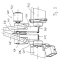
- Fig. 3
- zeigt in einer perspektivischen Ansicht einen Bereich der Anordnung gemäß Fig. 2, nämlich zwei Aktuatoren mit zugehörigen Koppelelementen zur Übertragung von Stellkräften auf ein Betätigungsmodul der Doppelkupplung.
- Fig. 4
- zeigt in den Teilfiguren 4a und 4b eine Alternative zur Anordnung gemäß Fig. 3, wobei Fig. 4a auch zur näheren Erläuterung eine Ausführungsvariante einer erfindungsgemäßen Halteanordnung dient.
- Fig. 5
- ist ein Beispiel zur Erläuterung einer weiteren Ausführungsvariante einer erfindungsgemäßen Halteanordnung.
- Fig. 6
- zeigt die Anordnung der Fig. 5 in einer perspektivischen Ansicht.
- Fig. 7
- zeigt in einer Darstellung entsprechend Fig. 4a bzw. 4b einen weiteren Aktuator mit einer erfindungsgemäßen Halteanordnung, der im Gegensatz zur Halteanordnung der Fig. 4 nicht für ein NORMALERWEISE-OFFEN-Systemverhalten, sondern für ein "NORMALERWEISE-GEHALTEN"-Systemverhalten ausgelegt ist.
- Fig. 8
- zeigt einen erfindungsgemäßen Kraftfahrzeug-Antriebsstrang mit einer dem Getriebe nachgeschalteten Verteil-Kupplungseinrichtung des nasslaufenden Lamellentyps zum Verteilen des Antriebsmoments zwischen Vorder- und Hinterachse in einem Allradfahrzeug.
- Fig. 9
- zeigt eine Ausführungsvariante des Antriebsstrangs gemäß Fig. 8.
Claims (17)
- Kupplungssystem, umfassend eine Reibungskupplungseinrichtung (10) zur Anordnung im Antriebsstrang eines Kraftfahrzeugs mit wenigstens einer gegen in Ausrückrichtung wirkenden mechanischen Rückstellkräften einrückbaren Kupplungsanordnung (12, 32, 34; 14, 32, 36) und eine Betätigungseinrichtung (200, 400) zum Einleiten von im Einrücksinne gegen die Rückstellkräfte wirkenden, auf Betätigungskräften einer Aktuatoranordnung (402, 404) beruhenden Einrückkräften in die Reibungskupplungseinrichtung, um die Kupplungsanordnung im Einrücksinne zu betätigen,
dadurch gekennzeichnet, dass eine der Reibungskupplungseinrichtung oder/und der Kupplungsanordnung oder/und der Betätigungseinrichtung oder/und der Aktuatoranordnung zugeordnete Halteanordnung (430; 430a, 430b; 430c) vorgesehen ist, mittels der die Kupplungsanordnung gegen die Wirkung der Rückstellkräfte unabhängig von der Erzeugung von Betätigungskräften durch die Aktuatoranordnung (402, 404) in einem momentanen Einrückzustand oder einem dem momentanen Einrückzustand zugeordneten Halte-Einrückzustand haltbar ist. - Kupplungssystem nach Anspruch 1,
dadurch gekennzeichnet, dass die Betätigungseinrichtung wenigstens ein der Kupplungsanordnung zugeordnetes Betätigungsglied (222, 224) umfasst, das relativ zu wenigstens einem axial im Wesentlichen feststehenden Stützglied (220) zum Ausüben der Einrückkräfte axial verstellbar ist und zu einem der Kupplungsanordnung zugeordneten Aktuator gehört oder unter Vermittlung eines der Kupplungsanordnung zugeordneten Aktuators (402 bzw. 404) axial relativ zum Stützglied verstellbar ist. - Kupplungssystem nach Anspruch 1 oder 2,
dadurch gekennzeichnet, dass das/ein Betätigungsglied (222 bzw. 224; 512) der Betätigungseinrichtung mit einem um eine Achse dreh- oder schwenkbaren Ausgangsteil (410 bzw. 412) des vorzugsweise elektromotorischen Aktuators (402 bzw. 404) über eine Koppelmechanik bewegungsverkoppelt oder bewegungsverkoppelbar ist. - Kupplungssystem nach einem der Ansprüche 1 bis 3,
dadurch gekennzeichnet, dass die Halteanordnung (430; 430a, 430b; 430c) dafür ausgebildet ist, wenigstens ein Glied (414 bzw. 416) einer von einem/dem Aktuator zu einer miteinander in paarweisen reibschlüssigen Eingriff bringbaren Reibflächenanordnung führenden Betätigungskette, welche das Betätigungsglied (222 bzw. 224) sowie ggf. wenigstens ein Koppelteil (414, 417; 416, 418), insbesondere Eingangsteil oder/und Ausgangsteil, der Koppelmechanik umfasst, in einer momentanen Stellung oder einer der momentanen Stellung zugeordneten, zu dieser benachbarten Haltestellung zu halten. - Kupplungssystem nach Anspruch 4,
dadurch gekennzeichnet, dass das betreffende Glied mit einem zugeordneten Halteglied (434; 434a bzw. 434b; 452) der Halteanordnung in Halteeingriff bringbar ist. - Kupplungssystem nach Anspruch 5,
dadurch gekennzeichnet, dass das betreffende Glied über einen diesem zugeordneten kontinuierlichen Bewegungsbereich in jeder beliebigen momentanen Position durch den Halteeingriff mit dem Halteglied (434; 434a bzw. 434b) haltbar ist. - Kupplungssystem nach Anspruch 5 oder, 6,
dadurch gekennzeichnet, dass wenigstens ein Stellglied (432; 432a bzw. 432b; 458) vorgesehen ist, mittels dem das betreffende Glied und das zugeordnete Halteglied in Halteeingriff bringbar sind, oder/und dass wenigstens ein Stellglied (432') vorgesehen ist, mittels dem der Halteeingriff zwischen dem betreffenden Glied und dem zugeordneten Halteglied aufhebbar ist. - Kupplungssystem nach Anspruch 7,
dadurch gekennzeichnet, dass das betreffende Glied und das zugeordnete Halteglied (434; 434a bzw. 434b; 452) durch das Stellglied (432; 432a bzw. 434b; 458) gegen auf wenigstens eines dieser Glieder wirkende, vorzugsweise von einer Kraftspeicheranordnung (436a bzw. 436b) aufgebrachte mechanische Rückstellkräfte in Halteeingriff bringbar sind und der Halteeingriff auf Grundlage der Rückstellkräfte aufhebbar ist. - Kupplungssystem nach Anspruch 7,
dadurch gekennzeichnet, dass das betreffende Glied und das zugeordnete Halteglied (434) durch von einer mechanischen Einrückanordnung, insbesondere Kraftspeicheranordnung (436') aufgebrachte Einrückkräfte in Halteeingriff bringbar sind und der Halteeingriff durch das Stellglied (432') aufhebbar ist. - Kupplungssystem nach einem der Ansprüche 7 bis 9,
dadurch gekennzeichnet, dass das Stellglied (432; 432a bzw. 434b; 458) wenigstens einen Elektromotor, wenigstens einen elektrisch erregbaren Magneten, wenigstens ein Bimetallelement mit zugeordneter Heizelementanordnung, wenigstens eine Piezoelementanordnung oder wenigstens eine auf Grundlage eines Druckfluids betätigbare Kraftzylinderanordnung zum Erzeugen von Stellkräften aufweist. - Kupplungssystem nach einem der Ansprüche 5 bis 10,
dadurch gekennzeichnet, dass als Aktuator ein Elektromotor (521) mit eingebauter Motorbremse eingesetzt ist, wobei die Motorbremse dafür ausgelegt ist, im stromlosen Zustand des Elektromotors einen momentanen Betätigungszustand des Elektromotors, insbesondere eine momentane Drehstellung eines/des Ausgangsteils (522) des Elektromotors zu halten. - Kupplungssystem nach einem der Ansprüche 5 bis 10,
dadurch gekennzeichnet, dass das oder ein Koppelteil (414 bzw. 416) der Koppelmechanik, insbesondere das Eingangsteil (414 bzw. 416) oder/und das Ausgangsteil der Koppelmechanik, das betreffende Glied ist. - Kupplungssystem nach einem der Ansprüche 5 bis 12,
dadurch gekennzeichnet, dass das Ausgangsteil (410 bzw. 412) des Aktuators und das/ein Eingangsteil (414 bzw. 416) der Koppelmechanik über ein Schnecken- oder Zahnradgetriebe bewegungsverkoppelt sind oder ein eine Bewegungsverkoppelung vorsehendes Schnecken- oder Zahnradgetriebe bilden. - Kupplungssystem nach Anspruch 13,
dadurch gekennzeichnet, dass das als Zahnrad oder Zahnradsegment ausgeführte Eingangsteil (414 bzw. 416) der Koppelmechanik oder ein damit bewegungsverkoppeltes oder bewegungsverkoppelbares Stößelelement zur direkten oder indirekten Ankoppelung am Betätigungsglied (222 bzw. 224) das betreffende Glied ist. - Kupplungssystem nach einem der Ansprüche 1 bis 14,
dadurch gekennzeichnet, dass die Kupplungseinrichtung (10) eine Doppel- oder Mehrfach-Kupplungseinrichtung mit einer einem ersten Getriebezug zugeordneten ersten Kupplungsanordnung (12, 32, 34) und einer einem zweiten Getriebezug zugeordneten zweiten Kupplungsanordnung (14, 32, 36) ist, die unabhängig voneinander mittels eines jeweiligen Aktuators (402 bzw. 404) betätigbar sind. - Kupplungssystem nach Anspruch 15 sowie nach Anspruch 7,
dadurch gekennzeichnet, dass zwei voneinander unabhängige Halteanordnungen (430a, 430b) vorgesehen sind, um die beiden Kupplungsanordnungen (12, 32, 34; 14, 32, 36) unabhängig voneinander sowie unabhängig von der Erzeugung von Betätigungskräften durch den jeweiligen Aktuator (402 bzw. 404) in einem momentanen Einrückzustand oder einem dem momentanen Einrückzustand zugeordneten Halte-Einrückzustand halten zu können. - Halteanordnung zum Halten wenigstens einer Kupplungsanordnung (12, 32, 34; 14, 32, 36) eines Kupplungssystems nach einem der vorhergehenden Ansprüche in einem momentanen Einrückzustand oder einem dem momentanen Einrückzustand zugeordneten Halte-Einrückzustand unabhängig von der Erzeugung von Betätigungskräften durch eine dem Einrücken der Kupplungsanordnung dienenden Aktuatoranordnung (402, 404).
Priority Applications (1)
| Application Number | Priority Date | Filing Date | Title |
|---|---|---|---|
| EP03021283A EP1400716B1 (de) | 2002-09-20 | 2003-09-19 | Kupplungssystem und Halteanordnung zum Halten wenigstens einer Kupplungsanordnung des Kupplungssystems in einem momentanen oder vorgegebenen Einrückzustand |
Applications Claiming Priority (3)
| Application Number | Priority Date | Filing Date | Title |
|---|---|---|---|
| EP02021052A EP1400715A1 (de) | 2002-09-20 | 2002-09-20 | Kupplungssystem und Halteanordnung zum Halten wenigstens einer Kupplungsanordnung des Kupplungssystems in einem momentanen oder vorgegebenen Einrückzustand |
| EP02021052 | 2002-09-20 | ||
| EP03021283A EP1400716B1 (de) | 2002-09-20 | 2003-09-19 | Kupplungssystem und Halteanordnung zum Halten wenigstens einer Kupplungsanordnung des Kupplungssystems in einem momentanen oder vorgegebenen Einrückzustand |
Publications (2)
| Publication Number | Publication Date |
|---|---|
| EP1400716A1 true EP1400716A1 (de) | 2004-03-24 |
| EP1400716B1 EP1400716B1 (de) | 2005-06-22 |
Family
ID=31947894
Family Applications (1)
| Application Number | Title | Priority Date | Filing Date |
|---|---|---|---|
| EP03021283A Expired - Fee Related EP1400716B1 (de) | 2002-09-20 | 2003-09-19 | Kupplungssystem und Halteanordnung zum Halten wenigstens einer Kupplungsanordnung des Kupplungssystems in einem momentanen oder vorgegebenen Einrückzustand |
Country Status (1)
| Country | Link |
|---|---|
| EP (1) | EP1400716B1 (de) |
Cited By (10)
| Publication number | Priority date | Publication date | Assignee | Title |
|---|---|---|---|---|
| DE102004030005A1 (de) * | 2004-06-22 | 2006-01-12 | Zf Friedrichshafen Ag | Elektromechanischer Kupplungsaktuator für ein Fahrzeug mit einem automatisierten oder teilautomatisierten Schaltgetriebe |
| EP1835204A1 (de) | 2006-03-17 | 2007-09-19 | Zf Friedrichshafen Ag | Verfahren zur Steuerung eines automatisierten Doppelkupplungsgetriebes |
| EP1852625A2 (de) * | 2006-05-01 | 2007-11-07 | Globe Motors, Inc. | Bei Systemstromausfall bedienbare Haltevorrichtung mit Doppelfunktion |
| WO2009106538A1 (de) * | 2008-02-29 | 2009-09-03 | Robert Bosch Gmbh | Kupplung sowie hybridantrieb mit kupplung |
| DE102008012894A1 (de) | 2008-03-06 | 2009-09-10 | Zf Friedrichshafen Ag | Betätigungseinrichtung für eine Reibungskupplungseinrichtung und von diesen gebildete Drehmomentübertragungseinrichtung |
| WO2011023563A1 (de) * | 2009-08-31 | 2011-03-03 | Zf Friedrichshafen Ag | Elektromechanische betätigungsanordnung |
| WO2011023566A1 (de) * | 2009-08-31 | 2011-03-03 | Zf Friedrichshafen Ag | Elektromechanische betätigungsanordnung |
| CN110612228A (zh) * | 2017-05-16 | 2019-12-24 | 斯堪尼亚商用车有限公司 | 动力输出装置、动力系和车辆 |
| CN113302416A (zh) * | 2019-01-16 | 2021-08-24 | 舍弗勒技术股份两合公司 | 用于电动车桥的干式双离合器和包括该离合器的电动车桥 |
| WO2023025880A1 (de) * | 2021-08-26 | 2023-03-02 | Zf Friedrichshafen Ag | Kopplungsvorrichtung für eine getriebevorrichtung eines kraftfahrzeugs |
Families Citing this family (1)
| Publication number | Priority date | Publication date | Assignee | Title |
|---|---|---|---|---|
| DE102006030033A1 (de) * | 2006-06-29 | 2008-01-03 | Zf Friedrichshafen Ag | Elektromotorischer Aktuator zum Betätigen einer Kupplung und/oder einer Bremse |
Citations (2)
| Publication number | Priority date | Publication date | Assignee | Title |
|---|---|---|---|---|
| US2991863A (en) * | 1959-06-19 | 1961-07-11 | Int Harvester Co | Hand operated control mechanism for a plurality of clutch assemblies |
| US20010030099A1 (en) * | 2000-04-14 | 2001-10-18 | Mannesmann Sachs Ag | Clutch system with a friction clutch and an actuation device belonging thereto |
-
2003
- 2003-09-19 EP EP03021283A patent/EP1400716B1/de not_active Expired - Fee Related
Patent Citations (2)
| Publication number | Priority date | Publication date | Assignee | Title |
|---|---|---|---|---|
| US2991863A (en) * | 1959-06-19 | 1961-07-11 | Int Harvester Co | Hand operated control mechanism for a plurality of clutch assemblies |
| US20010030099A1 (en) * | 2000-04-14 | 2001-10-18 | Mannesmann Sachs Ag | Clutch system with a friction clutch and an actuation device belonging thereto |
Cited By (21)
| Publication number | Priority date | Publication date | Assignee | Title |
|---|---|---|---|---|
| DE102004030005A1 (de) * | 2004-06-22 | 2006-01-12 | Zf Friedrichshafen Ag | Elektromechanischer Kupplungsaktuator für ein Fahrzeug mit einem automatisierten oder teilautomatisierten Schaltgetriebe |
| DE102004030005B4 (de) * | 2004-06-22 | 2017-05-04 | Zf Friedrichshafen Ag | Elektromechanischer Kupplungsaktuator für ein Fahrzeug mit einem automatisierten oder teilautomatisierten Schaltgetriebe |
| EP1835204A1 (de) | 2006-03-17 | 2007-09-19 | Zf Friedrichshafen Ag | Verfahren zur Steuerung eines automatisierten Doppelkupplungsgetriebes |
| EP1852625A2 (de) * | 2006-05-01 | 2007-11-07 | Globe Motors, Inc. | Bei Systemstromausfall bedienbare Haltevorrichtung mit Doppelfunktion |
| EP1852625A3 (de) * | 2006-05-01 | 2009-04-08 | Globe Motors, Inc. | Bei Systemstromausfall bedienbare Haltevorrichtung mit Doppelfunktion |
| US7828132B2 (en) | 2006-05-01 | 2010-11-09 | Globe Motors, Inc. | Dual function holding device operable under a system power loss condition |
| US8839934B2 (en) | 2008-02-29 | 2014-09-23 | Robert Bosch Gmbh | Clutch and hybrid drive with clutch |
| WO2009106538A1 (de) * | 2008-02-29 | 2009-09-03 | Robert Bosch Gmbh | Kupplung sowie hybridantrieb mit kupplung |
| DE102008012894A1 (de) | 2008-03-06 | 2009-09-10 | Zf Friedrichshafen Ag | Betätigungseinrichtung für eine Reibungskupplungseinrichtung und von diesen gebildete Drehmomentübertragungseinrichtung |
| US8397887B2 (en) | 2008-03-06 | 2013-03-19 | Zf Friedrichshafen Ag | Actuating arrangement for shift elements of a transmission |
| US8534435B2 (en) | 2008-03-06 | 2013-09-17 | Zf Friedrichshafen Ag | Actuating device for a friction clutch device and torque transmission device formed by the same |
| CN102483103A (zh) * | 2009-08-31 | 2012-05-30 | Zf腓德烈斯哈芬股份公司 | 电子机械操纵设施 |
| CN102483158A (zh) * | 2009-08-31 | 2012-05-30 | Zf腓德烈斯哈芬股份公司 | 电子机械操纵设施 |
| US8733526B2 (en) | 2009-08-31 | 2014-05-27 | Zf Friedrichshafen Ag | Electromechanical actuating assembly |
| WO2011023566A1 (de) * | 2009-08-31 | 2011-03-03 | Zf Friedrichshafen Ag | Elektromechanische betätigungsanordnung |
| WO2011023563A1 (de) * | 2009-08-31 | 2011-03-03 | Zf Friedrichshafen Ag | Elektromechanische betätigungsanordnung |
| CN110612228A (zh) * | 2017-05-16 | 2019-12-24 | 斯堪尼亚商用车有限公司 | 动力输出装置、动力系和车辆 |
| CN110612228B (zh) * | 2017-05-16 | 2023-02-17 | 斯堪尼亚商用车有限公司 | 动力输出装置、动力系和车辆 |
| US11667194B2 (en) | 2017-05-16 | 2023-06-06 | Scania Cv Ab | Power take-off arrangement, powertrain, and vehicle |
| CN113302416A (zh) * | 2019-01-16 | 2021-08-24 | 舍弗勒技术股份两合公司 | 用于电动车桥的干式双离合器和包括该离合器的电动车桥 |
| WO2023025880A1 (de) * | 2021-08-26 | 2023-03-02 | Zf Friedrichshafen Ag | Kopplungsvorrichtung für eine getriebevorrichtung eines kraftfahrzeugs |
Also Published As
| Publication number | Publication date |
|---|---|
| EP1400716B1 (de) | 2005-06-22 |
Similar Documents
| Publication | Publication Date | Title |
|---|---|---|
| DE102008063904B4 (de) | Antriebsanordnung | |
| DE102005061268B4 (de) | Reibungskupplung mit Aktuator und Tellerfeder | |
| EP3198160B1 (de) | Zuschaltkupplung für hybriden antriebsstrang mit momentenfühler | |
| EP3405693A1 (de) | Kupplungsanordnung mit einer kugelrampeneinheit und verfahren zum steuern einer kupplungsanordnung | |
| DE102015110186A1 (de) | Stellantrieb für eine Kupplung, insbesondere eines Kraftfahrzeugs | |
| EP1989457A1 (de) | Doppelt wirkende kupplung mit zwei kupplungspaketen und verfahren zur justierung derselben | |
| EP1430230A1 (de) | Mehrfachkupplungsanordnung, insbesondere doppelkupplungsanordnung | |
| EP1400716B1 (de) | Kupplungssystem und Halteanordnung zum Halten wenigstens einer Kupplungsanordnung des Kupplungssystems in einem momentanen oder vorgegebenen Einrückzustand | |
| EP2694846B1 (de) | Vorrichtung zum verändern eines betriebszustandes wenigstens eines schaltelementes | |
| DE102005021901A1 (de) | Vorrichtung und Verfahren zum Einstellen einer Übertragungsfähigkeit eines reibschlüssigen Schaltelementes | |
| DE4140122C2 (de) | Anordnung zur elektromotorischen Betätigung einer reibschlüssigen Verbindung zwischen zwei Getriebegliedern eines Zahnrädergetriebes eines Kraftfahrzeuges | |
| DE102011102329A1 (de) | Doppelkupplung und Verfahren zu deren Steuerung | |
| DE102013201660A1 (de) | Kupplungssystem | |
| EP1178234B1 (de) | Kupplungsanordnung | |
| EP3286446B1 (de) | Kupplungseinrichtung | |
| EP1400715A1 (de) | Kupplungssystem und Halteanordnung zum Halten wenigstens einer Kupplungsanordnung des Kupplungssystems in einem momentanen oder vorgegebenen Einrückzustand | |
| EP3875796B1 (de) | Form- und reibschlüssige kupplung | |
| EP2494231A1 (de) | Betätigungsvorrichtung für kupplungen | |
| DE10236516A1 (de) | Elektromechanische Kupplung und elektromechanisches System | |
| DE102007004754A1 (de) | Wipphebelaktor mit Nachstellvorrichtung | |
| EP1236917A2 (de) | Betätigungseinrichtung für eine Reibungskupplung | |
| DE10234548A1 (de) | Mehrfach-Kupplungsanordnung, insbesondere Doppelkupplungsanordnung | |
| DE102007005773B4 (de) | Wipphebelaktor mit Nachstellvorrichtung | |
| DE102014219745A1 (de) | Nachstelltrieb für eine Nachstelleinrichtung einer Reibkupplung | |
| DE102006009724A1 (de) | Bremsaktuator für Scheibenbremsen |
Legal Events
| Date | Code | Title | Description |
|---|---|---|---|
| PUAI | Public reference made under article 153(3) epc to a published international application that has entered the european phase |
Free format text: ORIGINAL CODE: 0009012 |
|
| AK | Designated contracting states |
Kind code of ref document: A1 Designated state(s): AT BE BG CH CY CZ DE DK EE ES FI FR GB GR HU IE IT LI LU MC NL PT RO SE SI SK TR |
|
| AX | Request for extension of the european patent |
Extension state: AL LT LV MK |
|
| 17P | Request for examination filed |
Effective date: 20040227 |
|
| 17Q | First examination report despatched |
Effective date: 20040423 |
|
| GRAP | Despatch of communication of intention to grant a patent |
Free format text: ORIGINAL CODE: EPIDOSNIGR1 |
|
| AKX | Designation fees paid |
Designated state(s): DE FR GB |
|
| GRAS | Grant fee paid |
Free format text: ORIGINAL CODE: EPIDOSNIGR3 |
|
| GRAL | Information related to payment of fee for publishing/printing deleted |
Free format text: ORIGINAL CODE: EPIDOSDIGR3 |
|
| GRAS | Grant fee paid |
Free format text: ORIGINAL CODE: EPIDOSNIGR3 |
|
| GRAA | (expected) grant |
Free format text: ORIGINAL CODE: 0009210 |
|
| AK | Designated contracting states |
Kind code of ref document: B1 Designated state(s): DE FR GB |
|
| REG | Reference to a national code |
Ref country code: GB Ref legal event code: FG4D Free format text: NOT ENGLISH |
|
| REF | Corresponds to: |
Ref document number: 50300673 Country of ref document: DE Date of ref document: 20050728 Kind code of ref document: P |
|
| GBT | Gb: translation of ep patent filed (gb section 77(6)(a)/1977) |
Effective date: 20050905 |
|
| ET | Fr: translation filed | ||
| PLBE | No opposition filed within time limit |
Free format text: ORIGINAL CODE: 0009261 |
|
| STAA | Information on the status of an ep patent application or granted ep patent |
Free format text: STATUS: NO OPPOSITION FILED WITHIN TIME LIMIT |
|
| 26N | No opposition filed |
Effective date: 20060323 |
|
| PGFP | Annual fee paid to national office [announced via postgrant information from national office to epo] |
Ref country code: GB Payment date: 20080924 Year of fee payment: 6 |
|
| GBPC | Gb: european patent ceased through non-payment of renewal fee |
Effective date: 20090919 |
|
| PG25 | Lapsed in a contracting state [announced via postgrant information from national office to epo] |
Ref country code: GB Free format text: LAPSE BECAUSE OF NON-PAYMENT OF DUE FEES Effective date: 20090919 |
|
| PGFP | Annual fee paid to national office [announced via postgrant information from national office to epo] |
Ref country code: FR Payment date: 20120926 Year of fee payment: 10 |
|
| REG | Reference to a national code |
Ref country code: DE Ref legal event code: R081 Ref document number: 50300673 Country of ref document: DE Owner name: ZF FRIEDRICHSHAFEN AG, DE Free format text: FORMER OWNER: ZF SACHS AG, 97424 SCHWEINFURT, DE Effective date: 20130326 |
|
| REG | Reference to a national code |
Ref country code: FR Ref legal event code: ST Effective date: 20140530 |
|
| PG25 | Lapsed in a contracting state [announced via postgrant information from national office to epo] |
Ref country code: FR Free format text: LAPSE BECAUSE OF NON-PAYMENT OF DUE FEES Effective date: 20130930 |
|
| PGFP | Annual fee paid to national office [announced via postgrant information from national office to epo] |
Ref country code: DE Payment date: 20140917 Year of fee payment: 12 |
|
| REG | Reference to a national code |
Ref country code: DE Ref legal event code: R119 Ref document number: 50300673 Country of ref document: DE |
|
| PG25 | Lapsed in a contracting state [announced via postgrant information from national office to epo] |
Ref country code: DE Free format text: LAPSE BECAUSE OF NON-PAYMENT OF DUE FEES Effective date: 20160401 |