EP1400701A2 - Wasserpumpe - Google Patents
Wasserpumpe Download PDFInfo
- Publication number
- EP1400701A2 EP1400701A2 EP03020501A EP03020501A EP1400701A2 EP 1400701 A2 EP1400701 A2 EP 1400701A2 EP 03020501 A EP03020501 A EP 03020501A EP 03020501 A EP03020501 A EP 03020501A EP 1400701 A2 EP1400701 A2 EP 1400701A2
- Authority
- EP
- European Patent Office
- Prior art keywords
- pump
- pump shaft
- impeller
- pump body
- annular member
- Prior art date
- Legal status (The legal status is an assumption and is not a legal conclusion. Google has not performed a legal analysis and makes no representation as to the accuracy of the status listed.)
- Granted
Links
Images



Classifications
-
- F—MECHANICAL ENGINEERING; LIGHTING; HEATING; WEAPONS; BLASTING
- F04—POSITIVE - DISPLACEMENT MACHINES FOR LIQUIDS; PUMPS FOR LIQUIDS OR ELASTIC FLUIDS
- F04D—NON-POSITIVE-DISPLACEMENT PUMPS
- F04D29/00—Details, component parts, or accessories
- F04D29/60—Mounting; Assembling; Disassembling
- F04D29/62—Mounting; Assembling; Disassembling of radial or helico-centrifugal pumps
- F04D29/628—Mounting; Assembling; Disassembling of radial or helico-centrifugal pumps especially adapted for liquid pumps
-
- F—MECHANICAL ENGINEERING; LIGHTING; HEATING; WEAPONS; BLASTING
- F04—POSITIVE - DISPLACEMENT MACHINES FOR LIQUIDS; PUMPS FOR LIQUIDS OR ELASTIC FLUIDS
- F04D—NON-POSITIVE-DISPLACEMENT PUMPS
- F04D29/00—Details, component parts, or accessories
- F04D29/08—Sealings
- F04D29/10—Shaft sealings
- F04D29/12—Shaft sealings using sealing-rings
- F04D29/126—Shaft sealings using sealing-rings especially adapted for liquid pumps
-
- Y—GENERAL TAGGING OF NEW TECHNOLOGICAL DEVELOPMENTS; GENERAL TAGGING OF CROSS-SECTIONAL TECHNOLOGIES SPANNING OVER SEVERAL SECTIONS OF THE IPC; TECHNICAL SUBJECTS COVERED BY FORMER USPC CROSS-REFERENCE ART COLLECTIONS [XRACs] AND DIGESTS
- Y10—TECHNICAL SUBJECTS COVERED BY FORMER USPC
- Y10S—TECHNICAL SUBJECTS COVERED BY FORMER USPC CROSS-REFERENCE ART COLLECTIONS [XRACs] AND DIGESTS
- Y10S415/00—Rotary kinetic fluid motors or pumps
- Y10S415/915—Pump or portion thereof by casting or molding
Definitions
- the present invention relates to a water pump, and particularly relates to a water pump which circulates cooling water of a water-cooled internal combustion engine within the internal combustion engine.
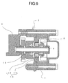
- a water pump 2 is disposed to perform cooling of the internal combustion engine 1.
- the water pump 2 is disposed integrally to a crank case 3 of the internal combustion engine 1, and driven by a crank shaft 4 which is accommodated in the crank case 3.
- cooling water which is cooled by a radiator, not shown in figures, is led to a water jacket 6 in a cylinder block 5 of the internal combustion engine 1 for example, and the cooling is performed.
- the water pump 2 comprises a pump body 7, a pump shaft 9 which is rotatably supported by the pump body 7 in a piercing state and to which an impeller 8 is attached at one end portion, and a mechanical seal 10 which is elastically disposed between the side of the pump shaft 9 where the impeller 8 is attached and the pump body 7.
- the mechanical seal 10 is constructed by a seal member 11 and a spring 12 which elastically urges the seal member 11 towards the impeller 8.
- a dislodging prevention pin 13 is disposed to the pump shaft 9 opposite to the side where the impeller 8 is attached, being in contact with the pump body 7, so as to receive force in the thrust direction generated by the mechanical seal 10.
- the pump shaft 9 has a two-point mounting structure that a midway portion is rotatably supported by the pump body 7, and an end portion is rotatably supported by the crank case 3 to which the pump body 7 is attached.
- Fig. 1 of Japanese Utility-model Kokoku H6-31197 discloses this structure.
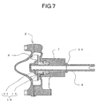
- Fig. 7 shows another structure example of the water pump 2 of the related art.
- a flange 14 is integrally formed at the midway portion of the pump shaft 9 so as to receive the force in the thrust direction generated by the mechanical seal 10 and prevent dislodging of the pump shaft 9.
- Fig. 1 of Japanese Patent Laid-open 2000-87744 discloses this structure.
- the impeller 8 has to be attached to the pump shaft 9 after the pump shaft 9 is inserted to the pump body 7. Therefore, the impeller 8 cannot be assembled with the pump shaft 9 in advance.
- the present invention was devised in the light of the abovementioned problems.
- the object is to provide a water pump which machining accuracy and assembling accuracy can be easily improved.
- the water pump of claim 1 of the present invention comprises, a pump body, a pump shaft which is rotatably supported by the pump body in a piercing state and to which an impeller is attached at one end portion, a mechanical seal which is disposed elastically via urging means between the pump body and the end portion of the pump shaft where the impeller is attached, and an engage mechanism which is disposed between the pump body and the end portion of the pump shaft opposite to the side where the impeller is attached, while engaging the pump shaft to the pump body against the urging force of the urging means, wherein the engage mechanism comprises an annular member which is rotatably fitted to the pump shaft while contacting the pump body, and a cylindrical engage pin which pierces the pump shaft in the diameter direction while sandwiching the annular member with the pump body.
- the annular member of claim 1 is formed so that the cross section in the diameter direction is roughly circular.
- the annular member of claim 1 is formed so that the cross section in the diameter direction is plate-shaped, and an annular flange is formed at the circumference portion so as to face the end face of the engage pin.
- the urging means of claim 3 is formed so that the possible expansion-and-contraction stroke is at least equal to the height of the flange.
- the impeller of any one of claim 1 through 4 is attached integrally to the pump shaft.
- the impeller of claim 5 is integrated with the pump shaft by insert molding.
- the pump shaft is supported at one point so that the alignment to the pump body can be easily performed.
- the grinding of the outer face can be easily performed and the accurate machining can be obtained.
- smooth rotation of the pump shaft can be ensured.
- a simple machining method such as centerless grinding, can be adopted. This method, as well as the abovementioned easiness of the alignment, enables the reduction of the machining cost.
- the water pump shown by numeral 20 in Fig. 1 basically comprises, a pump body 21 which is attached to the crank case 3, a pump shaft 23 which is rotatably supported by the pump body 21 in a piercing state and to which an impeller 22 is attached at one end portion, a mechanical seal 24 which is disposed elastically via urging means between the pump body 21 and the end portion of the pump shaft 23 where the impeller 22 is attached, and an engage mechanism 25 which is disposed between the pump body 21 and the end portion of the pump shaft 23 opposite to the side where the impeller 22 is attached, while engaging the pump shaft 23 to the pump body 21 against the urging force of the urging means, wherein the engage mechanism 25 comprises an annular member 26 which is rotatably fitted to the pump shaft 23 while contacting the pump body 21, and a cylindrical engage pin 27 which pierces the pump shaft 23 in the diameter direction while sandwiching the annular member 26 with the pump body 21.
- the mechanical seal 24 is constructed by a seal member 28 which is pressed to contact the side face of a rotating center portion of the impeller 22, and an urging means 30 having a spring etc. which is disposed between the seal member 28 and a spring seat 29 engaged in the pump body 21 so that the seal member 28 is pressed to contact the impeller 22 elastically.
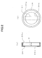
- the annular member 26 is formed so that the cross section in the diameter direction is plate-shaped, and annular flange 26a is formed at its circumference portion so as to face the end face of the engage pin 27. As a whole, it is formed like a bowl-shape, and a penetrating hole 26b to which the pump shaft 23 is inserted is formed around its center.
- the inner diameter of the flange 26a is larger than the length of the engage pin 27, so that the engage pin 27 can be housed in the flange 26a.
- a piercing hole 23a is formed at the pump shaft 23 in the diameter direction to which the engage pin 27 is fitted.
- the urging means 30 is constructed so that the amount of the expansion-and-contraction stroke is equal to or larger than the height H of the flange 26a.
- the piercing hole 23a which is formed at the pump shaft 23 positions outside the flange 26a of the annular member 26 which is in the state of being contacted with the pump body 21.
- the impeller 22 is formed of synthetic resin, and attached integrally to the one end portion of the pump shaft 23 by insert molding.
- the seal member 28 of the mechanical seal 24 is attached to the impeller 22.
- the urging means 30 of the mechanical seal 24 is attached to one end portion of the inserted part of the pump body 21 to which the pump shaft 23 is inserted.
- the pump shaft 23 with the impeller 22 and the seal member 28 attached is inserted through the urging means 30 of the mechanical seal 24, from the end portion where the impeller 22 is not attached.
- the end portion protrudes from the opposite side of the pump body 21, and the annular member 26 is fitted to the end portion, as shown by the arrow X in Fig. 3.
- the pump shaft 23 is further pressed into the pump body 21, so that the urging means 30 constructing the mechanical seal 24 is fully contracted, while the annular member 26 is contacted to the pump body 21.
- the piercing hole 23a formed at the pump shaft 23 positions at the outer side of the flange 26a of the annular member 26.
- the engage pin 27 is fitted in the piercing hole 23a of the pump shaft 23. After adjusting the engage pin 27 to position inside the flange 26a of the annular member 26, the pressing force to the pump shaft 23 is released.
- the pump shaft 23 and the impeller 22 are moved by the urging means 30 constructing mechanical seal 24, in the direction where the impeller 22 is apart from the pump body 21. Then, the engage pin 27 contacts the annular member 26 while being housed in the flange 26a of the annular member 26.
- the pump shaft 23 is supported at one point. Therefore, the alignment is easily performed.
- the pump shaft 23 has no part projecting outside in the whole range in the diameter direction. Therefore, the grinding of the outer face is easily performed, and accurate machining can be obtained.
- the pump shaft 23 has no part projecting outside in the diameter direction, a simple machining method, such as centerless grinding, can be adopted to reduce the manufacturing cost.
- the pump shaft 23 can be attached to the pump body 21 only by being inserted from one direction in the axis direction, it is possible to be assembled in the state that the impeller 22 is attached to the pump shaft 23 at the opposite side of the end portion which is inserted to the pump body 21.
- the impeller 22 can be assembled with the pump shaft 23 in advance, and the assembling performance of the water pump 20 is improved as a whole.
- each constructing member of the abovementioned embodiment is just examples, and can be modified variously in accordance with design requirement etc.
- the annular member 26 is not limited to an integrally formed bowl-shaped washer. The same effects can be obtained even when the plate portion which contacts the engage pin 27 and the flange 26a which covers the end portion of the engage pin 27 are formed separately.
- the annular member 31 to contact the engage pin 27 can be formed so that the cross section in the diameter direction is roughly arc-shaped.
- the flange 31a can be formed at the circumference of the annular member 31.
Landscapes
- Engineering & Computer Science (AREA)
- Mechanical Engineering (AREA)
- General Engineering & Computer Science (AREA)
- Structures Of Non-Positive Displacement Pumps (AREA)
- Mechanical Sealing (AREA)
Applications Claiming Priority (2)
| Application Number | Priority Date | Filing Date | Title |
|---|---|---|---|
| JP2002271439A JP4279528B2 (ja) | 2002-09-18 | 2002-09-18 | ウォータポンプ |
| JP2002271439 | 2002-09-18 |
Publications (3)
| Publication Number | Publication Date |
|---|---|
| EP1400701A2 true EP1400701A2 (de) | 2004-03-24 |
| EP1400701A3 EP1400701A3 (de) | 2006-06-07 |
| EP1400701B1 EP1400701B1 (de) | 2015-07-22 |
Family
ID=31944549
Family Applications (1)
| Application Number | Title | Priority Date | Filing Date |
|---|---|---|---|
| EP03020501.7A Expired - Lifetime EP1400701B1 (de) | 2002-09-18 | 2003-09-15 | Wasserpumpe |
Country Status (3)
| Country | Link |
|---|---|
| US (1) | US6896486B2 (de) |
| EP (1) | EP1400701B1 (de) |
| JP (1) | JP4279528B2 (de) |
Cited By (1)
| Publication number | Priority date | Publication date | Assignee | Title |
|---|---|---|---|---|
| CN105351214A (zh) * | 2015-11-05 | 2016-02-24 | 安徽盛唐泵阀制造有限公司 | 一种流体输送泵 |
Families Citing this family (2)
| Publication number | Priority date | Publication date | Assignee | Title |
|---|---|---|---|---|
| KR20040022451A (ko) * | 2001-07-16 | 2004-03-12 | 유킹 렌 | 임베디드 소프트웨어 업데이트 시스템 |
| US7249556B2 (en) * | 2004-11-29 | 2007-07-31 | Haldex Brake Corporation | Compressor with fortified piston channel |
Citations (1)
| Publication number | Priority date | Publication date | Assignee | Title |
|---|---|---|---|---|
| US4746270A (en) | 1987-07-20 | 1988-05-24 | Deco-Grand, Inc. | Engine water pump assembly and method of making same |
Family Cites Families (7)
| Publication number | Priority date | Publication date | Assignee | Title |
|---|---|---|---|---|
| US2170134A (en) * | 1936-10-26 | 1939-08-22 | Zeno E Flick | Bearing seal |
| US2842062A (en) * | 1951-10-31 | 1958-07-08 | Pratt & Whitney Co Inc | Vortex pump |
| US2842063A (en) * | 1955-06-24 | 1958-07-08 | American Motors Corp | Water pump mounting |
| US4784088A (en) * | 1985-12-05 | 1988-11-15 | Kawasaki Jukogyo Kabushiki Kaisha | Drive device for coolant pumps |
| JPS63191236U (de) * | 1987-05-29 | 1988-12-09 | ||
| JPH0631197A (ja) | 1992-07-21 | 1994-02-08 | Hitachi Zosen Corp | 金属の回収装置 |
| JP4080610B2 (ja) | 1998-09-14 | 2008-04-23 | 本田技研工業株式会社 | エンジンの水ポンプ構造 |
-
2002
- 2002-09-18 JP JP2002271439A patent/JP4279528B2/ja not_active Expired - Fee Related
-
2003
- 2003-09-10 US US10/658,426 patent/US6896486B2/en not_active Expired - Fee Related
- 2003-09-15 EP EP03020501.7A patent/EP1400701B1/de not_active Expired - Lifetime
Patent Citations (1)
| Publication number | Priority date | Publication date | Assignee | Title |
|---|---|---|---|---|
| US4746270A (en) | 1987-07-20 | 1988-05-24 | Deco-Grand, Inc. | Engine water pump assembly and method of making same |
Cited By (1)
| Publication number | Priority date | Publication date | Assignee | Title |
|---|---|---|---|---|
| CN105351214A (zh) * | 2015-11-05 | 2016-02-24 | 安徽盛唐泵阀制造有限公司 | 一种流体输送泵 |
Also Published As
| Publication number | Publication date |
|---|---|
| US20040086402A1 (en) | 2004-05-06 |
| US6896486B2 (en) | 2005-05-24 |
| EP1400701B1 (de) | 2015-07-22 |
| EP1400701A3 (de) | 2006-06-07 |
| JP4279528B2 (ja) | 2009-06-17 |
| JP2004108238A (ja) | 2004-04-08 |
Similar Documents
| Publication | Publication Date | Title |
|---|---|---|
| US6862946B2 (en) | Geared motor comprising position sensor | |
| JP2003003927A (ja) | 燃料噴射ポンプ | |
| US6120403A (en) | Pivotal support structure for oscillating member | |
| EP1701020B1 (de) | Drosselvorrichtung und für die drosselvorrichtung verwendeter motor | |
| US7600920B2 (en) | Bearing holding structure for motor | |
| US6896486B2 (en) | Water pump | |
| EP0289958A2 (de) | Wasserpumpe | |
| US6799954B2 (en) | Tappet turning-prevention structure for fuel supply apparatus | |
| JP4539383B2 (ja) | 動力伝達装置のコントロールユニット取付構造 | |
| JP6096451B2 (ja) | ウォータポンプ | |
| US7898132B2 (en) | Motor assembly | |
| US20210372529A1 (en) | Separate valve seating | |
| JP2835503B2 (ja) | ギヤセット | |
| CN108631476B (zh) | 步进电机 | |
| KR19980080780A (ko) | 자석발전기의 회전자 | |
| US20190128416A1 (en) | Shift device of transmission | |
| US20040211391A1 (en) | Throttle valve body | |
| US9851123B2 (en) | Flap device for an internal combustion engine or an electric vehicle | |
| EP3708771B1 (de) | Pumpvorrichtung | |
| JP5063393B2 (ja) | オイルレベルゲージの案内管の取付構造 | |
| CN101273196A (zh) | 起动电动机 | |
| JP2025147887A (ja) | ポンプの取付構造 | |
| JP3577381B2 (ja) | ベーンポンプの駆動軸支持構造 | |
| US5318153A (en) | Oil pump | |
| KR100435947B1 (ko) | 오일 펌프 커버에 로터실이 형성된 오일펌프 |
Legal Events
| Date | Code | Title | Description |
|---|---|---|---|
| PUAI | Public reference made under article 153(3) epc to a published international application that has entered the european phase |
Free format text: ORIGINAL CODE: 0009012 |
|
| AK | Designated contracting states |
Kind code of ref document: A2 Designated state(s): AT BE BG CH CY CZ DE DK EE ES FI FR GB GR HU IE IT LI LU MC NL PT RO SE SI SK TR |
|
| AX | Request for extension of the european patent |
Extension state: AL LT LV MK |
|
| PUAL | Search report despatched |
Free format text: ORIGINAL CODE: 0009013 |
|
| AK | Designated contracting states |
Kind code of ref document: A3 Designated state(s): AT BE BG CH CY CZ DE DK EE ES FI FR GB GR HU IE IT LI LU MC NL PT RO SE SI SK TR |
|
| AX | Request for extension of the european patent |
Extension state: AL LT LV MK |
|
| 17P | Request for examination filed |
Effective date: 20060602 |
|
| AKX | Designation fees paid |
Designated state(s): FR GB IT |
|
| REG | Reference to a national code |
Ref country code: DE Ref legal event code: 8566 |
|
| 17Q | First examination report despatched |
Effective date: 20090727 |
|
| GRAP | Despatch of communication of intention to grant a patent |
Free format text: ORIGINAL CODE: EPIDOSNIGR1 |
|
| INTG | Intention to grant announced |
Effective date: 20150211 |
|
| GRAS | Grant fee paid |
Free format text: ORIGINAL CODE: EPIDOSNIGR3 |
|
| GRAA | (expected) grant |
Free format text: ORIGINAL CODE: 0009210 |
|
| AK | Designated contracting states |
Kind code of ref document: B1 Designated state(s): FR GB IT |
|
| REG | Reference to a national code |
Ref country code: GB Ref legal event code: FG4D |
|
| RIN1 | Information on inventor provided before grant (corrected) |
Inventor name: SHICHI, MAKOTO Inventor name: TAKEHANA, NORIO Inventor name: NAIKI, TAKEHIKO |
|
| PLBE | No opposition filed within time limit |
Free format text: ORIGINAL CODE: 0009261 |
|
| STAA | Information on the status of an ep patent application or granted ep patent |
Free format text: STATUS: NO OPPOSITION FILED WITHIN TIME LIMIT |
|
| 26N | No opposition filed |
Effective date: 20160425 |
|
| REG | Reference to a national code |
Ref country code: FR Ref legal event code: PLFP Year of fee payment: 14 |
|
| PGFP | Annual fee paid to national office [announced via postgrant information from national office to epo] |
Ref country code: GB Payment date: 20160914 Year of fee payment: 14 Ref country code: IT Payment date: 20160921 Year of fee payment: 14 |
|
| PGFP | Annual fee paid to national office [announced via postgrant information from national office to epo] |
Ref country code: FR Payment date: 20160816 Year of fee payment: 14 |
|
| GBPC | Gb: european patent ceased through non-payment of renewal fee |
Effective date: 20170915 |
|
| REG | Reference to a national code |
Ref country code: FR Ref legal event code: ST Effective date: 20180531 |
|
| PG25 | Lapsed in a contracting state [announced via postgrant information from national office to epo] |
Ref country code: GB Free format text: LAPSE BECAUSE OF NON-PAYMENT OF DUE FEES Effective date: 20170915 |
|
| PG25 | Lapsed in a contracting state [announced via postgrant information from national office to epo] |
Ref country code: FR Free format text: LAPSE BECAUSE OF NON-PAYMENT OF DUE FEES Effective date: 20171002 Ref country code: IT Free format text: LAPSE BECAUSE OF NON-PAYMENT OF DUE FEES Effective date: 20170915 |