EP1400647B1 - Partition wall element with a top supporting device and a bottom floor guide - Google Patents
Partition wall element with a top supporting device and a bottom floor guide Download PDFInfo
- Publication number
- EP1400647B1 EP1400647B1 EP03021257A EP03021257A EP1400647B1 EP 1400647 B1 EP1400647 B1 EP 1400647B1 EP 03021257 A EP03021257 A EP 03021257A EP 03021257 A EP03021257 A EP 03021257A EP 1400647 B1 EP1400647 B1 EP 1400647B1
- Authority
- EP
- European Patent Office
- Prior art keywords
- partition wall
- wall component
- profile
- profile leg
- leg
- Prior art date
- Legal status (The legal status is an assumption and is not a legal conclusion. Google has not performed a legal analysis and makes no representation as to the accuracy of the status listed.)
- Expired - Lifetime
Links
- 238000005192 partition Methods 0.000 title claims abstract description 57
- 125000006850 spacer group Chemical group 0.000 claims description 8
- 210000002414 leg Anatomy 0.000 description 41
- 239000011521 glass Substances 0.000 description 18
- 238000005553 drilling Methods 0.000 description 3
- 238000004519 manufacturing process Methods 0.000 description 3
- 238000006073 displacement reaction Methods 0.000 description 2
- 210000003414 extremity Anatomy 0.000 description 2
- 230000015572 biosynthetic process Effects 0.000 description 1
- 238000010276 construction Methods 0.000 description 1
- 230000003993 interaction Effects 0.000 description 1
- 239000000463 material Substances 0.000 description 1
- 238000005096 rolling process Methods 0.000 description 1
- 238000000638 solvent extraction Methods 0.000 description 1
- 210000000689 upper leg Anatomy 0.000 description 1
Images


Classifications
-
- E—FIXED CONSTRUCTIONS
- E05—LOCKS; KEYS; WINDOW OR DOOR FITTINGS; SAFES
- E05D—HINGES OR SUSPENSION DEVICES FOR DOORS, WINDOWS OR WINGS
- E05D15/00—Suspension arrangements for wings
- E05D15/06—Suspension arrangements for wings for wings sliding horizontally more or less in their own plane
- E05D15/0621—Details, e.g. suspension or supporting guides
- E05D15/0626—Details, e.g. suspension or supporting guides for wings suspended at the top
- E05D15/063—Details, e.g. suspension or supporting guides for wings suspended at the top on wheels with fixed axis
- E05D15/0634—Details, e.g. suspension or supporting guides for wings suspended at the top on wheels with fixed axis with height adjustment
-
- E—FIXED CONSTRUCTIONS
- E05—LOCKS; KEYS; WINDOW OR DOOR FITTINGS; SAFES
- E05D—HINGES OR SUSPENSION DEVICES FOR DOORS, WINDOWS OR WINGS
- E05D5/00—Construction of single parts, e.g. the parts for attachment
- E05D5/02—Parts for attachment, e.g. flaps
- E05D5/0246—Parts for attachment, e.g. flaps for attachment to glass panels
- E05D2005/0253—Parts for attachment, e.g. flaps for attachment to glass panels the panels having conical or stepped recesses
-
- E—FIXED CONSTRUCTIONS
- E05—LOCKS; KEYS; WINDOW OR DOOR FITTINGS; SAFES
- E05D—HINGES OR SUSPENSION DEVICES FOR DOORS, WINDOWS OR WINGS
- E05D5/00—Construction of single parts, e.g. the parts for attachment
- E05D5/02—Parts for attachment, e.g. flaps
- E05D5/0246—Parts for attachment, e.g. flaps for attachment to glass panels
-
- E—FIXED CONSTRUCTIONS
- E05—LOCKS; KEYS; WINDOW OR DOOR FITTINGS; SAFES
- E05Y—INDEXING SCHEME RELATING TO HINGES OR OTHER SUSPENSION DEVICES FOR DOORS, WINDOWS OR WINGS AND DEVICES FOR MOVING WINGS INTO OPEN OR CLOSED POSITION, CHECKS FOR WINGS AND WING FITTINGS NOT OTHERWISE PROVIDED FOR, CONCERNED WITH THE FUNCTIONING OF THE WING
- E05Y2800/00—Details, accessories and auxiliary operations not otherwise provided for
- E05Y2800/67—Materials; Strength alteration thereof
- E05Y2800/672—Glass
-
- E—FIXED CONSTRUCTIONS
- E05—LOCKS; KEYS; WINDOW OR DOOR FITTINGS; SAFES
- E05Y—INDEXING SCHEME RELATING TO HINGES OR OTHER SUSPENSION DEVICES FOR DOORS, WINDOWS OR WINGS AND DEVICES FOR MOVING WINGS INTO OPEN OR CLOSED POSITION, CHECKS FOR WINGS AND WING FITTINGS NOT OTHERWISE PROVIDED FOR, CONCERNED WITH THE FUNCTIONING OF THE WING
- E05Y2900/00—Application of doors, windows, wings or fittings thereof
- E05Y2900/10—Application of doors, windows, wings or fittings thereof for buildings or parts thereof
- E05Y2900/13—Application of doors, windows, wings or fittings thereof for buildings or parts thereof characterised by the type of wing
- E05Y2900/132—Doors
-
- E—FIXED CONSTRUCTIONS
- E05—LOCKS; KEYS; WINDOW OR DOOR FITTINGS; SAFES
- E05Y—INDEXING SCHEME RELATING TO HINGES OR OTHER SUSPENSION DEVICES FOR DOORS, WINDOWS OR WINGS AND DEVICES FOR MOVING WINGS INTO OPEN OR CLOSED POSITION, CHECKS FOR WINGS AND WING FITTINGS NOT OTHERWISE PROVIDED FOR, CONCERNED WITH THE FUNCTIONING OF THE WING
- E05Y2900/00—Application of doors, windows, wings or fittings thereof
- E05Y2900/10—Application of doors, windows, wings or fittings thereof for buildings or parts thereof
- E05Y2900/13—Application of doors, windows, wings or fittings thereof for buildings or parts thereof characterised by the type of wing
- E05Y2900/148—Windows
- E05Y2900/15—Balcony glazing
Definitions
- the invention relates to a means of an upper support device to a Guide rail slidably guided and by means of a lower floor guide positively guided partition element, wherein the support device and the floor guide each having a vertically extending, the Partition element indirectly or directly adjacent, with the Partition element screwed laschenförmigen profile legs of a Have support profiles or a floor guide profile and the Carrying device with a horizontal profile leg and one on the horizontal profile leg adjoining vertical profile leg the upper end edge of the partition wall element and the bottom guide with a horizontal profile leg and one on the horizontal profile leg subsequent vertical profile leg the lower end edge the partition wall element engages.
- Partition wall elements of the aforementioned type are usually made Glass panes, which are combined to form full-coverage glass fronts or at open partition can be stored in a storage space.
- the attachment Gias disks on suitable support elements are made regularly via holes arranged in the glass pane.
- Fasteners or fasteners of a certain are subject to manufacturing tolerance, there is regularly the problem the hole in the glass with the axis of the fastener or bring clamping element in an aligned cover.
- the respective connection between the glass pane and the Befest Trentsoder Support element allows this, then one deviates here on the mounting or carrier element, d. H. the required tolerance compensation is placed in the mounting or support element.
- DE 38 14 535 A1 relates to a running device for a hanging Sliding wall, in which the sliding wall element by means of a supporting bolt attached to a carriage. The connection of the support bolt on Sliding wall element via a clamped onto the sliding wall element Profile strip.
- US Pat. No. 4,905,345 is concerned with one on a guide rail rolling door, with the door over vertically extending tabs is hung on the carriage.
- a device designed for the lining of a balcony, disclosed in US Patent 5 088 236.
- Das upper end edge of the partition wall element substantially U-shaped or L-shaped embracing support profile or the lower end of the in the same way encompassing floor guide profile lies with its horizontal Profile legs recognizable directly to the respective front edge.
- the connection of the support device or the floor guide with the Partition element thus leaves no, due to the prescribed Manufacturing tolerances, required tolerance compensation to.
- the invention solves the problem set with the features of claim 1.
- the invention proposes that between the pressure piece and the upper end edge and / or lower end edge the partition element an edge protection is arranged.
- the hole in the tab-shaped profile leg as vertical Slot is formed, wherein the slot in the manner of a keyhole (Bundbart) formed with a narrower and a wider area is and the retaining pin of the point holder has a bolt head, such that it is plugged through the wider area and the the narrower area delimiting section behind.
- the aforementioned Embodiment allows the above-described longitudinal displacement of strap-shaped profile leg with simultaneous subsequent non-positive Connection of the profile leg with the partition element.
- the horizontal profile leg of the floor guide profile two mutually parallel threaded holes for receiving clamping screws and one between the threaded holes arranged hole for receiving a in or on Having a bottom rail forcibly guided floor guide element.
- the floor guide element itself can be designed as desired.
- a support device and a floor guide proposed for a partition element by means of which at more reliable Connection between the support device and the floor guide with the partition element a simple, heavy-duty adjustment of Partition element, in particular a glass, the height is possible.
- Partition element in particular a glass
- An upper end edge of the partition wall element 1 is denoted by 11 and a lower end edge by 14.
- the support profile 7 of the support device 2 of Figure 2 consists essentially from a tab-shaped profile leg 6, the - preferably in one piece - Is connected to a horizontal profile leg 9.
- the horizontal one Profile limb 9 overlaps the upper end edge 11 of FIG. 2 Not shown partition wall element 1.
- To the horizontal profile leg 9 is followed by a vertical profile leg 10, which - as in FIG 4 shows - the partition wall element 1 engages laterally.
- the kind of one Carrying head trained horizontal profile leg 9 has two parallel mutually extending distanced threaded holes 17, in the clamping screws Border 18. Between the threaded holes 17 is a larger bore 19 for receiving the support pin shown in Figure 1 20 arranged.
- the clamping screws 18 act on a pressure piece 15, which is formed as a pressure plate 16, and further on a, in particular in glass plates, advantageous edge protection 21, the in a groove 36 of the horizontal profile leg 9 is guided.
- a keyhole-like bore 25 which is the connection a generally designated 24 point holder is used.
- the Point holder 24 a retaining pin 23 with a bolt head 30, the so is shaped to be the wider area 29 of the vertical slot 27 trained bore 25 can pass through and, as Figure 4 recognize leaves, sunk at the narrower portion 28 of the vertical Langloches 27 can support.
- the dot holder 24 also has in known Make a cone nut 35, a conical glass guard 34th and a disk-shaped glass guard 33. As shown in FIG. 4.
- a Center longitudinal axis of the retaining bolt 23 is denoted by 26, so that the Retaining pin 23 aligned holes 25 in the spacer 22, the glass protection 33, the glass guard 34 and the cone nut 35 can pass through, as can be seen in particular from Figure 5.
- a floor guide profile 8 corresponds to a floor guide 4 according to FIGS. 6 to 9 essentially the support profile 7 of the support device 2 with the Deviation that between the threaded holes 17 has a bore 31st is arranged, which is the inclusion of a bottom guide element 32nd serves.
- the horizontal profile leg 12 of the floor guide profile 8 is less strong than the horizontal with respect to its thigh thickness Profile leg 9 of the support device 2, because on the horizontal Profile leg 12 lower forces act.
- the support device 2 closes on the horizontal profile leg 12 also a vertical profile leg 13, so that too here a groove-like receptacle for the lower end edge 14 of the partition wall element 1 is formed.
Abstract
Description
Die Erfindung betrifft ein mittels einer oberen Tragvorrichtung an einer Führungsschiene verschiebbar geführtes und mittels einer unteren Bodenführung zwangsgeführtes Trennwandelement, wobei die Tragvorrichtung und die Bodenführung jeweils einen sich vertikal erstreckenden, dem Trennwandelement mittelbar oder unmittelbar anliegenden, mit dem Trennwandelement verschraubbaren laschenförmigen Profilschenkel eines Tragprofiles bzw. eines Bodenführungsprofiles aufweisen und die Tragvorrichtung mit einem horizontalen Profilschenkel und einem an dem horizontalen Profilschenkel anschließenden vertikalen Profilschenkel die obere Stirnkante des Trennwandelementes und die Bodenführung mit einem horizontalen Profilschenkel und einem an dem horizontalen Profilschenkel anschließenden vertikalen Profilschenkel die untere Stimkante des Trennwandelementes umgreift.The invention relates to a means of an upper support device to a Guide rail slidably guided and by means of a lower floor guide positively guided partition element, wherein the support device and the floor guide each having a vertically extending, the Partition element indirectly or directly adjacent, with the Partition element screwed laschenförmigen profile legs of a Have support profiles or a floor guide profile and the Carrying device with a horizontal profile leg and one on the horizontal profile leg adjoining vertical profile leg the upper end edge of the partition wall element and the bottom guide with a horizontal profile leg and one on the horizontal profile leg subsequent vertical profile leg the lower end edge the partition wall element engages.
Trennwandelemente der vorgenannten Art bestehen im Regelfall aus Glasscheiben, die zu flächendeckenden Glasfronten vereinigt oder bei offener Trennwand in einem Stauraum gelagert werden können. Die Befestigung von Giasscheiben an geeigneten Trägerelementen erfolgt regelmäßig über in der Glasscheibe angeordnete Bohrungen. Da die vorgenannten Bohrungen ebenso wie die den sie einfassenden oder sie durchfassenden Befestigungselemente oder Verbindungselemente einer gewissen Fertigungstoleranz unterliegen, besteht regelmäßig die Problematik, die Bohrung in der Glasscheibe mit der Achse des Befestigungselementes oder Klemmelementes in eine fluchtende Deckung zu bringen. Soweit die jeweilige Verbindung zwischen der Glasscheibe und dem Befestigungsoder Trägerelement dies zulässt, weicht man hierbei auf das Befestigungs- oder Trägerelement aus, d. h. der erforderliche Toleranzausgleich wird in das Befestigungs- oder Trägerelement gelegt.Partition wall elements of the aforementioned type are usually made Glass panes, which are combined to form full-coverage glass fronts or at open partition can be stored in a storage space. The attachment Gias disks on suitable support elements are made regularly via holes arranged in the glass pane. As the aforementioned Holes as well as the enclosing or comprehending them Fasteners or fasteners of a certain Are subject to manufacturing tolerance, there is regularly the problem the hole in the glass with the axis of the fastener or bring clamping element in an aligned cover. As far as the respective connection between the glass pane and the Befestigungsoder Support element allows this, then one deviates here on the mounting or carrier element, d. H. the required tolerance compensation is placed in the mounting or support element.
Die DE 38 14 535 A1 betrifft eine Laufvorrichtung für eine hängende Schiebewand, bei der das Schiebewandelement mittels eines Tragbolzens an einem Laufwagen befestigt ist. Der Anschluss des Tragbolzens am Schiebewandelement erfolgt über eine auf das Schiebewandelement aufgeklemmte Profilleiste.DE 38 14 535 A1 relates to a running device for a hanging Sliding wall, in which the sliding wall element by means of a supporting bolt attached to a carriage. The connection of the support bolt on Sliding wall element via a clamped onto the sliding wall element Profile strip.
Das US Patent 4 905 345 befasst sich mit einer an einer Führungsschiene rollend geführten Tür, wobei die Tür über sich vertikal erstreckende Laschen am Laufwagen aufgehängt ist.US Pat. No. 4,905,345 is concerned with one on a guide rail rolling door, with the door over vertically extending tabs is hung on the carriage.
Einen als Punkthalter ausgebildeten Klemmbeschlag für die Befestigung von Glasscheiben an Trägerelementen beschreibt die DE 197 13 038 C2. Zur Ermöglichung eines erforderlichen Toleranzausgleiches, aufgrund von Führungstoleranzen der Bohrungen in der Glasscheibe oder der die Bohrungen durchfassenden Befestigungselemente, wird eine exzentrische Lagerung der Klemmschraube vorgeschlagen, die eine Verstellung in vier möglichen Freiheitsgraden gewährleistet.A trained as a point holder clamp fitting for attachment of glass panes on carrier elements is described in DE 197 13 038 C2. To enable a required tolerance compensation, due to Guide tolerances of the holes in the glass or the holes Full-length fasteners, will be an eccentric Storage of the clamping screw proposed, an adjustment in four guaranteed possible degrees of freedom.
Eine Vorrichtung nach dem Oberbegriff des Anspruches 1, konzipiert für
die Abkleidung eines Balkons, offenbart das US Patent 5 088 236. Das die
obere Stimkante des Trennwandelementes im Wesentlichen U-förmig
oder L-förmig umgreifende Tragprofil bzw. das die untere Stimkante in
gleicher Weise umgreifende Bodenführungsprofil liegt mit seinem horizontalen
Profilschenkel erkennbar der jeweiligen Stirnkante unmittelbar an.
Die Verbindung der Tragvorrichtung bzw. der Bodenführung mit dem
Trennwandelement lässt somit keinen, aufgrund der vorgeschriebenen
Fertigungstoleranzen, erforderlichen Toleranzausgleich zu.A device according to the preamble of
Ausgehend von dem vorgenannten Stand der Technik nach US Patent
5 088 236 ist es Aufgabe der Erfindung, eine Möglichkeit eines einfach
justierbaren, hochbelastbaren Toleranzausgleiches zu schaffen, bei der
bei Nutzung der bewährten Verbindung des Trennwandelementes, insbesondere
einer Glasscheibe, mit einer Tragvorrichtung oder einer Bodenführung
mittels eines Punkthalters auf den bisher erforderlichen Toleranzausgleich
mittels des Punkthalters verzichtet werden kann.Based on the aforementioned prior art according to US
Die Erfindung löst die gestellte Aufgabe mit den Merkmalen nach Anspruch
1.The invention solves the problem set with the features of
Nach Maßgabe der Erfindung gewährleistet die Verschiebbarkeit des laschenförmigen Profilschenkels relativ zum Trennwandelement, bei gleichzeitiger Verspannmöglichkeit mit dem Trennwandelement, im Zusammenwirken mit einem gegen die Stimkante des Trennwandelementes anstellbaren Druckstück, einen definierten Toleranzausgleich bei zuverlässiger Einspannung des Trennwandelementes im Bereich der Tragvorrichtung oder der Bodenführung.In accordance with the invention ensures the displacement of the strap-shaped Profile limb relative to the partition wall element, at the same time Clamping possibility with the partition element, in interaction with an engagable against the end of the trim element of the partition element Pressure piece, a defined tolerance compensation with reliable Clamping of the partition wall element in the region of the support device or the floor guide.
Weitere Merkmale der Erfindung sind durch die Unteransprüche gekennzeichnet. Die Ausbildung des Druckstückes als Druckplatte gewährleistet eine flächige Anlage des Druckstückes an der Stirnkante des Trennwandelementes, was insbesondere bei Glasscheiben vorteilhaft ist. Zur Erzielung der Anstellbarkeit des Druckstückes gegen die Stimkante wird weiter vorgeschlagen, dass der horizontale Profilschenkel des Tragprofiles und/oder der horizontale Profilschenkel des Bodenführungsprofiles jeweils wenigstens eine Gewindebohrung für die Aufnahme einer gegen das Druckstück anstellbaren Klemmschraube aufweisen, wobei vorzugsweise zwei parallel zueinander verlaufend angeordnete Gewindebohrungen für die Aufnahme der Klemmschrauben vorgesehen sind und zwischen den Gewindebohrungen eine weitere Bohrung angeordnet ist, welche mit Bezug auf das Tragprofil der Aufnahme eines Tragbolzens dient. Es ist ersichtlich, dass mittels der vorbeschriebenen Justiervorrichtung eine Verspannkraft zwischen dem Tragprofil bzw. dem Bodenführungsprofil einerseits und dem Trennwandelement andererseits ausgeübt wird, deren Komponente in der Ebene des Trennwandelementes und damit rechtwinkelig zur Einspannkraft des Punkthalters verläuft. Bei entsprechender Ausbildung des Druckstückes oder der Druckplatte könnte in kinematischer Umkehrung die Klemmschraube in einer Gewindebohrung des Druckstückes oder der Druckplatte geführt sein und sich an dem jeweiligen horizontalen Profilschenkel des Tragprofiles bzw. des Bodenführungsprofiles abstützen.Further features of the invention are characterized by the subclaims. Ensures the formation of the pressure piece as a pressure plate a flat contact of the pressure piece on the front edge of the partition wall element, which is particularly advantageous for glass panels. To achieve the adjustability of the pressure piece against the stimulus edge continues proposed that the horizontal profile leg of the support profile and / or the horizontal profile leg of Bodenführungsprofiles each at least a threaded hole for receiving a against the pressure piece having adjustable clamping screw, preferably two parallel to each other arranged threaded holes for the Recording of the clamping screws are provided and between the threaded holes a further bore is arranged, which with respect to on the support profile of the recording of a support pin is used. It is obvious that by means of the above-described adjustment device a clamping force between the support profile or the floor guide profile on the one hand and the partitioning member, on the other hand, the component thereof in the plane of the partition element and thus at right angles to Clamping force of the point holder runs. With appropriate training of the pressure piece or the pressure plate could be in kinematic reversal the clamping screw in a threaded hole of the pressure piece or be guided on the pressure plate and on the respective horizontal profile leg support the support profile or floor guide profile.
Nach einem weiteren Ausführungsbeispiel - insbesondere bezogen auf die Verbindung mit Glasscheiben - schlägt die Erfindung vor, dass zwischen dem Druckstück und der oberen Stirnkante und/oder unteren Stimkante des Trennwandelementes ein Kantenschutz angeordnet ist.According to a further embodiment - in particular with respect to Connection with glass panes - the invention proposes that between the pressure piece and the upper end edge and / or lower end edge the partition element an edge protection is arranged.
Es hat sich als zweckmäßig erwiesen, den horizontalen Profilschenkel des Tragprofiles bzw. des Bodenführungsprofiles mit Bezug auf seine Profilhöhe relativ stark auszubilden, damit sowohl für die Klemmschrauben als auch für den Tragbolzen genügend Material zur Verfügung steht. Dies gilt auch mit Bezug auf die Breite des horizontalen Profilschenkels orthogonal zur Erstreckung der Führungsschiene, so dass der jeweilige horizontale Profilschenkel gewissermaßen einen Tragkopf bildet. Dabei ist es vorteilhaft, wenn nach einem weiteren Merkmal der Erfindung zwischen dem sich vertikal erstreckenden laschenförmigen Profilschenkel der Tragvorrichtung und dem Trennwandelement ein Abstandshalter angeordnet ist und das Trennwandelement, der Abstandshalter und der laschenförmige Profilschenkel von einem Haltebolzen eines Punkthalters durchfasste Bohrungen aufweist. Mittels des vorgenannten Abstandshalters kann die aus den vorbeschriebenen Gründen resultierende Breite des den Tragkopf bildenden horizontalen Profilschenkels ausgeglichen werden.It has proved to be useful, the horizontal profile leg of the Tragprofiles or the floor guide profile with respect to its profile height relatively strong form, so that both the clamping screws as Also for the support bolt enough material is available. this applies also orthogonal with respect to the width of the horizontal profile leg to extend the guide rail so that the respective horizontal Profile leg, so to speak, forms a support head. It is advantageous if according to a further feature of the invention between the vertically extending tab-shaped profile legs of the support device and a spacer is arranged on the partition wall element and the partition member, the spacer and the tab-shaped one Profile legs of a retaining pin of a point holder penetrated holes having. By means of the aforementioned spacer can from the width of the head forming the above-described reasons be compensated horizontal profile leg.
Zur Realisierung der relativen Verschiebbarkeit des laschenförmigen Profilschenkels relativ zum Trennwandelement hat es sich als vorteilhaft erwiesen, dass die Bohrung im laschenförmigen Profilschenkel als vertikales Langloch ausgebildet ist, wobei das Langloch nach Art eines Schlüsselloches (Bundbart) mit einem schmaleren und einem breiteren Bereich ausgebildet ist und der Haltebolzen des Punkthalters einen Bolzenkopf aufweist, derart, dass er durch den breiteren Bereich steckbar ist und den den schmaleren Bereich begrenzenden Abschnitt hintergreift. Die vorgenannte Ausführungsform ermöglicht die vorbeschriebene Längsverschiebung des laschenförmigen Profilschenkels bei gleichzeitiger anschließender kraftschlüssiger Verbindung des Profilschenkels mit dem Trennwandelement.To realize the relative displaceability of the tab-shaped profile leg relative to the partition element, it has proved to be advantageous that the hole in the tab-shaped profile leg as vertical Slot is formed, wherein the slot in the manner of a keyhole (Bundbart) formed with a narrower and a wider area is and the retaining pin of the point holder has a bolt head, such that it is plugged through the wider area and the the narrower area delimiting section behind. The aforementioned Embodiment allows the above-described longitudinal displacement of strap-shaped profile leg with simultaneous subsequent non-positive Connection of the profile leg with the partition element.
Mit Bezug auf die Ausgestaltung des Bodenführungsprofiles wird femer vorgeschlagen, dass der horizontale Profilschenkel des Bodenführungsprofiles zwei parallel zueinander verlaufend angeordnete Gewindebohrungen für die Aufnahme von Klemmschrauben und eine zwischen den Gewindebohrungen angeordnete Bohrung für die Aufnahme eines in oder an einer Bodenschiene zwangsführbaren Bodenführungselementes aufweist. Das Bodenführungselement selbst kann dabei beliebig ausgestaltet sein.With respect to the design of the floor guide profile is further suggested that the horizontal profile leg of the floor guide profile two mutually parallel threaded holes for receiving clamping screws and one between the threaded holes arranged hole for receiving a in or on Having a bottom rail forcibly guided floor guide element. The floor guide element itself can be designed as desired.
Im Ergebnis wird mit der Erfindung eine Tragvorrichtung und eine Bodenführung für ein Trennwandelement vorgeschlagen, mittels derer bei zuverlässiger Verbindung zwischen der Tragvorrichtung bzw. der Bodenführung mit dem Trennwandelement eine einfache, hochbelastbare Justierung des Trennwandelementes, insbesondere einer Glasscheibe, der Höhe nach möglich ist. Damit können sowohl Bau-/ und Fertigungstoleranzen ausgeglichen werden als auch eine exakte Fluchtung der benachbarten Stirnkanten aneinander grenzender Trennwandelemente erreicht werden.As a result, with the invention, a support device and a floor guide proposed for a partition element, by means of which at more reliable Connection between the support device and the floor guide with the partition element a simple, heavy-duty adjustment of Partition element, in particular a glass, the height is possible. Thus, both construction and manufacturing tolerances can be compensated be as well as an exact alignment of the adjacent front edges adjacent partition elements can be achieved.
Die Erfindung wird nachfolgend anhand eines Ausführungsbeispieles näher erläutert.The invention will be described in more detail below with reference to an exemplary embodiment explained.
Es zeigen:
- Figur 1:
- Schematisch die Ansicht eines Trennwandelementes.
- Figur 2:
- Die Tragvorrichtung in einer perspektivischen Explosionszeichnung.
- Figur 3:
- Die schematische Ansicht eines Trennwandelementes nach
Figur 1 in perspektivischer Darstellung mit einer Explosionszeichnung des Punkthalters. - Figur 4:
- Eine Querschnittsansicht des Tragelementes gemäß
Figur 2. - Figur 5:
- In vergrößertem Maßstab eine hälftige Querschnittsansicht des Punkthalters.
- Figur 6:
- Eine Ansicht der Bodenführung.
- Figur 7:
- Einen Schnitt A-A nach
Figur 6. - Figur 8:
- Eine Seitenansicht der Bodenführung.
- Figur 9:
- Einen Schnitt B-B nach
Figur 6.
- FIG. 1:
- Schematically the view of a partition element.
- FIG. 2:
- The support device in a perspective exploded view.
- FIG. 3:
- The schematic view of a partition wall element of Figure 1 in a perspective view with an exploded view of the point holder.
- FIG. 4:
- A cross-sectional view of the support element according to FIG. 2.
- FIG. 5:
- On an enlarged scale, a half-cross-sectional view of the point holder.
- FIG. 6:
- A view of the floor guide.
- FIG. 7:
- A section AA of Figure 6.
- FIG. 8:
- A side view of the floor guide.
- FIG. 9:
- A section BB of Figure 6.
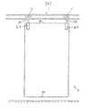
Ein Trennwandelement 1 nach Figur 1, bei dem auf die Darstellung einer
Bodenführung 4 (siehe Figuren 6 bis 9) verzichtet wurde, ist über eine aus
einem Tragprofil 7 gebildete Tragvorrichtung 2 und einem an die Tragvorrichtung
2 angeschlossenen Tragbolzen 20 über eine Rollenführung 5 an
einer Führungsschiene 3 aufgehängt. Eine obere Stirnkante des Trennwandelementes
1 ist mit 11 und eine untere Stirnkante mit 14 bezeichnet.A
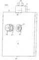
Das Tragprofil 7 der Tragvorrichtung 2 nach Figur 2 besteht im Wesentlichen
aus einem laschenförmigen Profilschenkel 6, der - vorzugsweise einstückig
- mit einem horizontalen Profilschenkel 9 verbunden ist. Der horizontale
Profilschenkel 9 übergreift die obere Stirnkante 11 des in Figur 2
nicht dargestellten Trennwandelementes 1. An den horizontalen Profilschenkel
9 schließt sich ein vertikaler Profilschenkel 10 an, der - wie Figur
4 zeigt - das Trennwandelement 1 seitlich umgreift. Der nach Art eines
Tragkopfes ausgebildete horizontale Profilschenkel 9 besitzt zwei parallel
zueinander verlaufende distanzierte Gewindebohrungen 17, in die Klemmschrauben
18 einfassen. Zwischen den Gewindebohrungen 17 ist eine
größere Bohrung 19 für die Aufnahme des in Figur 1 dargestellten Tragbolzens
20 angeordnet. Die Klemmschrauben 18 wirken auf ein Druckstück
15, welches als Druckplatte 16 ausgebildet ist, und des Weiteren auf
einen, insbesondere bei Glasplatten, vorteilhaften Kantenschutz 21, der in
einer Nut 36 des horizontalen Profilschenkels 9 geführt ist.The
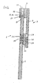
Im in der Bildebene unteren Bereich des laschenförmigen Profilschenkels
6 ist eine schlüssellochartige Bohrung 25 vorgesehen, die dem Anschluss
eines allgemein mit 24 bezeichneten Punkthalters dient. Hierzu weist der
Punkthalter 24 einen Haltebolzen 23 mit einem Bolzenkopf 30 auf, der so
geformt ist, dass er den breiteren Bereich 29 der als vertikales Langloch
27 ausgebildeten Bohrung 25 durchfassen kann und sich, wie Figur 4 erkennen
lässt, versenkt an dem schmaleren Bereich 28 des vertikalen
Langloches 27 abstützen kann. Der Punkthalter 24 besitzt ferner in bekannter
Weise eine Kegelmutter 35, einen kegelförmigen Glasschutz 34
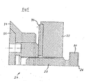
und einen scheibenförmigen Glasschutz 33. Wie Figur 4 erkennen lässt.
ist zwischen dem Trennwandelement 1 und dem laschenförmigen Profilschenkel
6 ein Abstandshalter 22 angeordnet, mit dem die Breite des horizontalen
Profilschenkels 9 der Tragvorrichtung 2 ausgeglichen wird. Eine
Mittellängsachse des Haltebolzens 23 ist mit 26 bezeichnet, so dass der
Haltebolzen 23 fluchtende Bohrungen 25 im Abstandshalter 22, dem Glasschutz
33, dem Glasschutz 34 und der Kegelmutter 35 durchfassen kann,
wie dies insbesondere aus Figur 5 ersichtlich wird.In the lower level of the plate-shaped profile leg in the
Ein Bodenführungsprofil 8 einer Bodenführung 4 nach Figuren 6 bis 9 entspricht
im Wesentlichen dem Tragprofil 7 der Tragvorrichtung 2 mit der
Abweichung, dass zwischen den Gewindebohrungen 17 eine Bohrung 31
angeordnet ist, welche der Aufnahme eines Bodenführungselementes 32
dient. Der horizontale Profilschenkel 12 des Bodenführungsprofiles 8 ist
mit Bezug auf seine Schenkeldicke weniger stark ausgebildet als der horizontale
Profilschenkel 9 der Tragvorrichtung 2, weil auf den horizontalen
Profilschenkel 12 geringere Kräfte einwirken. In vergleichbarer Weise mit
der Tragvorrichtung 2 schließt sich jedoch an den horizontalen Profilschenkel
12 ebenfalls ein vertikaler Profilschenkel 13 an, so dass auch
hier eine nutartige Aufnahme für die untere Stirnkante 14 des Trennwandelementes
1 gebildet wird. A
- 11
- Trennwandelementpartition element
- 22
- Tragvorrichtungcarrying device
- 33
- Führungsschieneguide rail
- 44
- Bodenführungfloor guide
- 55
- Rollenwagenroller carriage
- 66
- laschenförmiger Profilschenkelstrap-shaped profile leg
- 77
- Tragprofilsupport section
- 88th
- BodenführungsprofilFloor guide profile
- 99
- horizontaler Profilschenkel der Tragvorrichtunghorizontal profile leg of the support device
- 1010
- vertikaler Profilschenkel der Tragvorrichtungvertical profile leg of the support device
- 1111
- obere Stirnkanteupper end edge
- 1212
- horizontaler Profilschenkel des Bodenführungsprofileshorizontal profile leg of the floor guide profile
- 1313
- vertikaler Profilschenkel des Bodenführungsprofilesvertical profile leg of the floor guide profile
- 1414
- untere Stirnkantelower front edge
- 1515
- DruckstückPressure piece
- 1616
- Druckplatteprinting plate
- 1717
- Gewindebohrungthreaded hole
- 1818
- Klemmschraubeclamping screw
- 1919
- Bohrungdrilling
- 2020
- Tragbolzensupport bolts
- 2121
- Kantenschutzedge protection
- 2222
- Abstandshalterspacer
- 2323
- Haltebolzenretaining bolt
- 2424
- Punkthalterpoint fixing
- 2525
- Bohrungendrilling
- 2626
- Mittellängsachsecentral longitudinal axis
- 2727
- vertikales Langlochvertical slot
- 2828
- schmalerer Bereichnarrower range
- 2929
- breiterer Bereich wider area
- 3030
- Bolzenkopfbolt head
- 3131
- Bohrungdrilling
- 3232
- BodenführungselementFloor guide element
- 3333
- Glasschutzglass protection
- 3434
- Glasschutzglass protection
- 3535
- Kegelmuttertapered nut
- 3636
- Nutgroove
Claims (9)
- A partition wall component (1), displaceably guided at a guiding rail (3) by means of an upper carrying device (2) and positively guided by means of a lower floor guide (4), the carrying device (2) and the floor guide (4) respectively presenting a plate-shaped profile leg (6) of a carrying profile (7) or of a floor guiding profile (8), which leg extends vertically, is directly or indirectly located at the partition wall component (1), and is screwable with the partition wall component (1), and the carrying device (2) overlaps the upper frontal edge of the partition wall component (1) with a horizontal profile leg (9) and with a vertical profile leg (10) contiguous to the horizontal profile leg (9), and the floor guide (4) overlaps the lower frontal edge (14) of the partition wall component (1) with a horizontal profile leg (12) and with a vertical profile leg (13) contiguous to the horizontal profile leg (12), characterized in that the screwable plate-shaped profile leg (6) is restrictedly displaceable in vertical direction in relation to the partition wall component (1) and the horizontal profile legs (9, 12) of the carrying profile (7) and/or of the floor guide profile (8) overlap the upper and/or lower frontal edge (11, 14) of the partition wall component (1) with play and a pressure pad (15), directly or indirectly adjustable at the frontal edge (11, 14), is disposed between the horizontal profile leg (9, 12) and the frontal edge (11, 14).
- A partition wall component according to claim 1, characterized in that the pressure pad (15) is formed as a pressure plate (16).
- A partition wall component according to claim 1 and 2, characterized in that the horizontal profile leg (9) of the carrying profile (7) and/or the horizontal profile leg (12) of the floor guide profile (8) respectively present at least one threaded borehole (17) for the reception of a clamping screw (18), which is adjustable at the pressure pad (15).
- A partition wall component according to any of the claims 1 to 3, characterized in that the horizontal profile leg (9) of the carrying profile (7) presents two threaded boreholes (17), extending parallel with regard to each other, for the reception of clamping screws (18), and a borehole (19), located between the threaded boreholes (17), for the reception of a carrying bolt (20).
- A partition wall component according to any of the claims 1 to 4, characterized in that an edge protection (21) is disposed between the pressure pad (15) and the upper frontal edge (11) and/or the lower frontal edge (14) of the partition wall component (1 ).
- A partition wall component according to any of the claims 1 to 5, characterized in that a spacer (22) is disposed between the vertically extending plate-shaped profile leg (6) of the carrying device (2) and the partition wall component (1), and in that the partition wall component (1), the spacer (22) and the plate-shaped profile leg (6) present boreholes (25) which are penetrated by the retaining bolt (23) of a single-point fixing (24).
- A partition wall component according to any of the claims 1 to 6, characterized in that the borehole (25) in the plate-shaped profile leg (6) is formed as a vertical oblong hole (27).
- A partition wall component according to claim 7, characterized in that the oblong hole (27) is formed in the shape of a keyhole having a narrower and a wider portion (28, 29), and the retaining bolt (23) of the single-point fixing (24) presents a bolt head (30), such that the latter is able to be inserted through the wider portion (29) and engages at the rear in the part delimiting the narrower portion (28).
- A partition wall component according to any of the claims 1 to 8, characterized in that the horizontal profile leg (12) of the floor guide profile (8) presents two threaded boreholes (17), extending parallel with regard to each other, for the reception of clamping screws (18), and a borehole, (31) located between the threaded boreholes (17), for the reception of a floor guide component (32), which can be positively guided in or at a floor guide.
Applications Claiming Priority (2)
| Application Number | Priority Date | Filing Date | Title |
|---|---|---|---|
| DE10243908A DE10243908B4 (en) | 2002-09-20 | 2002-09-20 | By means of an upper support device on a guide rail and by means of a lower floor guide, a partition element which is guided in a positive manner |
| DE10243908 | 2002-09-20 |
Publications (2)
| Publication Number | Publication Date |
|---|---|
| EP1400647A1 EP1400647A1 (en) | 2004-03-24 |
| EP1400647B1 true EP1400647B1 (en) | 2005-05-18 |
Family
ID=31896265
Family Applications (1)
| Application Number | Title | Priority Date | Filing Date |
|---|---|---|---|
| EP03021257A Expired - Lifetime EP1400647B1 (en) | 2002-09-20 | 2003-09-19 | Partition wall element with a top supporting device and a bottom floor guide |
Country Status (5)
| Country | Link |
|---|---|
| EP (1) | EP1400647B1 (en) |
| AT (1) | ATE295927T1 (en) |
| DE (2) | DE10243908B4 (en) |
| DK (1) | DK1400647T3 (en) |
| ES (1) | ES2239743T3 (en) |
Families Citing this family (2)
| Publication number | Priority date | Publication date | Assignee | Title |
|---|---|---|---|---|
| US10538947B2 (en) | 2016-03-07 | 2020-01-21 | Jeld-Wen, Inc. | Sliding barn door hardware |
| CN111535709A (en) * | 2020-05-21 | 2020-08-14 | 重庆宏亚远桥金属制品有限责任公司 | Energy-saving window structure and construction method thereof |
Family Cites Families (9)
| Publication number | Priority date | Publication date | Assignee | Title |
|---|---|---|---|---|
| CH442067A (en) * | 1965-04-23 | 1967-08-15 | Idealheim Ag | Sliding door |
| US3796405A (en) * | 1972-10-16 | 1974-03-12 | Work Right Prod Inc | Roller bracket |
| FI78962C (en) * | 1987-12-09 | 1989-10-10 | Lemminkaeinen Oy | SVAENGBARA GLAS FOER BALKONG. |
| DE3814535A1 (en) * | 1988-03-29 | 1989-10-19 | Solbach Hans Joachim | Running device for a hanging single-wing or multi-wing sliding wall |
| US4905345A (en) * | 1989-03-09 | 1990-03-06 | Air-Lec Industries, Inc. | Track system for sliding door |
| DE19652773C2 (en) * | 1996-12-19 | 1998-11-26 | Dorma Gmbh & Co Kg | Clamp fitting for fastening glass panes |
| DE29900640U1 (en) * | 1999-01-18 | 1999-04-01 | Dorma Gmbh & Co Kg | Shower partition |
| US6336247B1 (en) * | 2000-05-08 | 2002-01-08 | Frank Schnoor | Screen door hanger assembly |
| DE20203070U1 (en) * | 2002-02-27 | 2003-07-24 | Hueppe Form Raumtrennsysteme G | Support system for movable glass partition in building has rings on bolts engaging large bores on glass and has steadying clamps engaging top edge of glass |
-
2002
- 2002-09-20 DE DE10243908A patent/DE10243908B4/en not_active Expired - Fee Related
-
2003
- 2003-09-19 ES ES03021257T patent/ES2239743T3/en not_active Expired - Lifetime
- 2003-09-19 DK DK03021257T patent/DK1400647T3/en active
- 2003-09-19 AT AT03021257T patent/ATE295927T1/en not_active IP Right Cessation
- 2003-09-19 EP EP03021257A patent/EP1400647B1/en not_active Expired - Lifetime
- 2003-09-19 DE DE50300552T patent/DE50300552D1/en not_active Expired - Lifetime
Also Published As
| Publication number | Publication date |
|---|---|
| ES2239743T3 (en) | 2005-10-01 |
| DE50300552D1 (en) | 2005-06-23 |
| DE10243908B4 (en) | 2004-11-18 |
| DE10243908A1 (en) | 2004-04-15 |
| ATE295927T1 (en) | 2005-06-15 |
| EP1400647A1 (en) | 2004-03-24 |
| DK1400647T3 (en) | 2005-09-19 |
Similar Documents
| Publication | Publication Date | Title |
|---|---|---|
| DE19733367A1 (en) | Door or window panel | |
| DE10212011C1 (en) | Sliding element suspended from a running rail by means of idlers | |
| EP2365167B1 (en) | Hinge, especially for building closing doors | |
| EP3767067A1 (en) | Hinge-sided finger protection device | |
| EP2927409B1 (en) | Sealing arrangement for a push door | |
| EP2365166B1 (en) | Hinge, especially for building closing doors | |
| CH679060A5 (en) | ||
| EP1400647B1 (en) | Partition wall element with a top supporting device and a bottom floor guide | |
| EP0956799B1 (en) | Shower partition | |
| DE10148935A1 (en) | Stop for sliding door in building has support rod attached to door and carrying adjustable guide roller | |
| EP0984126B1 (en) | Guiding device for a sliding door | |
| EP3771793A1 (en) | Fitting for a sliding door | |
| DE10323695B4 (en) | sliding profile | |
| DE4014106C2 (en) | Floor sealing strip for a swing door | |
| DE19835684A1 (en) | Movable door leaf arrangement | |
| DE2339623C3 (en) | Adjustable door hanger | |
| EP0853179B1 (en) | Wing for a door or window or the like | |
| AT3946U1 (en) | SHOWER SEPARATION | |
| EP1025790B1 (en) | Shower partition | |
| EP1443168B1 (en) | Partition wall with a bottom guide | |
| DE10119994B4 (en) | Tool holders | |
| EP3208415A1 (en) | Adjusting device | |
| DE202022101255U1 (en) | Floor/ceiling safety device with locking wall | |
| DE19940132C2 (en) | wrist strap | |
| DE3026599C2 (en) | Holding device for rail-shaped curtain strips |
Legal Events
| Date | Code | Title | Description |
|---|---|---|---|
| PUAI | Public reference made under article 153(3) epc to a published international application that has entered the european phase |
Free format text: ORIGINAL CODE: 0009012 |
|
| AK | Designated contracting states |
Kind code of ref document: A1 Designated state(s): AT BE BG CH CY CZ DE DK EE ES FI FR GB GR HU IE IT LI LU MC NL PT RO SE SI SK TR |
|
| AX | Request for extension of the european patent |
Extension state: AL LT LV MK |
|
| GRAP | Despatch of communication of intention to grant a patent |
Free format text: ORIGINAL CODE: EPIDOSNIGR1 |
|
| 17P | Request for examination filed |
Effective date: 20040924 |
|
| AKX | Designation fees paid |
Designated state(s): AT BE BG CH CY CZ DE DK EE ES FI FR GB GR HU IE IT LI LU MC NL PT RO SE SI SK TR |
|
| GRAS | Grant fee paid |
Free format text: ORIGINAL CODE: EPIDOSNIGR3 |
|
| GRAA | (expected) grant |
Free format text: ORIGINAL CODE: 0009210 |
|
| AK | Designated contracting states |
Kind code of ref document: B1 Designated state(s): AT BE BG CH CY CZ DE DK EE ES FI FR GB GR HU IE IT LI LU MC NL PT RO SE SI SK TR |
|
| PG25 | Lapsed in a contracting state [announced via postgrant information from national office to epo] |
Ref country code: CZ Free format text: LAPSE BECAUSE OF FAILURE TO SUBMIT A TRANSLATION OF THE DESCRIPTION OR TO PAY THE FEE WITHIN THE PRESCRIBED TIME-LIMIT Effective date: 20050518 Ref country code: RO Free format text: LAPSE BECAUSE OF FAILURE TO SUBMIT A TRANSLATION OF THE DESCRIPTION OR TO PAY THE FEE WITHIN THE PRESCRIBED TIME-LIMIT Effective date: 20050518 Ref country code: IE Free format text: LAPSE BECAUSE OF FAILURE TO SUBMIT A TRANSLATION OF THE DESCRIPTION OR TO PAY THE FEE WITHIN THE PRESCRIBED TIME-LIMIT Effective date: 20050518 Ref country code: EE Free format text: LAPSE BECAUSE OF FAILURE TO SUBMIT A TRANSLATION OF THE DESCRIPTION OR TO PAY THE FEE WITHIN THE PRESCRIBED TIME-LIMIT Effective date: 20050518 Ref country code: SI Free format text: LAPSE BECAUSE OF FAILURE TO SUBMIT A TRANSLATION OF THE DESCRIPTION OR TO PAY THE FEE WITHIN THE PRESCRIBED TIME-LIMIT Effective date: 20050518 Ref country code: SK Free format text: LAPSE BECAUSE OF FAILURE TO SUBMIT A TRANSLATION OF THE DESCRIPTION OR TO PAY THE FEE WITHIN THE PRESCRIBED TIME-LIMIT Effective date: 20050518 |
|
| REG | Reference to a national code |
Ref country code: GB Ref legal event code: FG4D Free format text: NOT ENGLISH |
|
| REG | Reference to a national code |
Ref country code: CH Ref legal event code: EP |
|
| REG | Reference to a national code |
Ref country code: CH Ref legal event code: NV Representative=s name: BOVARD AG PATENTANWAELTE Ref country code: IE Ref legal event code: FG4D Free format text: LANGUAGE OF EP DOCUMENT: GERMAN |
|
| REG | Reference to a national code |
Ref country code: SE Ref legal event code: TRGR |
|
| REF | Corresponds to: |
Ref document number: 50300552 Country of ref document: DE Date of ref document: 20050623 Kind code of ref document: P |
|
| PG25 | Lapsed in a contracting state [announced via postgrant information from national office to epo] |
Ref country code: GR Free format text: LAPSE BECAUSE OF FAILURE TO SUBMIT A TRANSLATION OF THE DESCRIPTION OR TO PAY THE FEE WITHIN THE PRESCRIBED TIME-LIMIT Effective date: 20050818 Ref country code: BG Free format text: LAPSE BECAUSE OF FAILURE TO SUBMIT A TRANSLATION OF THE DESCRIPTION OR TO PAY THE FEE WITHIN THE PRESCRIBED TIME-LIMIT Effective date: 20050818 |
|
| PGFP | Annual fee paid to national office [announced via postgrant information from national office to epo] |
Ref country code: TR Payment date: 20050824 Year of fee payment: 5 |
|
| GBT | Gb: translation of ep patent filed (gb section 77(6)(a)/1977) |
Effective date: 20050823 |
|
| PG25 | Lapsed in a contracting state [announced via postgrant information from national office to epo] |
Ref country code: CY Free format text: LAPSE BECAUSE OF FAILURE TO SUBMIT A TRANSLATION OF THE DESCRIPTION OR TO PAY THE FEE WITHIN THE PRESCRIBED TIME-LIMIT Effective date: 20050919 Ref country code: AT Free format text: LAPSE BECAUSE OF NON-PAYMENT OF DUE FEES Effective date: 20050919 |
|
| REG | Reference to a national code |
Ref country code: DK Ref legal event code: T3 |
|
| PG25 | Lapsed in a contracting state [announced via postgrant information from national office to epo] |
Ref country code: MC Free format text: LAPSE BECAUSE OF NON-PAYMENT OF DUE FEES Effective date: 20050930 Ref country code: LU Free format text: LAPSE BECAUSE OF NON-PAYMENT OF DUE FEES Effective date: 20050930 |
|
| REG | Reference to a national code |
Ref country code: ES Ref legal event code: FG2A Ref document number: 2239743 Country of ref document: ES Kind code of ref document: T3 |
|
| PG25 | Lapsed in a contracting state [announced via postgrant information from national office to epo] |
Ref country code: PT Free format text: LAPSE BECAUSE OF FAILURE TO SUBMIT A TRANSLATION OF THE DESCRIPTION OR TO PAY THE FEE WITHIN THE PRESCRIBED TIME-LIMIT Effective date: 20051024 |
|
| PG25 | Lapsed in a contracting state [announced via postgrant information from national office to epo] |
Ref country code: HU Free format text: LAPSE BECAUSE OF FAILURE TO SUBMIT A TRANSLATION OF THE DESCRIPTION OR TO PAY THE FEE WITHIN THE PRESCRIBED TIME-LIMIT Effective date: 20051119 |
|
| REG | Reference to a national code |
Ref country code: IE Ref legal event code: FD4D |
|
| PLBE | No opposition filed within time limit |
Free format text: ORIGINAL CODE: 0009261 |
|
| STAA | Information on the status of an ep patent application or granted ep patent |
Free format text: STATUS: NO OPPOSITION FILED WITHIN TIME LIMIT |
|
| ET | Fr: translation filed | ||
| 26N | No opposition filed |
Effective date: 20060221 |
|
| PGFP | Annual fee paid to national office [announced via postgrant information from national office to epo] |
Ref country code: DK Payment date: 20070914 Year of fee payment: 5 |
|
| PGFP | Annual fee paid to national office [announced via postgrant information from national office to epo] |
Ref country code: ES Payment date: 20070927 Year of fee payment: 5 |
|
| PGFP | Annual fee paid to national office [announced via postgrant information from national office to epo] |
Ref country code: FI Payment date: 20070913 Year of fee payment: 5 |
|
| PGFP | Annual fee paid to national office [announced via postgrant information from national office to epo] |
Ref country code: GB Payment date: 20070914 Year of fee payment: 5 |
|
| PGFP | Annual fee paid to national office [announced via postgrant information from national office to epo] |
Ref country code: IT Payment date: 20070922 Year of fee payment: 5 Ref country code: SE Payment date: 20060914 Year of fee payment: 4 |
|
| PG25 | Lapsed in a contracting state [announced via postgrant information from national office to epo] |
Ref country code: SE Free format text: LAPSE BECAUSE OF NON-PAYMENT OF DUE FEES Effective date: 20070920 |
|
| EUG | Se: european patent has lapsed | ||
| REG | Reference to a national code |
Ref country code: DK Ref legal event code: EBP |
|
| GBPC | Gb: european patent ceased through non-payment of renewal fee |
Effective date: 20080919 |
|
| PG25 | Lapsed in a contracting state [announced via postgrant information from national office to epo] |
Ref country code: FI Free format text: LAPSE BECAUSE OF NON-PAYMENT OF DUE FEES Effective date: 20080919 |
|
| PG25 | Lapsed in a contracting state [announced via postgrant information from national office to epo] |
Ref country code: IT Free format text: LAPSE BECAUSE OF NON-PAYMENT OF DUE FEES Effective date: 20080919 |
|
| REG | Reference to a national code |
Ref country code: ES Ref legal event code: FD2A Effective date: 20080920 |
|
| PG25 | Lapsed in a contracting state [announced via postgrant information from national office to epo] |
Ref country code: GB Free format text: LAPSE BECAUSE OF NON-PAYMENT OF DUE FEES Effective date: 20080919 |
|
| PG25 | Lapsed in a contracting state [announced via postgrant information from national office to epo] |
Ref country code: ES Free format text: LAPSE BECAUSE OF NON-PAYMENT OF DUE FEES Effective date: 20080920 |
|
| PG25 | Lapsed in a contracting state [announced via postgrant information from national office to epo] |
Ref country code: DK Free format text: LAPSE BECAUSE OF NON-PAYMENT OF DUE FEES Effective date: 20090331 |
|
| REG | Reference to a national code |
Ref country code: CH Ref legal event code: PCOW Free format text: DORMA GMBH + CO. KG;DORMA PLATZ 1;58256 ENNEPETAL (DE) |
|
| PGFP | Annual fee paid to national office [announced via postgrant information from national office to epo] |
Ref country code: CH Payment date: 20100923 Year of fee payment: 8 |
|
| PGFP | Annual fee paid to national office [announced via postgrant information from national office to epo] |
Ref country code: FR Payment date: 20101005 Year of fee payment: 8 |
|
| PGFP | Annual fee paid to national office [announced via postgrant information from national office to epo] |
Ref country code: NL Payment date: 20100916 Year of fee payment: 8 |
|
| PGFP | Annual fee paid to national office [announced via postgrant information from national office to epo] |
Ref country code: BE Payment date: 20100913 Year of fee payment: 8 |
|
| REG | Reference to a national code |
Ref country code: CH Ref legal event code: PFA Owner name: DORMA GMBH + CO. KG Free format text: DORMA GMBH + CO. KG#DORMA PLATZ 1#58256 ENNEPETAL (DE) -TRANSFER TO- DORMA GMBH + CO. KG#DORMA PLATZ 1#58256 ENNEPETAL (DE) |
|
| PG25 | Lapsed in a contracting state [announced via postgrant information from national office to epo] |
Ref country code: TR Free format text: LAPSE BECAUSE OF NON-PAYMENT OF DUE FEES Effective date: 20100917 |
|
| BERE | Be: lapsed |
Owner name: *DORMA G.M.B.H. + CO. K.G. Effective date: 20110930 |
|
| REG | Reference to a national code |
Ref country code: NL Ref legal event code: V1 Effective date: 20120401 |
|
| REG | Reference to a national code |
Ref country code: CH Ref legal event code: PL |
|
| REG | Reference to a national code |
Ref country code: FR Ref legal event code: ST Effective date: 20120531 |
|
| PG25 | Lapsed in a contracting state [announced via postgrant information from national office to epo] |
Ref country code: BE Free format text: LAPSE BECAUSE OF NON-PAYMENT OF DUE FEES Effective date: 20110930 |
|
| PG25 | Lapsed in a contracting state [announced via postgrant information from national office to epo] |
Ref country code: LI Free format text: LAPSE BECAUSE OF NON-PAYMENT OF DUE FEES Effective date: 20110930 Ref country code: CH Free format text: LAPSE BECAUSE OF NON-PAYMENT OF DUE FEES Effective date: 20110930 Ref country code: NL Free format text: LAPSE BECAUSE OF NON-PAYMENT OF DUE FEES Effective date: 20120401 |
|
| PG25 | Lapsed in a contracting state [announced via postgrant information from national office to epo] |
Ref country code: FR Free format text: LAPSE BECAUSE OF NON-PAYMENT OF DUE FEES Effective date: 20110930 |
|
| PG25 | Lapsed in a contracting state [announced via postgrant information from national office to epo] |
Ref country code: TR Free format text: LAPSE BECAUSE OF NON-PAYMENT OF DUE FEES Effective date: 20080919 |
|
| REG | Reference to a national code |
Ref country code: DE Ref legal event code: R081 Ref document number: 50300552 Country of ref document: DE Owner name: DORMA DEUTSCHLAND GMBH, DE Free format text: FORMER OWNER: DORMA GMBH + CO. KG, 58256 ENNEPETAL, DE Effective date: 20141205 |
|
| REG | Reference to a national code |
Ref country code: DE Ref legal event code: R082 Ref document number: 50300552 Country of ref document: DE Representative=s name: BALDER IP LAW, S.L., ES |
|
| PGFP | Annual fee paid to national office [announced via postgrant information from national office to epo] |
Ref country code: DE Payment date: 20150922 Year of fee payment: 13 |
|
| REG | Reference to a national code |
Ref country code: DE Ref legal event code: R119 Ref document number: 50300552 Country of ref document: DE |
|
| PG25 | Lapsed in a contracting state [announced via postgrant information from national office to epo] |
Ref country code: DE Free format text: LAPSE BECAUSE OF NON-PAYMENT OF DUE FEES Effective date: 20170401 |