EP1400359A2 - Koaleszenzfrei Tintenstrahldrucken durch kontrollierte Tropfverteilung auf/in dem Empfangselement - Google Patents
Koaleszenzfrei Tintenstrahldrucken durch kontrollierte Tropfverteilung auf/in dem Empfangselement Download PDFInfo
- Publication number
- EP1400359A2 EP1400359A2 EP03077855A EP03077855A EP1400359A2 EP 1400359 A2 EP1400359 A2 EP 1400359A2 EP 03077855 A EP03077855 A EP 03077855A EP 03077855 A EP03077855 A EP 03077855A EP 1400359 A2 EP1400359 A2 EP 1400359A2
- Authority
- EP
- European Patent Office
- Prior art keywords
- drop
- medium
- receiver medium
- drops
- receiver
- Prior art date
- Legal status (The legal status is an assumption and is not a legal conclusion. Google has not performed a legal analysis and makes no representation as to the accuracy of the status listed.)
- Withdrawn
Links
- 238000003892 spreading Methods 0.000 title claims abstract description 40
- 230000007480 spreading Effects 0.000 title claims abstract description 40
- 238000007641 inkjet printing Methods 0.000 title claims description 16
- 238000007639 printing Methods 0.000 claims abstract description 67
- 239000007788 liquid Substances 0.000 claims abstract description 40
- 238000000034 method Methods 0.000 claims abstract description 33
- 238000000151 deposition Methods 0.000 claims abstract description 9
- 230000004044 response Effects 0.000 claims description 6
- 239000000976 ink Substances 0.000 description 79
- 239000011148 porous material Substances 0.000 description 15
- 238000000576 coating method Methods 0.000 description 12
- 239000011248 coating agent Substances 0.000 description 10
- 239000011800 void material Substances 0.000 description 10
- 239000004372 Polyvinyl alcohol Substances 0.000 description 9
- 229920002451 polyvinyl alcohol Polymers 0.000 description 9
- VYPSYNLAJGMNEJ-UHFFFAOYSA-N Silicium dioxide Chemical compound O=[Si]=O VYPSYNLAJGMNEJ-UHFFFAOYSA-N 0.000 description 8
- 238000009736 wetting Methods 0.000 description 7
- PNEYBMLMFCGWSK-UHFFFAOYSA-N aluminium oxide Inorganic materials [O-2].[O-2].[O-2].[Al+3].[Al+3] PNEYBMLMFCGWSK-UHFFFAOYSA-N 0.000 description 6
- 238000004581 coalescence Methods 0.000 description 6
- 230000005684 electric field Effects 0.000 description 5
- 238000009792 diffusion process Methods 0.000 description 4
- 230000006870 function Effects 0.000 description 4
- 239000000049 pigment Substances 0.000 description 4
- 239000000377 silicon dioxide Substances 0.000 description 4
- 238000001179 sorption measurement Methods 0.000 description 4
- 238000012546 transfer Methods 0.000 description 4
- 230000000694 effects Effects 0.000 description 3
- 238000005516 engineering process Methods 0.000 description 3
- 239000012530 fluid Substances 0.000 description 3
- 239000000463 material Substances 0.000 description 3
- QSHDDOUJBYECFT-UHFFFAOYSA-N mercury Chemical compound [Hg] QSHDDOUJBYECFT-UHFFFAOYSA-N 0.000 description 3
- 229910052753 mercury Inorganic materials 0.000 description 3
- 239000000203 mixture Substances 0.000 description 3
- 230000000704 physical effect Effects 0.000 description 3
- 230000008569 process Effects 0.000 description 3
- 239000007787 solid Substances 0.000 description 3
- 239000000758 substrate Substances 0.000 description 3
- FCTDKZOUZXYHNA-UHFFFAOYSA-N 1,4-dioxane-2,2-diol Chemical compound OC1(O)COCCO1 FCTDKZOUZXYHNA-UHFFFAOYSA-N 0.000 description 2
- XUIMIQQOPSSXEZ-UHFFFAOYSA-N Silicon Chemical compound [Si] XUIMIQQOPSSXEZ-UHFFFAOYSA-N 0.000 description 2
- 239000011230 binding agent Substances 0.000 description 2
- 230000008859 change Effects 0.000 description 2
- 239000003086 colorant Substances 0.000 description 2
- 239000013078 crystal Substances 0.000 description 2
- 230000007423 decrease Effects 0.000 description 2
- 230000003247 decreasing effect Effects 0.000 description 2
- 238000011161 development Methods 0.000 description 2
- 238000003384 imaging method Methods 0.000 description 2
- 229910010272 inorganic material Inorganic materials 0.000 description 2
- 239000011147 inorganic material Substances 0.000 description 2
- 239000010954 inorganic particle Substances 0.000 description 2
- 239000011368 organic material Substances 0.000 description 2
- 239000002245 particle Substances 0.000 description 2
- 229910052710 silicon Inorganic materials 0.000 description 2
- 239000010703 silicon Substances 0.000 description 2
- 239000002904 solvent Substances 0.000 description 2
- 206010037867 Rash macular Diseases 0.000 description 1
- 230000009471 action Effects 0.000 description 1
- 239000000654 additive Substances 0.000 description 1
- 230000000996 additive effect Effects 0.000 description 1
- 230000006399 behavior Effects 0.000 description 1
- 230000015572 biosynthetic process Effects 0.000 description 1
- 238000004364 calculation method Methods 0.000 description 1
- 239000004020 conductor Substances 0.000 description 1
- 230000007547 defect Effects 0.000 description 1
- 238000009826 distribution Methods 0.000 description 1
- 238000001035 drying Methods 0.000 description 1
- 239000001041 dye based ink Substances 0.000 description 1
- 230000008030 elimination Effects 0.000 description 1
- 238000003379 elimination reaction Methods 0.000 description 1
- 238000010304 firing Methods 0.000 description 1
- 239000011521 glass Substances 0.000 description 1
- 238000010438 heat treatment Methods 0.000 description 1
- 238000005213 imbibition Methods 0.000 description 1
- 230000003116 impacting effect Effects 0.000 description 1
- 238000012886 linear function Methods 0.000 description 1
- 238000005259 measurement Methods 0.000 description 1
- 230000007246 mechanism Effects 0.000 description 1
- 239000005022 packaging material Substances 0.000 description 1
- 238000004806 packaging method and process Methods 0.000 description 1
- 230000035515 penetration Effects 0.000 description 1
- 229920003023 plastic Polymers 0.000 description 1
- 239000004033 plastic Substances 0.000 description 1
- 239000004848 polyfunctional curative Substances 0.000 description 1
- 229920005862 polyol Polymers 0.000 description 1
- 150000003077 polyols Chemical class 0.000 description 1
- 238000002459 porosimetry Methods 0.000 description 1
- 238000003825 pressing Methods 0.000 description 1
- 238000012545 processing Methods 0.000 description 1
- 230000001681 protective effect Effects 0.000 description 1
- 230000001846 repelling effect Effects 0.000 description 1
- 231100000817 safety factor Toxicity 0.000 description 1
- 229920006395 saturated elastomer Polymers 0.000 description 1
- 230000001360 synchronised effect Effects 0.000 description 1
- XLYOFNOQVPJJNP-UHFFFAOYSA-N water Substances O XLYOFNOQVPJJNP-UHFFFAOYSA-N 0.000 description 1
- 238000005303 weighing Methods 0.000 description 1
Images


Classifications
-
- B—PERFORMING OPERATIONS; TRANSPORTING
- B41—PRINTING; LINING MACHINES; TYPEWRITERS; STAMPS
- B41M—PRINTING, DUPLICATING, MARKING, OR COPYING PROCESSES; COLOUR PRINTING
- B41M5/00—Duplicating or marking methods; Sheet materials for use therein
-
- B—PERFORMING OPERATIONS; TRANSPORTING
- B41—PRINTING; LINING MACHINES; TYPEWRITERS; STAMPS
- B41J—TYPEWRITERS; SELECTIVE PRINTING MECHANISMS, i.e. MECHANISMS PRINTING OTHERWISE THAN FROM A FORME; CORRECTION OF TYPOGRAPHICAL ERRORS
- B41J11/00—Devices or arrangements of selective printing mechanisms, e.g. ink-jet printers or thermal printers, for supporting or handling copy material in sheet or web form
- B41J11/009—Detecting type of paper, e.g. by automatic reading of a code that is printed on a paper package or on a paper roll or by sensing the grade of translucency of the paper
-
- B—PERFORMING OPERATIONS; TRANSPORTING
- B41—PRINTING; LINING MACHINES; TYPEWRITERS; STAMPS
- B41J—TYPEWRITERS; SELECTIVE PRINTING MECHANISMS, i.e. MECHANISMS PRINTING OTHERWISE THAN FROM A FORME; CORRECTION OF TYPOGRAPHICAL ERRORS
- B41J13/00—Devices or arrangements of selective printing mechanisms, e.g. ink-jet printers or thermal printers, specially adapted for supporting or handling copy material in short lengths, e.g. sheets
- B41J13/0081—Sheet-storing packages, e.g. for protecting the sheets against ambient influences, e.g. light, humidity, changes in temperature
-
- B—PERFORMING OPERATIONS; TRANSPORTING
- B41—PRINTING; LINING MACHINES; TYPEWRITERS; STAMPS
- B41J—TYPEWRITERS; SELECTIVE PRINTING MECHANISMS, i.e. MECHANISMS PRINTING OTHERWISE THAN FROM A FORME; CORRECTION OF TYPOGRAPHICAL ERRORS
- B41J2/00—Typewriters or selective printing mechanisms characterised by the printing or marking process for which they are designed
- B41J2/005—Typewriters or selective printing mechanisms characterised by the printing or marking process for which they are designed characterised by bringing liquid or particles selectively into contact with a printing material
- B41J2/01—Ink jet
- B41J2/21—Ink jet for multi-colour printing
- B41J2/2121—Ink jet for multi-colour printing characterised by dot size, e.g. combinations of printed dots of different diameter
Definitions
- This invention relates to inkjet printing systems and printing methods and to receivers for use therewith.
- Inkjet printing has become recognized as a prominent contender in the digitally controlled, electronic printing arena because, e.g., of its non-impact, low noise characteristics and system simplicity. For these reasons, inkjet printers have achieved commercial success for home and office use and other areas. Inkjet printing mechanisms can be categorized as either continuous (CIJ) or Drop-on-Demand (DOD).
- CIJ continuous
- DOD Drop-on-Demand
- Piezoelectric DOD printers have achieved commercial success at image resolutions greater than 720 dpi for home and office printers.
- Great Britain Patent No. 2,007, 162 which issued to Endo et al., in 1979, discloses an electrothermal drop-on-demand ink jet printer that applies a power pulse to a heater which is in thermal contact with water based ink in an ink channel. A small quantity of ink rapidly evaporates, forming a bubble, which causes a drop of ink to be ejected from small apertures along an edge of an ink channel.
- This technology is known as thermal ink jet or bubble jet.
- Thermal ink jet printing typically requires that the heater generates an energy impulse enough to heat the ink to a temperature near 400°C which causes a rapid formation of a bubble.
- U.S. Patent No. 4,346, 387 entitled METHOD AND APPARATUS FOR CONTROLLING THE ELECTRIC CHARGE ON DROPLETS AND INK JET RECORDER INCORPORATING THE SAME, issued in the name of Carl H. Hertz on August 24, 1982, discloses a CIJ system. Such a system requires that the droplets produced be charged and then deflected into a gutter or onto the printing medium.
- 5,739,831 entitled ELECTRIC FIELD DRIVEN INK JET PRINTER HAVING A RESILIENT PLATE DEFORMED BY AN ELECTROSTATIC ATTRACTION FORCE BETWEEN SPACED APART ELECTRODES, issued to Haruo Nakamura on April 14,1998, discloses an electric field drive type printhead that applies an external laser light through a transparent glass substrate. The laser light strikes a photo conductive material causing it to become conductive thus completing the electrical path for the electrical field. Completion of the electrical path causes the electrical field to collapse around individual segments. These segments are in a deformed state due to their electro-mechanical response to the applied electric field.
- coalescence or puddling which is observed when wet ink drops touch one another on the receiver surface.
- This coalescence artifact which often occurs in high-speed printing, causes images to appear blotchy or "puddled", resulting in nonuniformity in solid fill areas.
- overhead transfer film may have an image recorded thereon wherein the drops are allowed to spread by a factor of 3.5X until optimal overlap of adjacent dots is achieved.
- the maximum drop diameters shortly after the impact must be less than the pixel spacing.
- Adamic and Gibney disclose the use of an additive (e.g., ployether polyol) in the ink to reduce the surface tension of the ink and increase the drop mass per firing. Reduced surface tension increases the wettability of ink on paper and thus enables faster ink penetration into the paper. This would alleviate the coalescence problem. However, decreasing the surface tension of ink would affect the jettability of the printhead, particularly for a piezo printhead. Furthermore, it would increase the dot size and thus reduce the print quality.
- an additive e.g., ployether polyol
- Lin et al. U. S. Pat. No. 4,748,453 disclose a method of depositing spots of liquid ink upon selected pixel centers in a checkerboard pattern on overhead transparencies so as to prevent the flow of ink from one spot to an overlapping adjacent spot. This method uses at least two passes to complete the deposit of ink on all the pixels in a desired area.
- N-pass printing N> 1 or multipass printing, would reduce the printer productivity by a factor of N.
- single pass printing refers to printing wherein ink drops are permitted to be deposited simultaneously or substantially simultaneously at adjacent pixel locations during relative movement between the printhead and the receiver medium. This is distinguished from non-single pass printing wherein predetermined patterns are established to insure that adjacent pixel locations do not have ink drops deposited simultaneously or substantially simultaneously to prevent coalescence of the drops.
- a second, third or fourth pass is initiated to fill in ink drops at particular locations that were skipped during the first pass.
- the invention is directed to systems and methods that operate in a single pass printing mode and that such may be a mode of operation for high-speed operation of a particular printing apparatus which may also have the capability to operate in a multipass printing mode.
- the spreading of an ink drop into a receiver consists of two different physical processes: (1) the splaying of ink drop because of the impact effect, and (2) the mass transfer of ink drop into the receiver because of capillary action (for porous media) or molecular diffusion (for non-porous media).
- the impact process happens in a relatively short time ( ⁇ 10 to 100 ⁇ sec) and provides the starting condition for the mass transfer process.
- the total spreading for an ink drop impinging on a receiver consists of two components, namely, the spreading due to the impact effect, and the spreading due to the mass transport phenomenon within the receiver.
- Figure 1 is a schematic of drop spreading on the receiver surface and inside the receiver.
- the impact spread factor S i which is defined by the ratio of D i to d , depends only on the Weber number ( We ) and the Reynolds number (Re) of the drop, independently of receiver characteristics.
- An empirical formula correlating D i , We , and Re was given by Asai et al. in "Impact of an Ink Drop on Paper, " IS&T 7 th International Congress on Advances in Non-Impact Printing Technologies, Vol. II, p. 146, (1991).
- a , b , and c are constants
- ⁇ is the drop velocity
- ⁇ , ⁇ , and ⁇ are the density, surface tension, and viscosity of the ink, respectively.
- the impact spread factor increases with increasing drop diameter and drop velocity but decreases with increasing surface tension and viscosity of the ink.
- the impact spread factor can be controlled by varying the drop diameter and drop velocity. Based on experimental results, range of S i is between 1.26 and 4.0.
- Figure 2 shows the dependence of impact spread factor on the Weber number.
- the values of a, b , and c used in the Asai model to fit the measured data by Chaidron et al., "Study of the Impact of Drops on Solid Surfaces," IS&T 15 th International Congress on Advances in Non-Impact Printing Technologies," p.70, (1999) are 1.48, 0.22, and 0.29, respectively. It is noted that the model results are in very good agreement with the experimental data.
- the media spread factor depends primarily on the physical properties of the media such as the porosity (for a porous medium) and the diffusion constant (for a non-porous medium).
- the effect of porosity on drop spreading in a porous medium has been studied by the inventors in detail using the sharp interface model.
- the interface between a region of the medium that is fully saturated with liquid and a region of the medium that is fully unsaturated is considered infinitely sharp.
- the capillary pressure that draws the fluid into the medium is considered constant and independent of the saturation level of the medium.
- the inventors calculated the maximal radial spread of the liquid as a function of the medium porosity.
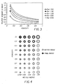
- Figure 3 shows the relative increase in radius due to the adsorption in the medium ( ⁇ m ) as a function of porosity for different values of the wetted radius, R w (i.e., the drop radius after impact).
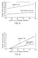
- Figures 5 and 6 show the dependence of porosity and void volume on mass fraction of inorganic material for the silica/PVA and fumed alumina/PVA coatings, respectively.
- Figure 8 is a table showing respective drop sizes, drop spreading, and receiver examples for coalescence-free printing.
- the printing resolution is 600 dpi
- the safety factors ⁇ and ⁇ are chosen to be 0.9 and 1.0, respectively, and the impact spread factor ( S i ) is 1.48.
- the required drop volume, porosity, and weight percentage of fumed alumina in the binary porous coating (fumed alumina/PVA) are 8.9 pL, 0.26, and 46.2%, respectively, for achieving coalescence-free printing.
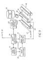
- an inkjet printer system includes an image source 10 such as a scanner or computer which provides raster image data, outlined image data in the form of page description language, or other forms of digital image data.
- This image data is converted to halftoned or other bitmapped image data by an image processing unit 12 which also stores the image data in a memory.
- a plurality of control circuits 14, well known in the art, are provided and which respond to data from the image memory and apply time-varying electrical pulses to circuitry on the printhead 16 associated with each of the nozzles that are also located on the printhead.
- the printhead may be comprised of piezoelectric actuated ink ejecting nozzles, thermal actuated ink ejecting nozzles both in a drop-on-demand inkjet printer.
- the inkjet printhead may be one known as a continuous inkjet printhead wherein droplets are created some of which are selectively directed toward the receiver medium and others are selectively trapped without contacting the receiver medium in accordance with image information to be printed.
- the control system may be one which is adapted to provide varying drop sizes depending upon the requirements of the image data to be printed.
- the image data for each pixel to be printed may be represented by more than one bit of image data to allow for many different drop sizes, preferably forming dots Di up to less than 1/R in size for the maximum size dot in the single pass mode of printing and prior to spread due to porosity of the medium.
- an image data signal of four bits per pixel bit depth may define up to 16 different drop sizes and thus pixel sizes of from 0 to 15 relative sizes.
- Variations in dot size at a pixel location may also be provided by depositing multiple drops in quick succession at the pixel location during a single pass to form a dot on the receiver surface having a dot size Di up to less than 1/R in size prior to spread due to porosity of the medium.
- the image data may be represented by only one bit per pixel bit depth; i.e. either a drop is deposited or not at a pixel location and all drops deposited are substantially the same size.
- Inkjet control circuits are known for creating these different drop sizes in accordance with the image information to be printed. The pulses are applied at an appropriate time, and to the appropriate nozzle, so that the drops formed will form dots on a recording medium 18 in the appropriate position designated by the data in the image memory.
- the receiver medium 18 is moved relative to printhead 16 by recording medium transport system 20, which is electronically controlled by a receiver medium transport control system 22 and which in turn is controlled by micro-controller 24.
- the receiver medium transport system may take many different mechanical configurations. In the case of page wide printheads, it is most convenient to move receiver medium 18 past a stationary printhead 16. However, in the case of scanning print systems, it is usually more convenient to move the printhead along one axis (the sub-scanning direction) and the recording medium along an orthogonal axis (the main scanning direction) in a relative raster motion.
- the printhead may be a 2D printhead such as a full page size printhead for printing plural lines of images including a full page simultaneously or substantially simultaneously.
- the printhead 16 may comprise three or more rows of nozzles, each row being of a pagewidth in dimension and each printing with a different color ink with the rows of nozzles operating substantially simultaneously.
- Each of the rows of nozzles comprises a series of nozzles spaced from each other uniformly at a spacing of 1/R.
- the rows of nozzles may be spaced from adjacent rows also by a spacing of 1/R.
- printing is through single pass printing wherein all of the colors for the image to be printed are printed through a single pass of the printhead relative to the receiver medium.
- Ink is contained in an ink reservoir 28 which may be under pressure in some printing systems.
- the ink is distributed to the back surface of printhead 16 by an ink channel device 30.
- the ink preferably flows through slots and/or holes etched through a silicon substrate of printhead 16 to its front surface, where a plurality of nozzles are situated.
- micro-controller 24 is responsive to an input signal related to the media spread factor Sm for the receiver sheet being printed upon.
- a sensor 27 detects indicia on a backside of the receiver sheet that provides information relative to the spread factor Sm of the receiver sheet.
- indicia 31 may comprise a barcode or other type of printed or coated indicia and the sensor 27 may be located proximate the backside of the receiver sheet for detecting the indicia as the receiver sheet 18 enters the printing station.
- the indicia 32 may be provided on the packaging 33 of the receiver sheets, see Figure.
- the microcontroller 24 includes memory that stores tables for associating receiver media spread factor Sm with drop size or sizes appropriate for the printing on the particular medium in accordance with the invention. These tables may have stored therein different values of drop sizes in accordance with the resolution, R, of the image to be printed.
- the inks and receiver media used with the invention are preferably those that provide for adsorption and spreading of the ink through a porous material wherein the spreading is through a pressure gradient and spreading substantially terminates relatively quickly even though there remains a concentration gradient of the colorant.
- the porous material is typically 20-40 micrometers in thickness and may or may not be coated on a substrate and may or may not contain a mordant.
- the thickness of the porous layer is made sufficiently thick to hold the volume of ink to be deposited therein.
- the concentration of dye or pigment within the carrier fluid of a drop is typically between about one percent and three percent.
- the support for supporting these layers may comprise paper or plastic transparency material.
- the receiver may also be made up of multiple layers of porous materials. As it is known to print printing plates using an inkjet printhead that deposits ink attracting or ink repelling dots, the invention also contemplates depositing such liquids on printing plates that are eventually used to selectively attract ink thereto for printing on receiver sheets.
- Receiver media having a gelatinous overcoat are not suited for the invention as diffusion continues and typically is terminated by drying of the solvent carrier such as by placing the printed receiver media in a sleeve as noted in the prior art cited above.
- placing of the printed receiver media in a blotting means such as a sleeve is not required.
- the invention preferably employs a receiver medium with a porous coated layer so that ink transport tends to be two to three orders of magnitude faster than in a nonporous media due to capillary forces being such that there is fast transport of the ink.
- the media with a porous coated layer has a structure that includes inorganic particles (such as fumed alumina and silica) in an organic binder (such as polyvinyl alcohol (PVA)) with a hardener (such as dihydroxydioxane (DHD)), that comprises the porous coated layer upon which the ink drops are deposited.
- inorganic particles such as fumed alumina and silica
- organic binder such as polyvinyl alcohol (PVA)
- PVA polyvinyl alcohol
- DHD dihydroxydioxane
- the media drop spread factor is preferably in the range of 2 1/2 ⁇ Sm ⁇ 2x2 1/2 , wherein 2 1/2 is the square root of 2 or 1.414, and more preferably in the range of 1.414 ⁇ Sm ⁇ 2.357. A most preferred range is 1.414 ⁇ Sm ⁇ 1.768.
- Preferred printing resolutions are in the range of 150 DPI-6000 DPI, more preferably 300 DPI-2400 DPI, and most preferably 600 DPI-1200 DPI.
- Preferred drop impact dot sizes are preferably in the range 0.5/R ⁇ Di ⁇ 1/R, more preferably 0.7/R ⁇ Di ⁇ 0.9/R, and most preferably 0.8/R ⁇ Di ⁇ 0.9/R.
- Preferred ranges of final dot sizes are 2 1/2 /R ⁇ D ⁇ 2.0/R, more preferably 1.5/R ⁇ D ⁇ 1.8/R, and most preferably 1.1x 2 1/2 /R ⁇ D ⁇ 1.7/R.
- Porosity of the layer in which the ink dots spread is preferably in the range of 0.2-0.8, more preferably in the range of 0.25-0.7, and most preferably in the range of 0.3-0.5. Porosity is determined by the ratio of the volume of the void in the layer to the total volume of the layer. The volume of the void is the interstices between the inorganic particles bound by the binder. This is a well-known definition of porosity.
- ink drops were ejected periodically by a piezoelectric inkjet printhead so as to impinge perpendicularly upon a receiver medium.
- the size and the velocity of ink drops were controlled by the electric pulse applied to the printhead.
- the apparatus used to observe the behavior of ink drops includes a microscope, a CCD camera, a strobe light synchronized to the drive pulse, imaging optics, a translating stage for receiver medium transport, a monitor, and image acquisition hardware and software, to support both still and video rate image capture. Different stages of the spreading phenomenon were observed by changing the delay of lighting.
- the size of an ink drop right after the impact (Di) with the receiver medium is measured and calibrated against a known length.
- the size (d) of an ink drop before impacting the medium can be determined by weighing the added weight to a container to which a large known number of ink drops (in the millions) are fired from a print head.
- the ink drop is assumed to be a sphere when in free flight between the printhead and the receiver medium and has a known density.
- the drop size (d) can then be calculated.
- the final dot size (D) can be measured with a microscope by ejecting isolated single drops on the medium. References describing procedures for measuring dot size include:
- Porosity is referred as the "openness" of a material - the size and number of air-containing spaces within a material. Specifically, porosity is defined as the ratio of the volume of open pores to the total volume of the solid. In general, the porosity of a porous material can be measured accurately by the "Mercury Intrusion Method". Details of the method can be found in "Adsorption, Surface Area and Porosity," Second Edition, p. 173-190, by S. J. Gregg and K. S. W. Sing, Academic Press, London, 1982. The principle of measurement is as follows:
- a non-wetting liquid like mercury does not fill pores in a sample spontaneously because the sample/non-wetting liquid surface free energy is greater than the sample/gas surface free energy.
- application of pressure can force a non-wetting liquid into the pores of a sample.
- a typical porosimeter is made by Porous Materials, Inc., 83 Brown Road, Ithaca, NY 14850, Model No. AMP-200-A-1.
- the inks referred to herein may be dye based inks and inks with pigments particularly where the pigments have particle sizes smaller than half the pore size of the receiver's top layer (preferably smaller than one tenth the pore size of the receiver' top layer) so the pigment particles can transport through the receiver's top layer and spread.
- the surface tension and viscosity of the inks or printing liquids employed are typically related to the type of printhead; i.e. thermal, piezo electric, continuous, with variations within these categories of printhead types.
- these inks or printing liquids have a viscosity in the range of: 1 to 8 cP and a surface tension tension in the range of: 10 to 50 dyne/cm.
- Ink or printing liquid volume drop ranges may be from 0.1 pL to 128 pL. Consistent with the discussion of gray level printing described herein, ultimate drop size at a pixel location can be produced by depositing multiple drops at the pixel location.
- the image receiving layer in which the drops spread may have a thickness of between 20 and 150 microns for the porosity range of 0.2 to 0.8.
Landscapes
- Ink Jet (AREA)
- Ink Jet Recording Methods And Recording Media Thereof (AREA)
Applications Claiming Priority (2)
| Application Number | Priority Date | Filing Date | Title |
|---|---|---|---|
| US252312 | 1981-04-09 | ||
| US10/252,312 US6702425B1 (en) | 2002-09-23 | 2002-09-23 | Coalescence-free inkjet printing by controlling drop spreading on/in a receiver |
Publications (2)
| Publication Number | Publication Date |
|---|---|
| EP1400359A2 true EP1400359A2 (de) | 2004-03-24 |
| EP1400359A3 EP1400359A3 (de) | 2004-12-15 |
Family
ID=31887852
Family Applications (1)
| Application Number | Title | Priority Date | Filing Date |
|---|---|---|---|
| EP03077855A Withdrawn EP1400359A3 (de) | 2002-09-23 | 2003-09-11 | Koaleszenzfrei Tintenstrahldrucken durch kontrollierte Tropfverteilung auf/in dem Empfangselement |
Country Status (3)
| Country | Link |
|---|---|
| US (1) | US6702425B1 (de) |
| EP (1) | EP1400359A3 (de) |
| JP (1) | JP2004114688A (de) |
Cited By (1)
| Publication number | Priority date | Publication date | Assignee | Title |
|---|---|---|---|---|
| WO2015127277A1 (en) * | 2014-02-20 | 2015-08-27 | The Arizona Board Of Regents On Behalf Of The University Of Arizona | Method for guiding cell spreading in automated cytogenetic assays |
Families Citing this family (25)
| Publication number | Priority date | Publication date | Assignee | Title |
|---|---|---|---|---|
| US7108434B2 (en) * | 2004-01-21 | 2006-09-19 | Silverbrook Research Pty Ltd | Method for printing wallpaper |
| US7186042B2 (en) * | 2004-01-21 | 2007-03-06 | Silverbrook Research Pty Ltd | Wallpaper printer |
| US20060061791A1 (en) * | 2004-09-07 | 2006-03-23 | Laaspere Jaan T | Variable resolution in printing system and method |
| JP4483774B2 (ja) * | 2005-12-06 | 2010-06-16 | ブラザー工業株式会社 | パッケージ材 |
| JP2008049563A (ja) * | 2006-08-23 | 2008-03-06 | Canon Inc | 画像処理装置、画像記録装置および記録データ生成方法 |
| GB0620618D0 (en) * | 2006-10-17 | 2006-11-29 | Xaar Technology Ltd | Method of preventing the formation of inkjet printing artefacts |
| US20090002422A1 (en) * | 2007-06-29 | 2009-01-01 | Stephenson Iii Stanley W | Structure for monolithic thermal inkjet array |
| EP2292430B1 (de) | 2008-06-23 | 2015-01-07 | Konica Minolta Holdings, Inc. | Tintenstrahlaufzeichnungsvorrichtung und tintenstrahlaufzeichnungsverfahren |
| JP5200887B2 (ja) * | 2008-11-21 | 2013-06-05 | セイコーエプソン株式会社 | 液滴吐出装置の吐出量評価方法 |
| AU2010283968B2 (en) * | 2009-08-21 | 2013-11-28 | Memjet Technology Limited | Continuous web printer with short media feed path |
| WO2013048740A1 (en) | 2011-09-27 | 2013-04-04 | Eastman Kodak Company | Inkjet printing using large particles |
| US8761652B2 (en) | 2011-12-22 | 2014-06-24 | Eastman Kodak Company | Printer with liquid enhanced fixing system |
| US8764180B2 (en) | 2011-12-22 | 2014-07-01 | Eastman Kodak Company | Inkjet printing method with enhanced deinkability |
| US8864255B2 (en) | 2011-12-22 | 2014-10-21 | Eastman Kodak Company | Method for printing with adaptive distortion control |
| US8807730B2 (en) | 2011-12-22 | 2014-08-19 | Eastman Kodak Company | Inkjet printing on semi-porous or non-absorbent surfaces |
| US8857937B2 (en) | 2011-12-22 | 2014-10-14 | Eastman Kodak Company | Method for printing on locally distorable mediums |
| US8814292B2 (en) | 2011-12-22 | 2014-08-26 | Eastman Kodak Company | Inkjet printer for semi-porous or non-absorbent surfaces |
| US8770701B2 (en) | 2011-12-22 | 2014-07-08 | Eastman Kodak Company | Inkjet printer with enhanced deinkability |
| US8791971B2 (en) | 2012-07-12 | 2014-07-29 | Eastman Kodak Company | Large-particle inkjet dual-sign development printing |
| US8717395B2 (en) | 2012-07-12 | 2014-05-06 | Eastman Kodak Company | Large-particle inkjet receiver-charging intermediate member |
| JP6102308B2 (ja) | 2013-02-15 | 2017-03-29 | セイコーエプソン株式会社 | インクジェット記録方法、インクジェット記録装置 |
| WO2016169745A1 (en) * | 2015-04-20 | 2016-10-27 | Koninklijke Philips N.V. | Printing control device to control printing of a cover layer on a sample |
| WO2017100098A1 (en) | 2015-12-07 | 2017-06-15 | Kateeva, Inc. | Techniques for manufacturing thin films with improved homogeneity and print speed |
| EP4147876A1 (de) * | 2021-09-10 | 2023-03-15 | Carl Zeiss Vision International GmbH | Computerimplementiertes verfahren zur bestimmung von druckparameterwerten einer tintenstrahldruckvorrichtung, datenverarbeitungssystem, verfahren zum tintenstrahldrucken und tintenstrahldruckvorrichtung |
| CN116552121B (zh) * | 2023-06-16 | 2025-06-27 | 东北电力大学 | 一种基于分子动力学模拟的喷墨打印精度提升方法 |
Citations (8)
| Publication number | Priority date | Publication date | Assignee | Title |
|---|---|---|---|---|
| US3946398A (en) | 1970-06-29 | 1976-03-23 | Silonics, Inc. | Method and apparatus for recording with writing fluids and drop projection means therefor |
| GB2007162A (en) | 1977-10-03 | 1979-05-16 | Canon Kk | Liquid jet recording process and apparatus therefor |
| US4346387A (en) | 1979-12-07 | 1982-08-24 | Hertz Carl H | Method and apparatus for controlling the electric charge on droplets and ink-jet recorder incorporating the same |
| US4914451A (en) | 1987-06-01 | 1990-04-03 | Hewlett-Packard Company | Post-printing image development of ink-jet generated transparencies |
| US5739831A (en) | 1994-09-16 | 1998-04-14 | Seiko Epson Corporation | Electric field driven ink jet printer having a resilient plate deformable by an electrostatic attraction force between spaced apart electrodes |
| US5880759A (en) | 1995-04-12 | 1999-03-09 | Eastman Kodak Company | Liquid ink printing apparatus and system |
| US6079821A (en) | 1997-10-17 | 2000-06-27 | Eastman Kodak Company | Continuous ink jet printer with asymmetric heating drop deflection |
| EP1215047A2 (de) | 2000-12-06 | 2002-06-19 | Eastman Kodak Company | Verbessertes, seitenbreites Tintenstrahldrucken |
Family Cites Families (5)
| Publication number | Priority date | Publication date | Assignee | Title |
|---|---|---|---|---|
| US4748453A (en) | 1987-07-21 | 1988-05-31 | Xerox Corporation | Spot deposition for liquid ink printing |
| US5188664A (en) | 1991-11-26 | 1993-02-23 | Hewlett-Packard Company | Anti-coalescent ink composition and method for making the same |
| EP0730973B2 (de) * | 1995-03-06 | 2010-11-17 | Canon Kabushiki Kaisha | Aufzeichnungsgerät und -verfahren |
| JPH10244692A (ja) | 1997-03-05 | 1998-09-14 | Minolta Co Ltd | インクジェット記録装置 |
| DE60118638T2 (de) * | 2000-02-03 | 2008-01-10 | Canon K.K. | Packung mit darin integrierten Tinten und Aufzeichnungsträgern, Tintenstrahldruckgerät und -verfahren |
-
2002
- 2002-09-23 US US10/252,312 patent/US6702425B1/en not_active Expired - Fee Related
-
2003
- 2003-09-11 EP EP03077855A patent/EP1400359A3/de not_active Withdrawn
- 2003-09-24 JP JP2003331860A patent/JP2004114688A/ja active Pending
Patent Citations (8)
| Publication number | Priority date | Publication date | Assignee | Title |
|---|---|---|---|---|
| US3946398A (en) | 1970-06-29 | 1976-03-23 | Silonics, Inc. | Method and apparatus for recording with writing fluids and drop projection means therefor |
| GB2007162A (en) | 1977-10-03 | 1979-05-16 | Canon Kk | Liquid jet recording process and apparatus therefor |
| US4346387A (en) | 1979-12-07 | 1982-08-24 | Hertz Carl H | Method and apparatus for controlling the electric charge on droplets and ink-jet recorder incorporating the same |
| US4914451A (en) | 1987-06-01 | 1990-04-03 | Hewlett-Packard Company | Post-printing image development of ink-jet generated transparencies |
| US5739831A (en) | 1994-09-16 | 1998-04-14 | Seiko Epson Corporation | Electric field driven ink jet printer having a resilient plate deformable by an electrostatic attraction force between spaced apart electrodes |
| US5880759A (en) | 1995-04-12 | 1999-03-09 | Eastman Kodak Company | Liquid ink printing apparatus and system |
| US6079821A (en) | 1997-10-17 | 2000-06-27 | Eastman Kodak Company | Continuous ink jet printer with asymmetric heating drop deflection |
| EP1215047A2 (de) | 2000-12-06 | 2002-06-19 | Eastman Kodak Company | Verbessertes, seitenbreites Tintenstrahldrucken |
Cited By (1)
| Publication number | Priority date | Publication date | Assignee | Title |
|---|---|---|---|---|
| WO2015127277A1 (en) * | 2014-02-20 | 2015-08-27 | The Arizona Board Of Regents On Behalf Of The University Of Arizona | Method for guiding cell spreading in automated cytogenetic assays |
Also Published As
| Publication number | Publication date |
|---|---|
| EP1400359A3 (de) | 2004-12-15 |
| US6702425B1 (en) | 2004-03-09 |
| JP2004114688A (ja) | 2004-04-15 |
Similar Documents
| Publication | Publication Date | Title |
|---|---|---|
| US6702425B1 (en) | Coalescence-free inkjet printing by controlling drop spreading on/in a receiver | |
| Le | Progress and trends in ink-jet printing technology | |
| EP0864423B1 (de) | Vorrichtung zum Drucken mit Tintenübertragung mit Regulierung des Tropfvolumens und Verfahren dafür | |
| US6022104A (en) | Method and apparatus for reducing intercolor bleeding in ink jet printing | |
| EP0856403B1 (de) | Tintenausstossdruckkopf und Verfahren | |
| EP0665113B1 (de) | Tintenstrahlaufzeichnungsgerät | |
| DE69824339T2 (de) | Tintentransportsystem und verfahren für tintenstrahldrucker | |
| EP1024007B1 (de) | Verfahren und Apparat zur verbesserten Tintentropfenverteilung beim Tintenstrahldruck | |
| EP1057646A2 (de) | Erzeugung von Tintenbildern mit einem Schutzfilm | |
| US6705702B2 (en) | Inkjet printing using pigmented and dye-based inks | |
| US7883201B2 (en) | Image forming apparatus and image forming method | |
| KR20120082408A (ko) | 프린트방법 및 액체 잉크젯 잉크 | |
| JP2004114688A5 (de) | ||
| JPWO1995031334A1 (ja) | インクジェットによる記録方法、および記録装置 | |
| EP0692386B1 (de) | Farbstrahlaufzeichnungsverfahren zur Steuerung der Bildauflösung | |
| US6498615B1 (en) | Ink printing with variable drop volume separation | |
| US8279493B2 (en) | Image processing method, program thereof, image processing apparatus, and inkjet recording apparatus | |
| JP2022180303A (ja) | 印刷動作中のインクジェットプリンタ内の分割インクジェットを検出及び修正するためのシステム及び方法 | |
| Dawson | Jet printing | |
| US7530666B2 (en) | Liquid discharge head, liquid discharge recording apparatus and liquid discharge recording method | |
| EP3020553A1 (de) | Digitales Customizer-System und Verfahren | |
| US6505927B2 (en) | Apparatus and method for drying receiver media in an ink jet printer | |
| JPH09263724A (ja) | インク組成物 | |
| JP2003211641A (ja) | インクジェット記録方法、装置およびインクセット | |
| JP2804563B2 (ja) | インクジェット記録方法 |
Legal Events
| Date | Code | Title | Description |
|---|---|---|---|
| PUAI | Public reference made under article 153(3) epc to a published international application that has entered the european phase |
Free format text: ORIGINAL CODE: 0009012 |
|
| AK | Designated contracting states |
Kind code of ref document: A2 Designated state(s): AT BE BG CH CY CZ DE DK EE ES FI FR GB GR HU IE IT LI LU MC NL PT RO SE SI SK TR |
|
| AX | Request for extension of the european patent |
Extension state: AL LT LV MK |
|
| PUAL | Search report despatched |
Free format text: ORIGINAL CODE: 0009013 |
|
| AK | Designated contracting states |
Kind code of ref document: A3 Designated state(s): AT BE BG CH CY CZ DE DK EE ES FI FR GB GR HU IE IT LI LU MC NL PT RO SE SI SK TR |
|
| AX | Request for extension of the european patent |
Extension state: AL LT LV MK |
|
| RIC1 | Information provided on ipc code assigned before grant |
Ipc: 7B 41M 5/00 B Ipc: 7B 41J 13/00 B Ipc: 7B 41J 11/00 B Ipc: 7B 41J 2/21 B Ipc: 7B 41J 2/205 A |
|
| 17P | Request for examination filed |
Effective date: 20050422 |
|
| AKX | Designation fees paid |
Designated state(s): DE FR GB |
|
| STAA | Information on the status of an ep patent application or granted ep patent |
Free format text: STATUS: THE APPLICATION IS DEEMED TO BE WITHDRAWN |
|
| 18D | Application deemed to be withdrawn |
Effective date: 20060203 |