EP1024007B1 - Verfahren und Apparat zur verbesserten Tintentropfenverteilung beim Tintenstrahldruck - Google Patents
Verfahren und Apparat zur verbesserten Tintentropfenverteilung beim Tintenstrahldruck Download PDFInfo
- Publication number
- EP1024007B1 EP1024007B1 EP00300569A EP00300569A EP1024007B1 EP 1024007 B1 EP1024007 B1 EP 1024007B1 EP 00300569 A EP00300569 A EP 00300569A EP 00300569 A EP00300569 A EP 00300569A EP 1024007 B1 EP1024007 B1 EP 1024007B1
- Authority
- EP
- European Patent Office
- Prior art keywords
- ink
- nozzle
- drop
- nozzles
- dots
- Prior art date
- Legal status (The legal status is an assumption and is not a legal conclusion. Google has not performed a legal analysis and makes no representation as to the accuracy of the status listed.)
- Expired - Lifetime
Links
- 238000000034 method Methods 0.000 title claims description 36
- 238000007641 inkjet printing Methods 0.000 title description 10
- 238000009826 distribution Methods 0.000 title description 5
- 238000013519 translation Methods 0.000 claims description 13
- 230000033001 locomotion Effects 0.000 claims description 11
- 238000004519 manufacturing process Methods 0.000 claims description 5
- 230000004913 activation Effects 0.000 claims description 4
- 239000000976 ink Substances 0.000 description 185
- 238000007639 printing Methods 0.000 description 40
- 238000010438 heat treatment Methods 0.000 description 17
- 230000031700 light absorption Effects 0.000 description 17
- 239000003086 colorant Substances 0.000 description 16
- 238000010304 firing Methods 0.000 description 16
- 238000013461 design Methods 0.000 description 15
- 230000002829 reductive effect Effects 0.000 description 14
- 230000000694 effects Effects 0.000 description 13
- 238000013139 quantization Methods 0.000 description 13
- 238000000151 deposition Methods 0.000 description 12
- 238000005516 engineering process Methods 0.000 description 11
- 238000003384 imaging method Methods 0.000 description 11
- 230000000007 visual effect Effects 0.000 description 10
- 230000008021 deposition Effects 0.000 description 9
- 210000001508 eye Anatomy 0.000 description 8
- 239000011159 matrix material Substances 0.000 description 8
- 239000000203 mixture Substances 0.000 description 8
- 230000007480 spreading Effects 0.000 description 8
- 238000003892 spreading Methods 0.000 description 8
- 239000002904 solvent Substances 0.000 description 7
- 230000007704 transition Effects 0.000 description 7
- 230000008901 benefit Effects 0.000 description 6
- 230000003247 decreasing effect Effects 0.000 description 6
- 230000001965 increasing effect Effects 0.000 description 6
- 230000009102 absorption Effects 0.000 description 5
- 238000010521 absorption reaction Methods 0.000 description 5
- 230000007423 decrease Effects 0.000 description 5
- 230000006872 improvement Effects 0.000 description 5
- 230000007246 mechanism Effects 0.000 description 5
- 230000033458 reproduction Effects 0.000 description 5
- 241000282412 Homo Species 0.000 description 3
- 238000010276 construction Methods 0.000 description 3
- 230000001419 dependent effect Effects 0.000 description 3
- 230000008447 perception Effects 0.000 description 3
- 230000008569 process Effects 0.000 description 3
- 239000000047 product Substances 0.000 description 3
- 230000009467 reduction Effects 0.000 description 3
- 238000003491 array Methods 0.000 description 2
- 230000015572 biosynthetic process Effects 0.000 description 2
- 230000008859 change Effects 0.000 description 2
- 238000004581 coalescence Methods 0.000 description 2
- 238000011161 development Methods 0.000 description 2
- 238000009792 diffusion process Methods 0.000 description 2
- 239000012530 fluid Substances 0.000 description 2
- 238000009472 formulation Methods 0.000 description 2
- 230000003993 interaction Effects 0.000 description 2
- 238000002156 mixing Methods 0.000 description 2
- 230000004048 modification Effects 0.000 description 2
- 238000012986 modification Methods 0.000 description 2
- 230000003287 optical effect Effects 0.000 description 2
- 230000036961 partial effect Effects 0.000 description 2
- 239000011295 pitch Substances 0.000 description 2
- 238000001228 spectrum Methods 0.000 description 2
- 239000000126 substance Substances 0.000 description 2
- 240000000254 Agrostemma githago Species 0.000 description 1
- 235000009899 Agrostemma githago Nutrition 0.000 description 1
- 239000006096 absorbing agent Substances 0.000 description 1
- 239000000654 additive Substances 0.000 description 1
- 230000000996 additive effect Effects 0.000 description 1
- 230000002411 adverse Effects 0.000 description 1
- 210000005252 bulbus oculi Anatomy 0.000 description 1
- 238000006243 chemical reaction Methods 0.000 description 1
- 238000000576 coating method Methods 0.000 description 1
- 239000013065 commercial product Substances 0.000 description 1
- 239000002131 composite material Substances 0.000 description 1
- 238000005094 computer simulation Methods 0.000 description 1
- 230000002950 deficient Effects 0.000 description 1
- 238000001035 drying Methods 0.000 description 1
- 230000002708 enhancing effect Effects 0.000 description 1
- 230000005284 excitation Effects 0.000 description 1
- 230000001815 facial effect Effects 0.000 description 1
- 238000001914 filtration Methods 0.000 description 1
- 238000009499 grossing Methods 0.000 description 1
- 238000000608 laser ablation Methods 0.000 description 1
- 230000000873 masking effect Effects 0.000 description 1
- 230000006911 nucleation Effects 0.000 description 1
- 238000010899 nucleation Methods 0.000 description 1
- 238000010943 off-gassing Methods 0.000 description 1
- 239000000049 pigment Substances 0.000 description 1
- 230000001141 propulsive effect Effects 0.000 description 1
- 210000001747 pupil Anatomy 0.000 description 1
- 238000001454 recorded image Methods 0.000 description 1
- 238000009877 rendering Methods 0.000 description 1
- 230000004044 response Effects 0.000 description 1
- 230000035945 sensitivity Effects 0.000 description 1
- 239000000758 substrate Substances 0.000 description 1
- 230000009897 systematic effect Effects 0.000 description 1
- 230000016776 visual perception Effects 0.000 description 1
- XLYOFNOQVPJJNP-UHFFFAOYSA-N water Substances O XLYOFNOQVPJJNP-UHFFFAOYSA-N 0.000 description 1
Images


Classifications
-
- B—PERFORMING OPERATIONS; TRANSPORTING
- B41—PRINTING; LINING MACHINES; TYPEWRITERS; STAMPS
- B41J—TYPEWRITERS; SELECTIVE PRINTING MECHANISMS, i.e. MECHANISMS PRINTING OTHERWISE THAN FROM A FORME; CORRECTION OF TYPOGRAPHICAL ERRORS
- B41J2/00—Typewriters or selective printing mechanisms characterised by the printing or marking process for which they are designed
- B41J2/005—Typewriters or selective printing mechanisms characterised by the printing or marking process for which they are designed characterised by bringing liquid or particles selectively into contact with a printing material
- B41J2/01—Ink jet
- B41J2/21—Ink jet for multi-colour printing
- B41J2/2121—Ink jet for multi-colour printing characterised by dot size, e.g. combinations of printed dots of different diameter
-
- B—PERFORMING OPERATIONS; TRANSPORTING
- B41—PRINTING; LINING MACHINES; TYPEWRITERS; STAMPS
- B41J—TYPEWRITERS; SELECTIVE PRINTING MECHANISMS, i.e. MECHANISMS PRINTING OTHERWISE THAN FROM A FORME; CORRECTION OF TYPOGRAPHICAL ERRORS
- B41J2/00—Typewriters or selective printing mechanisms characterised by the printing or marking process for which they are designed
- B41J2/005—Typewriters or selective printing mechanisms characterised by the printing or marking process for which they are designed characterised by bringing liquid or particles selectively into contact with a printing material
- B41J2/01—Ink jet
- B41J2/135—Nozzles
- B41J2/14—Structure thereof only for on-demand ink jet heads
- B41J2/14016—Structure of bubble jet print heads
- B41J2/14032—Structure of the pressure chamber
- B41J2/1404—Geometrical characteristics
-
- B—PERFORMING OPERATIONS; TRANSPORTING
- B41—PRINTING; LINING MACHINES; TYPEWRITERS; STAMPS
- B41J—TYPEWRITERS; SELECTIVE PRINTING MECHANISMS, i.e. MECHANISMS PRINTING OTHERWISE THAN FROM A FORME; CORRECTION OF TYPOGRAPHICAL ERRORS
- B41J2/00—Typewriters or selective printing mechanisms characterised by the printing or marking process for which they are designed
- B41J2/005—Typewriters or selective printing mechanisms characterised by the printing or marking process for which they are designed characterised by bringing liquid or particles selectively into contact with a printing material
- B41J2/01—Ink jet
- B41J2/135—Nozzles
- B41J2/14—Structure thereof only for on-demand ink jet heads
- B41J2/14016—Structure of bubble jet print heads
- B41J2/14072—Electrical connections, e.g. details on electrodes, connecting the chip to the outside...
-
- B—PERFORMING OPERATIONS; TRANSPORTING
- B41—PRINTING; LINING MACHINES; TYPEWRITERS; STAMPS
- B41J—TYPEWRITERS; SELECTIVE PRINTING MECHANISMS, i.e. MECHANISMS PRINTING OTHERWISE THAN FROM A FORME; CORRECTION OF TYPOGRAPHICAL ERRORS
- B41J2/00—Typewriters or selective printing mechanisms characterised by the printing or marking process for which they are designed
- B41J2/005—Typewriters or selective printing mechanisms characterised by the printing or marking process for which they are designed characterised by bringing liquid or particles selectively into contact with a printing material
- B41J2/01—Ink jet
- B41J2/135—Nozzles
- B41J2/14—Structure thereof only for on-demand ink jet heads
- B41J2002/14387—Front shooter
-
- B—PERFORMING OPERATIONS; TRANSPORTING
- B41—PRINTING; LINING MACHINES; TYPEWRITERS; STAMPS
- B41J—TYPEWRITERS; SELECTIVE PRINTING MECHANISMS, i.e. MECHANISMS PRINTING OTHERWISE THAN FROM A FORME; CORRECTION OF TYPOGRAPHICAL ERRORS
- B41J2/00—Typewriters or selective printing mechanisms characterised by the printing or marking process for which they are designed
- B41J2/005—Typewriters or selective printing mechanisms characterised by the printing or marking process for which they are designed characterised by bringing liquid or particles selectively into contact with a printing material
- B41J2/01—Ink jet
- B41J2/135—Nozzles
- B41J2/14—Structure thereof only for on-demand ink jet heads
- B41J2002/14475—Structure thereof only for on-demand ink jet heads characterised by nozzle shapes or number of orifices per chamber
Definitions
- the present invention relates generally to methods and apparatus for reproducing images and alphanumeric characters, more particularly to inkjet hard copy apparatus and, more specifically to a thermal inkjet, multi-nozzle drop generator, printhead construct and its method of operation.
- inkjet hard copy technology is relatively well developed.
- Commercial products such as computer printers, graphics plotters, copiers, and facsimile machines employ inkjet technology for producing hard copy.
- the basics of this technology are disclosed, for example, in various articles in the Hewlett-Packard Journal , Vol. 36, No. (May 1985), Vol. 39, No. 4 (August 1988), Vol. 39, No. 5 (October 1988), Vol. 43, No. 4 (March 1992), Vol. 43, No. 6 (December 1992) and Vol. 45, No.1 (February 1994) editions.
- Inkjet devices are also described by W.J. Lloyd and H.T. Taub in Output Hardcopy Devices , chapter 13 (Ed. R.C. Durbeck and S. Sherr, Academic Press, San Diego, 1988).
- the quality of a printed image has many aspects.
- the printed matter is an image, that is, a reproduction of an original image (that is to say, a photograph or graphic design rather than merely text printing)
- it is the goal of an imaging system is to accurately reproduce the appearance of the original.
- the system must accurately reproduce both the perceived colors (hues) and the perceived relative luminance ratios (tones) of the original.
- Human visual perception quickly adjusts to wide variations in luminance levels, from dark shadows to bright highlights. Between these extremes, perception tends toward an expectation of smooth transitions in luminance.
- Printing devices and similar imaging systems generally create an output that reflects light to provide a visually observable image.
- reflectance is a ratio of the light reflected from a surface to that incident upon it.
- the colorants deposited upon the medium by inkjet printers are usually considered to be absorbers of particular wavelengths of light energy. This selective absorption prevents selected wavelengths of the light energy incident upon the medium from reflecting from the medium and is perceived by humans as color.
- Imaging systems have yet to achieve complete and faithful reproduction of the full dynamic range and perception continuity of the human visual system. While the goal is to achieve true photographic image quality reproduction, imaging systems' dynamic range printing capabilities are limited by the sensitivity and saturation level limitations inherent to the recording mechanism. The effective dynamic range can be extended somewhat by utilizing a non-linear conversion that allows some shadow and highlight detail to remain.
- the colors and tone of a printed image are modulated by the presence or absence of drops of ink deposited on the print medium at each target picture element (known as a "pixel") generally represented as a superimposed rectangular grid overlay of the image.
- the medium reflectance continuity -tonal transitions within the recorded image on the medium - is especially affected by the inherent quantization effects of using ink drops and dot matrix imaging. These effects can appear as a contouring in printed images where the original image had smooth transitions.
- the imaging system can introduce random or systematic reflectance fluctuations (graininess - the visual recognition of individual or clusters of dots with the naked eye).
- Perceived quantization effects which detract from print quality can be reduced by decreasing the density quanta at each pixel location in the imaging system and by utilizing techniques that exploit the psycho-physical characteristics of the human visual system to minimize the human perception of the quantization effects. It has been estimated that the unaided human visual system will perceive individual dots until they have been reduced to less than or equal to approximately twenty to twenty-five microns in diameter in the printed image. Therefore, undesirable quantization effects of the dot matrix printing method are reduced in the current state of the art by decreasing the size of each drop and printing at a high resolution; that is, a 1200 dots per inch (“dpi") printed image looks better to the eye than a 600 dpi image which in turn improves upon 300 dpi, etc.
- dpi dots per inch
- undesired quantization effect can be reduced by utilizing more pen colors with varying densities of color (e.g., two cyan ink print cartridges, each containing a different dye load (the ratio of dye to solvent in the chemical composition of the ink) or containing different types of chemical colorants, dye-based or pigment-based).
- two cyan ink print cartridges each containing a different dye load (the ratio of dye to solvent in the chemical composition of the ink) or containing different types of chemical colorants, dye-based or pigment-based).
- print quality also can be enhanced by firing multiple drops of the same color or color formulation at each pixel resulting in more "levels” per color and reducing quantization noise.
- Such methods are discussed in U.S. Patent No. 4,967,203 to Alpha N. Doan et al. for an "Interlace Printing Process", U.S. Patent No. 4,999,646 to Jeffrey L.Trask for a "Method for Enhancing the Uniformity and Consistency of Dot Formation Produced by Color Ink Jet Printing", and U.S. Patent No. 5,583,550 to Mark S. Hickman et al. for "Ink Drop Placement for Improved Imaging" (each assigned to the assignee of the present invention).
- One such technique dilutes the ink (by one-fourth the original optical density by adding three parts solvent) such that the ink drop which would have been deposited on a single pixel (in, for example, a 600 dpi resolution) is spread over at least portions of adjacent pixel areas. While each drop would contain the same amount of colorant, the additional solvent causes the colorant to be distributed over a wider area. As stated, this lowers the visual noise at the cost of perceived resolution. Additionally, this technique places substantially more solvent on the printed medium resulting in an unacceptably long time to dry, consumes much more fluid consumables for printing, and slows down the speed of printing
- the resulting dot will vary in size or in color depending on the number of drops fired at an individual pixel or superpixel and the constitution of the ink with respect to its spreading characteristics after impact on the particular medium being printed (plain paper, glossy paper, transparency, etc.).
- the reflectance and color of the printed image on the medium is modulated by manipulating the size and densities of drops of each color at each target pixel.
- the quantization effects of this mode can be reduced in the same ways as for the single-drop per pixel mode.
- the quantization levels can also be reduced at the same printing resolution by increasing the number of drops that can be fired at one time from nozzles in a printhead array and either adjusting the density of the ink or the size of each drop fired so as to achieve full dot density.
- the low dye load inks require that more ink be placed on the print media, resulting in less efficient ink usage and higher risk of ink coalescence and smearing. Ink usage efficiency decreases and risk of coalescence and smearing increases with the number of drops fired at one time from the nozzles of the printhead array.
- the ink composition itself can be constituted to reduce bleed, such as taught in U.S. Patent No. 5,196,056 for an "Ink Jet Composition with Reduced Bleed" to Keshava A. Prasad and assigned to the assignee of the present invention.
- this may result in a formulation not suitable for the spectrum of available print media that end users may find desirous.
- Manini shows the deposition of multiple droplets of ink within a pixel areal dimension such that individual drops are in adjacent contact or overlapping.
- Manini alleges the devices abilities: to make a square elementary dot to thereby provide a 15% ink savings and faster drying time; to create better linearity in gray scaling; and to allow the use of smaller nozzles which allow higher capillary refill (meaning a faster throughput capability - generally measured in printed pages per minute, "ppm").
- No working embodiment is disclosed and Manini himself admits, "The hydraulic tuning between the entrance duct and the outlet nozzles is however rather complex and requires a lot of experimentation.”
- the goal is to reduce the required reflectance and color quantization levels of an inkjet printing system for high printing fidelity without requiring higher dot placement printing resolution while also increasing data throughput.
- an inkjet printhead having an array of drop generators for ejecting ink to form dots on a print medium comprising:
- An inkjet printhead has an array of drop generators employed to eject ink to form dots on a print medium.
- a plurality of ink ejecting nozzles is associated with one drop generator of the array of drop generators such that each nozzle of the plurality of ink ejecting nozzles ejects an ink droplet essentially simultaneously when the one drop generator is activated.
- the plurality of ink ejecting nozzles is arranged to eject a droplet during the first activation of the one drop generator and place a majority of dots on the print medium outside a target pixel disposed opposite said one drop generator.
- a drop is contemplated to be a single unit of ink, normally directed toward and deposited upon a single resolution element, a pixel, of a recording medium, resulting in a binary pattern at the pixel resolution.
- a pixel, in inkjet printing is equivalent to the fundamental drop spacing in a conventional printer, and, in a typical inkjet printer, is therefore equivalent to a single increment of motion of the printing mechanism (i.e. printhead) carriage (in the direction of printhead translation) and the printhead nozzle spacing in the direction of movement of the media through the printer.
- a nozzle is the orifice in the printhead that ejects a volume of ink upon activation of an ink ejector.
- a droplet is one of the several to many units of ink, the totality of which are simultaneously expelled from a single drop generator and directed toward and deposited upon a medium. It is a feature of the present invention that the simultaneously expelled droplets may be deposited upon the medium both within and outside of the boundaries of the defined pixel. Since it is the absorption of particular wavelengths of light by the colorant component of the ink deposited upon the medium that provides the light spectrum distribution perceived by humans as color, description of the light wavelength interaction characteristic of ink dots deposited upon a medium will be termed herein light absorption.
- An ink ejector in the preferred embodiment, comprises multiple nozzles associated with a propulsive element such as a heater resistor (which may be segmented into cooperating parts) to vaporize ink and direct a volume of ink, as droplets essentially simultaneously ejected from the multiple nozzles, toward the medium.
- a propulsive element such as a heater resistor (which may be segmented into cooperating parts) to vaporize ink and direct a volume of ink, as droplets essentially simultaneously ejected from the multiple nozzles, toward the medium.
- the fundamental nature of the present invention is that by taking the ink that would have been put on, for example, a 600 dpi pixel and spreading it out over a larger area, one can reduce granularity and minimize the effect of certain other printing artifacts such as line feed accuracy.
- the present invention does this by (in one or more mechanisms) distributing the ink that would otherwise have been deposited on a single pixel in a single ink expulsion event into multiple pixels. While one way of spreading the ink is to put additional solvent in the drop and depositing dilute drops as mentioned above, such a technique would result in too much solvent on the medium, thereby producing cockle of the medium and a long dry time.
- a plurality of drops rapidly and sequentially ejected from a conventional single ink emitter generally would, in the simplest implementation, cover the same total area on the medium as a single pixel, but the ink would be spread out outside the normal pixel by some amount. It is a feature of the present invention that a majority, if not all, of the simultaneously ejected ink droplets from a single ink ejector are deliberately deposited outside of a predetermined pixel area on the medium.
- a further feature of the present invention is the introduction of "rotated quads" and "counter rotated quads” which can be related to the rotated screens found in magazine printing. These rotated quads essentially “micro screen” patterns to remove Moiré patterns and greatly reduce clustering noise without increasing the amount of data needed, as would be the case in a true 1200 dpi image.
- use of the present invention approximates the effects of a dilute fluid spreading a color into a large area by depositing many little dots in specific patterns over larger than a single pixel area. In doing so a number of additional benefits such as lower printhead operating temperature, higher speed, defective nozzle redundancy, and reduced ink usage for a desired color saturation are gained. Furthermore, once one has achieved these characteristics, one obtains a number of derivative benefits such as the ability to do bi-directional printing at speed which is today, limited by hue shift coming from misaligning color planes traveling left to right versus right to left. Because the methodology of the present invention is intrinsically less sensitive to misalignment, for a given mechanical tolerance, it is possible to achieve bi-directional printing without significant hue shift.
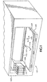
- FIG. 1 An exemplary inkjet hard copy apparatus, a computer printer 101, is shown in rudimentary form in FIG. 1.
- a printer housing 103 contains a platen 105 to which input print media 107 is transported by mechanisms as would be known in the state of the art.
- a carriage 109 holds a set 111 of individual print cartridges, one having cyan ink, one having magenta ink, one having yellow ink, and one having black ink.
- inkjet "pens” comprise semi-permanent printhead mechanisms having at least one small volume, on-board, ink chamber that is sporadically replenished from fluidically-coupled, off-axis, ink reservoirs; the present invention is applicable to both inkjet cartridges and pens.
- the carriage 109 is mounted on a slider 113, allowing the carriage 109 to be scanned back and forth across the print media 107.
- the scan axis, "X,” is indicated by arrow 115.
- ink drops can be fired from the set 111 of print cartridges onto the media 107 in predetermined print swath patterns, forming images or alphanumeric characters using dot matrix manipulation.
- the dot matrix manipulation is determined by a computer (not shown) and instructions are transmitted to an on-board, microprocessor-based, electronic controller (not shown) within the printer 101.
- the ink drop trajectory axis, "Z,” is indicated by arrow 117.
- the media 107 is moved an appropriate distance along the print media axis, "Y,” indicated by arrow 119 and the next swath can be printed.
- FIGS. 2 and 2A An exemplary thermal inkjet cartridge 210 is shown in FIGS. 2 and 2A.
- a cartridge housing, or shell, 212 contains an internal reservoir of ink (not shown).
- the cartridge 210 is provided with a printhead 214, which may be manufactured in the manner of a flex circuit 218, having electrical contacts 220.
- the printhead 214 includes an orifice plate 216, having a plurality of miniature nozzles 217 constructed in combination with subjacent structures leading to respective ink ejectors, which in thermal inkjet implementations are realized as heating elements (generally electrical resistors), that are connected to the contacts 220; together these elements form a printhead array of "drop generators" one of which is shown in the cross sectional detail of FIG. 2B and described in exemplary U.S.
- FIG. 2A depicts a simplified commercial design having an array of nozzles 217 comprising a layout of a plurality of single nozzle drop generators arranged in two parallel columns. Thermal excitation of ink via the heating elements is used to eject ink drops through the nozzles onto an adjacent print medium (see FIG. 1, element 107).
- exemplary commercial product such as the Hewlett-Packard DeskJet tm printer, model 722, one hundred and ninety-two (192), single nozzle, drop generators are employed to allow 300 dpi print resolution, however greater print resolution is available in other commercially available products.
- a conventional drop generator which can be utilized in the printhead 214 is shown in the cross section through one of the drop generators in FIG. 2B.
- the orifice plate 216 is penetrated by a nozzle 217 extending from an ink entrance port opposite a heating element 403 to an ink exit orifice. Ink is expelled from the exit orifice and is deposited as an ink drop in a target pixel 230 on the print medium 107.
- Nozzle configurations are design factors that control droplet size, velocity and trajectory of the droplets of ink in the Z-axis.
- the standard drop generator configuration has one orifice and is fired in either a single-drop per pixel or multi-drop per pixel print mode.
- one ink drop is selectively fired from each nozzle 217 from each print cartridge 210 toward a respective target pixel on the print media 107 (that is, a target pixel might get one drop of yellow from a nozzle and two drops of cyan from another nozzle in successive scans of the carriage to achieve a specific hue); in the multi-drop mode to improve saturation and resolution two sequential droplets of yellow and four of cyan might be used for that particular hue which might be done on one pass of the carriage.
- a target pixel shall mean a pixel which a drop generator is traversing as an inkjet printhead is scanned across an adjacent print medium, taking into consideration the physics of firing, flight time, trajectory, nozzle configuration, and the like as would be known to a person skilled in the art; that is, in a conventional printhead it is the pixel at which a particular drop generator is aiming; as will be recognized based on the following detailed description, with respect to the present invention, the target pixel may differ in location from a pixel on which the drop generator of the present invention forms dots; that is, dots may be formed in pixels other than the currently traversed pixel, i.e., other than the traditional target pixel .))
- the resulting dot on the print media is approximately the same size and color as the dots from the same and other nozzles on the same print cartridge.
- a drop generator comprises a plurality of nozzles for ejecting ink. Comparing FIGS. 3A-C and 4A-B to FIGS. 2, 2A and 2B, it will be recognized that in a multi- nozzle drop generator design, the orifice plate can have a variety of layout configurations for each drop generator. In one commercial embodiment, a printhead with 192 nozzles could be replaced with a printhead having 192 sets of four nozzles (768 nozzles in all). Note that since the number of heating elements has not been changed from the construct depicted in FIGS. 1 - 2B to achieve the configurations in FIGS. 3A - 3C and FIG. 4B, a retrofit using the same controller is possible.
- a drop generator 401 is formed using, for example, known laser ablation construction (see Background section and Schantz et al. U.S. Patents, supra ), having a heating element, resistor 403, located in an ink firing chamber 405.
- nozzles 407, 409, 411, 413 are cut through a manifold 415.
- Each nozzle 407, 409, 411, 413 is tapered from an ink entrance diameter, "D,” 417, superjacent the heating element 403 to a distal, narrower, ink drop exit diameter, "d,” 419.
- FIGS. 3A, 3B, 3C and 4B exemplifies that a variety of design relative configurations are possible (the examples are not intended to limit the scope of the invention to only the shown layouts as others, including both even and odd number of nozzle/orifice set arrays and combinatorial nozzle/orifice sets will be apparent to those skilled in the art).
- a specific optimal layout may be dependent upon many apparatus design factors, including scan velocity, ink composition, ink droplet flight time, flight distance between the orifice plate and the media, and the like as would be known to a person skilled in the art.
- the nozzles of an ink ejector are arranged such that the droplets expelled therefrom diverge in flight from the nozzle to the medium.
- This embodiment allows the pitch of the heater resistor to be arranged such that the heater resistors are disposed closer together, no longer limited by the position of the nozzles. This allows heater resistors, using present resistor and substrate design rules, to be positioned on 600 dpi pitches.
- the mix of nozzles per drop generator need not be a constant throughout the array for a given color. That is, a first ink ejector may have three nozzles and another ink ejector in the same array may have six nozzles. Similarly, the location and symmetry of nozzles in ink ejectors with the same number of nozzles may vary. Furthermore, the ink volume ejected by each nozzle may be designed to be different to achieve desirable image quality.
- each exit orifice has an exit orifice areal dimension sized to eject a droplet that will create a dot on the target medium that is less than or equal to the integer 1 divided by the number of orifices per drop generator times the areal dimension of a pixel (1/n) • P a , where "n" is the number of orifices per drop generator and "P a " is the area of a pixel to be printed
- each exit orifice is sized to produce a dot whose area is equal to or less than 1/3 times the area of a pixel, e.g., (1/3) • (1/300) 2 sq.
- each exit orifice is sized to produce a dot whose area is equal to or less than (1/4) • (1/300) 2 sq. in., etc. This relationship can vary, however, depending upon other design parameters of the orifices. It is a feature of the present invention that, regardless of the orifice exit area, the simultaneously generated ink droplets be distributed as dots onto an adjacent print medium as sets of dots having an area less than or equal to the product of the dividend of one divided by the number of nozzles and the area of the target pixel.
- area dot ⁇ (1/n) • P a where n is the number of nozzles per drop generator producing a dot and P a is the area of a target pixel to be printed.
- a dot diameter of less than or equal to approximately twenty to twenty-five microns is desirable.
- at least one dot will lie outside the target pixel and, in a favored embodiment, all dots will be outside the target pixel.
- droplets are spaced by twenty to twenty-five microns, they have become invisible to the naked eye. See, for example, FIGS 9A-9C.
- Each drop generator is designed so that the light absorption of the ink ejected per firing is, in total, approximately that which would have occurred in a corresponding ink drop ejection from a conventional drop generator onto the target pixel - but it is spread out in fine dots over a larger area than the single pixel of the conventional single drop technique.
- the distribution of these simultaneously fired droplets over an area larger than the conventional area offers advantageous printing characteristics.
- a printhead has sets of drop generators and all or some of the drop generators having a plurality, for example four, simultaneously firing nozzles. The nozzles are sized and arranged to produce resultant dots covering approximately the same total area of the printed medium as the conventional single pixel.
- the four simultaneously ejecting nozzles direct the droplets toward the medium in a fashion that produces a spaced apart deposition of dots.
- a predetermined amount of uninked medium appears between the dots. Since the dots are placed on the medium over an area greater than the single pixel, the apparent light absorption per unit area of the simultaneously fired dots will be perceived as less than the light absorption per unit area of a single dot formed in the target pixel from a conventionally ejected drop.
- each simultaneously ejected ink droplet is expelled with a predetermined drop weight (W) which is established within reasonable limits of tolerance by the well known interactions of inkjet ejection mechanics.
- W drop weight
- the number of nozzles is established as a fixed number, n, which in a preferred embodiment is four.
- the total ink drop weight ejected by one drop generator for one ejection event is therefore (n • W). If a single drop having an equivalent drop weight, (n • W), were conventionally deposited as a single dot in a target pixel, the light absorption of that single dot in the target pixel would be a certain value.
- the sum of the total light absorption of the dots resulting from the n simultaneously ejected droplets will be approximately equal to that of the dot resulting from the single, conventional, dot.
- the simultaneously ejected droplets result in dots dispersed over an area greater than a single pixel.
- the sum of the light absorption of all of the dots resulting from the simultaneously ejected droplets within any given pixel can be less than that of the conventionally deposited dot in the target pixel.
- n • A d ⁇ A c total deposition and n • A d ⁇ A c
- a d is the light absorption of one dot resulting from a plurality of n droplets simultaneously expelled from n ink ejecting nozzles
- W is the drop weight of each of the n droplets
- a c is the light absorption of the conventionally deposited drop having a drop weight of (n • W).
- the drop weights for each of the simultaneously expelled droplets from the same drop generator are not required to have identical drop weights.
- the sum of the absorptions of the dots formed by a plurality of n simultaneously expelled droplets is greater than that of the single dot formed by a conventionally expelled drop having a weight equal to the sum of n droplets.
- Media to be printed upon, particularly paper has a wide range of characteristics that affect inkjet printing. See, for example, Donald J. Palmer et al., "Ink and Media Development for the HP Paintjet Printer", Hewlett-Packard Journal, August 1988, pp. 45-50; David L. Lee et al., "Engineering an Ink Jet Paper What's Involved?”, Recent Progress in Ink-Jet Technologies, Society for Imaging Science and Technology, 1996, pp. 247-253; and J.
- FIGs. 9A - 9C Printing operation in accordance with the present invention is depicted in FIGs. 9A - 9C, showing a contiguous set of nine arbitrary pixels, 901 - 909, from a full grid overlay of an image to be printed.
- This depiction is greatly magnified; in commercial designs each pixel generally will be 1/300 inch by 1/300 inch or smaller).
- the firing of a single ink ejector of four nozzles as shown in FIG. 5 is described in order to achieve a dot fill of more than one pixel 905.
- a central pixel 905 of this grid subsection is to be essentially covered with ink.
- FIG. 9A - 9C shows a contiguous set of nine arbitrary pixels, 901 - 909, from a full grid overlay of an image to be printed.
- in the first scan pass four ink droplets deposit dots 911 about pixel 901 in accordance with instructions from the printer controller from one set of nozzles (e.g. nozzles 407", 409", 411", 413" as shown in FIG. 5).
- nozzles e.g. nozzles 407", 409", 411", 413" as shown in FIG. 5.
- the depiction of the dot sizes in FIGS. 9A-9C not withstanding, the area of the medium covered by any particular simultaneously ejected dot is defined by the foregoing area dot ⁇ (1/n) • P a .
- a rotated nozzle architecture described below, simultaneously deposits a dot in each of pixels 902 and 906, as shown in FIG. 9A, and in two pixels outside the exemplary grid area 901-909.
- dots 912 are deposited, including a first ink dot in the upper left quadrant of the exemplary pixel 905 and dots in pixels 901 and 903.
- dots 913 are deposited, including dots in pixels 902 and 904.
- the complexity of the firing algorithm during this first pass is dependent upon the image being produced and the full construction of the printhead implementation with many pixels in a nozzle array wide swath are being inked simultaneously, including drop-on-drop mixing of primary color inks to produce all of the hues and luminance ratios of the image that are required to reproduce the image faithfully.
- the media is shifted in the Y direction, perpendicular to the translation direction of the print head, enabling the printing of a second swath during the next scan pass across the print medium.
- FIG. 9B depicts a second pass, for example in the -X direction from right to left, that first deposits four ink dots 914 about pixel 904, including an ink dot in the upper right quadrant of the target pixel and dots in pixels 903 and 909.
- four dots 915 are deposited, including dots in the pixels 902, 904, 906 and 908.
- four dots 916 are deposited, including a third ink dot in the lower left quadrant of the exemplary pixel 905, and dots in pixels 901 and 907.
- FIG. 9C depicts a third pass, for example from left to right.
- Four ink dots 917 are deposited about pixel 907, including dotting pixels 906 and 908 when the drop generator set is above pixel 907.
- four dots 918 are deposited, including a fourth ink dot in the lower right quadrant of the exemplary pixel 905 and dots in pixels 907 and 909. Note that at this point in the third pass, the region around exemplary pixel 905 is filled via this bi-directional scanning method.
- dots 919 being deposited about pixel 909.
- Each of the droplets of a simultaneously ejected set produces a dot having a light absorption value of approximately one divided by the number of droplets per ink ejector multiplied by the absorption value of a conventional drop in the target pixel, given the same ink. That is, A d ⁇ (1/n) • A c , where n is the number of droplets simultaneously ejected per ink ejector and A c is the absorption of a conventionally placed drop in the target pixel, when area dot ⁇ (1/n) • P a .
- the positioning of the ink droplets as they are deposited upon the medium are structured to give special results which enhance printing characteristics and eliminate Moiré patterns and hue shifts which otherwise can occur.
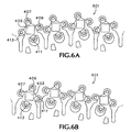
- FIG. 5 A first preferred embodiment of a partial orifice plate array 501 of four nozzle ink drop generators is shown in FIG. 5 (three sets of a total array), referred to hereinafter as a "right rotated quad architecture.”
- the nozzles 407, 409, 411, 413 are all oriented in quadrants orthogonally set about a geometric center point of the resistor 403 (viz., the geometric center point of the drop generator and relative to the scan axis, X, and the print axis, Y) and all of the droplets fall completely within the target pixel.
- a geometric center point of the resistor 403 viz., the geometric center point of the drop generator and relative to the scan axis, X, and the print axis, Y
- FIGS. 5 and 6A show a right rotated quad architecture of the nozzles around the central heating element
- FIG. 6B demonstrates a left rotation of the nozzles 407 - 413" about the centrally located heating elements 403 - 403".
- combinations of rotations and the use of different rotations affects print quality by reducing clustering of two secondary colors near each other, which clustering results in a very dark spot with nearby white, thereby giving a grainy appearance.
- Having different patterns for each color results in a more frequent placement of, for example, cyan and magenta adjacent to each other rather than atop each other in a mid-density blue tone. This results in less grainy sky images, in the present example. Similar effects occur in mid-range flesh tones employing magenta and yellow.
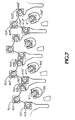
- FIG. 7 depicts an alternative embodiment where ink drop generators similar to FIG. 5 are employed with each nozzle 407 - 413" having a separate heating element 403 1 ' - 403 4 ' through 403" 4 .
- FIG. 7 shows a right rotation about a geometric center point of the drop generator indicative of the intersection of planes parallel to the X and Y axes
- FIG. 8 demonstrates a left rotation of the nozzles 407 - 413" and the individual heating elements 403 1 ' - 403 3 ".
- the contiguous set of pixels, 901 - 909, from a full grid overlay of an image are to be printed.
- the firing will be algorithmically controlled and that some or all of the selected sets of nozzles in the array will fire four ink droplets of an appropriate color during each scan in the X-axis (arrow 115), creating a printhead array wide swath equal to the length of the array in the Y-axis (arrow 119) in accordance with the firing signals generated by the print controller, for example, this could be a one inch or smaller pen swath up to a page length swath.
- ink dots 911 are deposited in pixels 902 and 906 and in two pixels outside the exemplary grid area 901-909.
- four dots 912 are deposited, including a first ink dots in the upper left quadrant of the exemplary yellow pixel 905 and dots in pixels 901 and 903.
- four dots 913 are deposited, including dots in pixels 902 and 904.
- a second swath can be printed during a next scan pass across the print medium.
- a commercial implementation having a plurality of ink ejectors on a printhead deposits dots into adjacent pixels such that a single column of adjacent pixels essentially as wide as the printhead will have dots deposited simultaneously, or nearly simultaneously, from independently activated ink ejectors).
- FIG. 9B depicts a second pass, from right to left, pass 2 , that first deposits four ink dots 914 about pixel 904, including an ink dot in the upper right quadrant of the target pixel and dots in pixels 903 and 909.
- four dots 915 are deposited, including dots in the pixels 902, 904, 906 and 908.
- four dots 916 are deposited, including a third ink dots in the lower left quadrant of the exemplary pixel 905, and dots in pixels 901 and 907.
- FIG. 9C depicts a third pass, from left to right, pass 3 .
- Four ink dots 917 are deposited about pixel 907, including placement in pixels 906 and 908 when the drop generator set is above pixel 907 in the Z axis (FIG. 1, arrow 117).
- four dots 918 are deposited, including a fourth ink dots in the lower right quadrant of the exemplary pixel 905 and dots in pixels 907 and 909. The process continues with drops 919 being deposited about pixel 909.
- CMYK inkjet hard copy apparatus employs one tri-color print cartridge for CMY inks with subsets of the array of nozzles each coupled to specific color ink reservoir and a separate black ink print cartridge (e.g., a standard, single nozzle configuration).
- a separate black ink print cartridge e.g., a standard, single nozzle configuration.
- FIGS. 10A - 10D color samples of a facial image, eye region, are provided as FIGS. 10A - 10D.
- FIGS. 10A - 10D These figures are a plain paper copy of a subsection prints and at a ten times magnification. The eye and a band of yellow makeup shown was each created from an original image by using four different computer generated virtual printing methodologies and the comparison prints made using a Hewlett-Packard DeskJetTM printer, model 850.
- FIG. 10A is a rendering of such a sample print as can be made with a conventional single nozzle printhead, 300 dpi printer;
- FIG. 10B from a print made on a conventional single nozzle printhead, 600 dpi printer;
- FIG. 10C from a print produced by experimental computer modeling using a 300 dpi printhead in accordance with the present invention using a nozzle layout configuration for CMYK inks in a right rotated quad architecture ("CMYK R-RotQuad") as shown in FIG. 5; and, FIG. 10D from a 300 dpi printhead in accordance with the present invention using nozzle array layout configuration for cyan ink in a left rotated orientation (“CL-”) as shown in FIG. 6B and magenta and yellow inks nozzle array layout configurations in a right rotated architecture ("MYK-R-RotQuad”) as shown in FIG. 5.
- CL- left rotated orientation
- MYK-R-RotQuad magenta and yellow inks nozzle array layout configurations in a right rotated architecture
- FIG. 10A shows a noticeable grain; that is, even in the highest resolution area of the iris, individual dots are very apparent to the unaided eye. Only in the center of the pupil, where black saturation is achieved, do the individual dots disappear. Luminance transition regions, e.g., above the eyeball and to the viewer's right side where yellow dots are dominant, are discontinuous rather than smooth (compare FIG. 10B).
- FIG. 10B shows a high resolution, 600 dpi, print with rich color saturation, smooth tonal transition, and markedly reduced granularity, with the reduced size individual dots showing quantization effects mostly in transition zones toning and the whites of the eyes.
- FIG. 10D Comparing FIG. 10D to FIGS. 10A and 10B, the same observations can be made as were made with respect to FIG. 10C. While FIGS. 10C and 10D are very close to each other in overall print quality, FIG. 10D has an overall sharpness that appears to be closer to FIG. 10B; in other words, the resolution appears to be slightly closer to the 600 dpi sample print.
- FIG. 10D has less noticeable diagonal banding in the "white flash region" of the iris than does FIG. 10D.
- This technique also is effective at masking Moiré patterns (an undesirable banding artifact in which, for example, two patterns having a different periodicity and/or orientation are overlain) that might result from color plane misalignment as the printhead traverses the medium, possibly in successive passes.
- Alternate designs may employ three separate rotations of the CYM inks to further optimize print quality and eliminate unwanted repeating patterns such are Moiré patterns. Additional nozzle placements and orientations may also be employed within a single color to further optimize print quality.
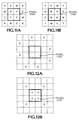
- FIG. 11A An example of a specific advantageous printing scheme is shown in FIG. 11A.
- a combination of nozzle rotations in a printhead is shown in order to direct four yellow ink droplets, represented by capital Y's in the drawing, toward a target pixel 1101 with other drops falling in accordance with a right rotated cyan nozzle cluster, represented by capital C's, a left rotated magenta nozzle cluster, represented by capital M's, and black placed at the outermost corners fired from a separate printhead.
- This arrangement is desirable because it reduces granularity in the printed image.
- Yellow ink generally has the lowest luminance and would have less perceived granularity due to the four yellow droplets located at the pixel center.
- FIG. 11A illustrates a superimposed schematic of the nozzle patterns for the ink ejectors for cyan (C), magenta (M), yellow (Y), and black (K) overlaid on a target pixel 1101.
- the cyan ejector employs only cyan nozzles in the positions shown. The other colors are arranged similarly.
- This design at least for cyan and magenta, resembles the rotated and counter rotated quads patterns of FIG. 6. Note that, when printing, if the cyan pattern were displaced to the right relative to, for example the magenta pattern, in the horizontal direction by one-half of a dot row, the top C-M pair would overlap less and the bottom pair would overlap more thereby resulting in no hue shift. The same is true for all color pairs employing this improvement. At the same time, overall granularity is reduced in mid tones because there are no large regions of overlapping colors.
- FIG. 11B has the same properties as FIG. 11A with regard to hue shift and granularity reduction, but places black at the center of the pixel. This allows one to print high spatial frequencies of black. Since composite black is far more frequently used in images than true black, one can have low granularity mid tones and sharp text and edges. It is possible that a printhead depositing a conventional single block dot within pixel 1101 would be used, for example, to avoid nozzle clogging by pigment-colored black ink or to obtain better black acuity. Nevertheless, a preferred embodiment employs a multiple nozzle black ink ink ejector.
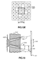
- FIG. 12A through 12E demonstrates an example of the more complex implementation scheme which can be devised in accordance with the present invention.
- FIGS. 12A through 12D show that as scanned, an appropriately constructed printhead can lay down super pixels in patterns such that as consecutive rows are printed, the super pixels are layered, C, Y, M, K to produce a pattern as shown in FIG. 12E. Actual nozzle firing and dot deposition will of course be based on the image being duplicated.
- the present invention speeds throughput significantly due to the decreased nozzle size since refill time is proportional to the capillarity force which is inversely proportional to the radius of the bore of the nozzle.
- a 300 dpi inkjet printer operates at about five kHz
- a 600 dpi printer operates at about twelve kHz.
- the deposition of the smaller droplets in accordance with the apparatus and method of the present invention is estimated to allow operating at approximately 30 kHz at 300 dpi but without the need for high data rates that multi-drop mode, high resolution printing requires.
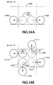
- FIG. 13 depicts a cross section of an alternative drop generator taken at a similar location as section line A-A of FIG. 3B.
- the axes, or boresights 1301, 1302, of the nozzles 411', 413' are angled away from a perpendicular 1303 from the plane of heater resistor 403' by an ejection angle ⁇ .
- An ink droplet ejected from each of the angled nozzle results in a dot on the medium displaced from the normal by a distance, m, and therefore places the dot outside of the target pixel 230.
- m a distance
- the ejection angle ⁇ is approximately 2° consistent with FIG. 14 but can vary depending upon the distance of the ejecting nozzle boresight from the centerline of the ink ejecting heater resistor centerline. It is expected that alternative embodiments will efficiently utilize ejection angle ⁇ values ranging from 0° to 10°. Other techniques of causing the expelled droplet from each ejecting nozzle to deviate from a direction of flight perpendicular to the surface of the orifice plate of the printhead may also be used.
- a nozzle asymmetry or a distortion in the nozzle opening having a sharp radius of curvature, or a radial notch in the outer surface opening of the nozzle may be used to disperse the dots in and around the target pixel.
- FIG. 14A The resulting dots deposited on the medium are depicted in FIG. 14A.
- One target pixel 230 is shown in full in broken line. Portions of the adjacent pixels are also shown.
- a normally positioned ink dot placed within pixel 230 is illustrated in broken line and referenced as 1403.
- the ink dot is actually placed as shown as dot 1405.
- a normal placement of dot 1407 is, as a result of the angled nozzle, deposited as dot 1409.
- Quad rotation as described above, is realized by moving the direction ejection angle ⁇ takes from the scan axis, X. As illustrated in the dot deposition of FIG.
- the nozzle ejecting the droplet in the placement of dot 1405 is angled in the direction of +X;
- the nozzle ejecting the droplet resulting in dot 1409' is angled in the direction, translation angle ⁇ 1 , of -90° from +X;
- the nozzle ejecting the droplet resulting in dot 1411 is angled in the direction, ⁇ 2 , of +90° from +X;
- the nozzle ejecting the droplet resulting in dot 1413 is angled in the direction, ⁇ 3 , of +180° from +X (i.e., -X).
- other increments of rotation both positive and negative as well as values which place the dots within the target pixel, can be utilized to place dots in a manner which provides useful print characteristics.
- the present invention provides a printhead design and ink drop deposition methodology using that design which provides superior print quality while employing techniques generally associated with low resolution inkjet printing. Printhead mechanical and electrical operational requirements are also facilitated.
- a set of nozzles per each drop generator is not limited to two, three or four.
- a hexagonal array reduces the total ink deposited by approximately thirty percent.
- a combination of using some hexagonal sets of nozzles used for a black filled area with other configurations for other color inks can be designed into specific printheads.
Landscapes
- Physics & Mathematics (AREA)
- Geometry (AREA)
- Ink Jet (AREA)
- Particle Formation And Scattering Control In Inkjet Printers (AREA)
Claims (2)
- Ein Tintenstrahldruckkopf mit einem Array von Tropfengeneratoren zum Ausstoßen von Tinte, um Punkte auf einem Druckmedium zu bilden, der folgende Merkmale aufweist:eine Mehrzahl von Tintenausstoßdüsen (217), die einem Tropfengenerator des Arrays von Tropfengeneratoren zugeordnet sind, so daß jede Düse der Mehrzahl von Tintenausstoßdüsen im wesentlichen gleichzeitig ein Tintentröpfchen ausstößt, wenn der Tropfengenerator aktiviert ist; undwobei die Mehrzahl von Tintenausstoßdüsen jeweils eine Düsenachse (1301, 1202) aufweisen, die die Zielsicht von jeder Düse definieren, und die Düsenachsen von einer Senkrechte, die von einer Ebene der Tintenausstoßvorrichtung gezogen ist, um einen Ausstoßwinkelwert (ϑ) weggeneigt sind, um einen Punkt zu erzeugen, der außerhalb eines Zielpixels um einen Abstand versetzt ist, der auf den Ausstoßwinkel bezogen ist, bei einem Düsentranslationswinkel Φa, der sich von dem von jeder anderen geneigten Düsenachse unterscheidet, gemessen von einer vorbestimmten Bewegungsrichtung entweder des Tintenstrahldruckkopfs oder des Druckmediums relativ zueinander, wobei der Düsentranslationswinkel der Rotationswinkel einer Düse im Hinblick auf die vorbestimmte Bewegungsrichtung ist, und wobei die Mehrzahl von Tintenausstoßdüsen angeordnet ist, um jedes Tröpfchen, das während einer ersten Aktivierung des einen Tropfengenerators zum Druckmedium ausgestoßen wird, zu lenken und um eine Mehrheit von resultierenden Punkten auf dem Druckmedium außerhalb des Zielpixels (230) zu plazieren, das gegenüber dem Tropfengenerator angeordnet ist, wobei das Zielpixel ein Bereich auf dem Medium ist, auf dem ein oder mehrere ausgestoßene Tropfen mit einer Flugbahn entlang der Senkrechten einen oder mehrere zugeordnete Tropfen aufbringen würden.
- Ein Verfahren zur Tintenstrahldruckkopf-Herstellung, bei dem der Druckkopf ein Array von Tropfengeneratoren verwendet, um Tinte auszustoßen, um Punkte auf einem Druckmedium zu bilden, wobei das Verfahren folgende Schritte aufweist:Bilden eines ersten Tropfengenerators des Arrays von Tropfengeneratoren von einer Tintenausstoßvorrichtung und einer Öffnungsplatte (216);Bilden einer Mehrzahl von Düsen (217), die dem ersten Tropfengenerator zugeordnet sind, sich durch die Öffnungsplatte von einem Eingangstor, das sich benachbart zur Tintenausstoßvorrichtung befindet, zu einer Ausgangsöffnung erstreckend, wobei die Mehrzahl von Düsen angeordnet ist, um die Tinte im wesentlichen gleichzeitig auszustoßen, wenn die Tintenausstoßvorrichtung aktiviert wird, wobei jede Düse der Mehrzahl von Düsen eine Düsenachse (1301, 1302) aufweist, die die Zielsicht der Düse definiert; undNeigen einer Mehrheit der Düsenachsen weg von einer Senkrechte, die von einer Ebene der Tintenausstoßvorrichtung gezogen ist, um zumindest einen Ausstoßwinkelwert (ϑ), so daß eine Mehrheit der Punkte, die durch Tröpfchen gebildet werden, die im wesentlichen gleichzeitig von der Mehrheit von Düsen des ersten Tropfengenerators ausgestoßen werden, wenn der erste Tropfengenerator aktiviert wird, auf dem Druckmedium außerhalb eines Zielpixels um eine Entfernung, die auf den zumindest einen Ausstoßwinkel bezogen ist, bei einem Translationswinkel Φa, von einer vorbestimmten Bewegungsrichtung des Tintenstrahldruckkopfs und des Druckmediums relativ zueinander, aufgebracht werden, wobei jede Düsenachse in eine Richtung geneigt ist, die sich von jeder anderen geneigten Düsenachse unterscheidet, wobei das Zielpixel ein gegenüber dem Tropfengenerator angeordneter Bereich auf dem Medium ist, auf dem ein oder mehrere ausgestoßene Tropfen, die eine Flugbahn entlang der Senkrechten aufweisen, einen oder mehrere zugeordnete Tropfen aufbringen würden, und wobei der Düsentranslationswinkel der Rotationswinkel einer Düse im Hinblick auf die vorbestimmte Bewegungsrichtung ist.
Applications Claiming Priority (2)
| Application Number | Priority Date | Filing Date | Title |
|---|---|---|---|
| US240286 | 1999-01-29 | ||
| US09/240,286 US6155670A (en) | 1997-03-05 | 1999-01-29 | Method and apparatus for improved ink-drop distribution in inkjet printing |
Publications (2)
| Publication Number | Publication Date |
|---|---|
| EP1024007A1 EP1024007A1 (de) | 2000-08-02 |
| EP1024007B1 true EP1024007B1 (de) | 2002-10-16 |
Family
ID=22905938
Family Applications (1)
| Application Number | Title | Priority Date | Filing Date |
|---|---|---|---|
| EP00300569A Expired - Lifetime EP1024007B1 (de) | 1999-01-29 | 2000-01-26 | Verfahren und Apparat zur verbesserten Tintentropfenverteilung beim Tintenstrahldruck |
Country Status (4)
| Country | Link |
|---|---|
| US (1) | US6155670A (de) |
| EP (1) | EP1024007B1 (de) |
| KR (1) | KR100633973B1 (de) |
| DE (1) | DE60000585T2 (de) |
Cited By (1)
| Publication number | Priority date | Publication date | Assignee | Title |
|---|---|---|---|---|
| WO2004048103A1 (en) * | 2002-11-23 | 2004-06-10 | Silverbrook Research Pty Ltd | Thermal ink jet printhead with high nozzle areal density |
Families Citing this family (24)
| Publication number | Priority date | Publication date | Assignee | Title |
|---|---|---|---|---|
| US6257690B1 (en) * | 1998-10-31 | 2001-07-10 | Hewlett-Packard Company | Ink ejection element firing order to minimize horizontal banding and the jaggedness of vertical lines |
| US6402301B1 (en) | 2000-10-27 | 2002-06-11 | Lexmark International, Inc | Ink jet printheads and methods therefor |
| US7594507B2 (en) | 2001-01-16 | 2009-09-29 | Hewlett-Packard Development Company, L.P. | Thermal generation of droplets for aerosol |
| US6592203B1 (en) | 2002-02-11 | 2003-07-15 | Lexmark International, Inc. | Subcovered printing mode for a printhead with multiple sized ejectors |
| US7573603B2 (en) * | 2002-10-11 | 2009-08-11 | Avago Technologies Fiber Ip (Singapore) Pte. Ltd. | Image data processing |
| AU2006252329B2 (en) * | 2002-11-23 | 2007-02-22 | Zamtec Limited | A Unit cell of a Printhead on a Multi-Layered Substrate |
| US6669333B1 (en) | 2002-11-23 | 2003-12-30 | Silverbrook Research Pty Ltd | Stacked heater elements in a thermal ink jet printhead |
| US7207652B2 (en) * | 2003-10-17 | 2007-04-24 | Lexmark International, Inc. | Balanced satellite distributions |
| US7093918B2 (en) | 2004-04-16 | 2006-08-22 | Hewlett-Packard Development Company, L.P. | Double dotting for grain equalization |
| CN100503248C (zh) * | 2004-06-02 | 2009-06-24 | 佳能株式会社 | 头基板、记录头、头盒、记录装置以及信息输入输出方法 |
| US20060000925A1 (en) * | 2004-06-30 | 2006-01-05 | Maher Colin G | Reduced sized micro-fluid jet nozzle structure |
| US8152262B2 (en) * | 2004-08-06 | 2012-04-10 | Seccombe S Dana | Means for higher speed inkjet printing |
| US20060163563A1 (en) * | 2005-01-24 | 2006-07-27 | Kurt Ulmer | Method to form a thin film resistor |
| JP4835018B2 (ja) * | 2005-03-25 | 2011-12-14 | ソニー株式会社 | 液体吐出ヘッド及び液体吐出装置 |
| JP4855858B2 (ja) * | 2006-07-19 | 2012-01-18 | 富士フイルム株式会社 | 液体吐出ヘッド及び画像形成装置 |
| JP4936880B2 (ja) * | 2006-12-26 | 2012-05-23 | 株式会社東芝 | ノズルプレート、ノズルプレートの製造方法、液滴吐出ヘッド及び液滴吐出装置 |
| US8354062B2 (en) | 2007-06-15 | 2013-01-15 | Xerox Corporation | Mixing device and mixing method |
| US7938517B2 (en) * | 2009-04-29 | 2011-05-10 | Eastman Kodak Company | Jet directionality control using printhead delivery channel |
| US8091983B2 (en) * | 2009-04-29 | 2012-01-10 | Eastman Kodak Company | Jet directionality control using printhead nozzle |
| US8057011B2 (en) * | 2009-05-26 | 2011-11-15 | Hewlett-Packard Development Company, L.P. | Fluid dispensing device |
| JP6102308B2 (ja) | 2013-02-15 | 2017-03-29 | セイコーエプソン株式会社 | インクジェット記録方法、インクジェット記録装置 |
| US9272301B2 (en) | 2013-03-01 | 2016-03-01 | S. Dana Seccombe | Apparatus and method for non-contact manipulation, conditioning, shaping and drying of surfaces |
| WO2018015357A1 (en) * | 2016-07-18 | 2018-01-25 | Beaulieu International Group Nv | Multi-layered sheets suitable as floor of wall covering exhibiting a three-dimensional relief and a decorative image |
| US20220134736A1 (en) * | 2019-07-18 | 2022-05-05 | Hewlett-Packard Development Company, L.P. | Print control instructions |
Family Cites Families (24)
| Publication number | Priority date | Publication date | Assignee | Title |
|---|---|---|---|---|
| DE2949616C2 (de) * | 1979-12-10 | 1982-12-16 | Siemens AG, 1000 Berlin und 8000 München | Schreibkopf für Tintenmosaikschreibeeinrichtungen |
| JPS57185159A (en) * | 1981-05-11 | 1982-11-15 | Nec Corp | Ink jet recorder |
| US4621273A (en) * | 1982-12-16 | 1986-11-04 | Hewlett-Packard Company | Print head for printing or vector plotting with a multiplicity of line widths |
| US4550326A (en) * | 1983-05-02 | 1985-10-29 | Hewlett-Packard Company | Fluidic tuning of impulse jet devices using passive orifices |
| DE3477118D1 (en) * | 1984-04-27 | 1989-04-13 | Siemens Ag | Ink-writing apparatus reproducing multicolour characters and/or patterns |
| US5258774A (en) * | 1985-11-26 | 1993-11-02 | Dataproducts Corporation | Compensation for aerodynamic influences in ink jet apparatuses having ink jet chambers utilizing a plurality of orifices |
| US4914451A (en) * | 1987-06-01 | 1990-04-03 | Hewlett-Packard Company | Post-printing image development of ink-jet generated transparencies |
| JPS6414340A (en) * | 1987-07-06 | 1989-01-18 | Kaihara Textile | Pattern weaving method by shuttleless loom |
| CA1303904C (en) * | 1987-08-10 | 1992-06-23 | Winthrop D. Childers | Offset nozzle droplet formation |
| JPH02194961A (ja) * | 1989-01-23 | 1990-08-01 | Nec Corp | インクジェット記録ヘッド |
| US5583550A (en) * | 1989-09-29 | 1996-12-10 | Hewlett-Packard Company | Ink drop placement for improved imaging |
| US4967203A (en) * | 1989-09-29 | 1990-10-30 | Hewlett-Packard Company | Interlace printing process |
| US4999646A (en) * | 1989-11-29 | 1991-03-12 | Hewlett-Packard Company | Method for enhancing the uniformity and consistency of dot formation produced by color ink jet printing |
| US5196056A (en) * | 1990-10-31 | 1993-03-23 | Hewlett-Packard Company | Ink jet composition with reduced bleed |
| US6513906B1 (en) * | 1991-06-06 | 2003-02-04 | Canon Kabushiki Kaisha | Recording apparatus and recording method |
| US5369428A (en) * | 1992-06-15 | 1994-11-29 | Hewlett-Packard Corporation | Bidirectional ink jet printing |
| US5485180A (en) * | 1992-08-05 | 1996-01-16 | Hewlett-Packard Company | Inking for color-inkjet printers, using non-integral drop averages, media varying inking, or more than two drops per pixel |
| JP3161094B2 (ja) * | 1992-10-08 | 2001-04-25 | 富士ゼロックス株式会社 | インクジェット記録装置における記録方法 |
| EP0623473B1 (de) * | 1993-05-03 | 2003-07-23 | Hewlett-Packard Company, A Delaware Corporation | Gesteigerte Druckauflösung in der Ablaufachse des Wagens eines Tintenstrahldruckers |
| IT1270861B (it) * | 1993-05-31 | 1997-05-13 | Olivetti Canon Ind Spa | Testina a getto di inchiostro perfezionata per una stampante a punti |
| US5764256A (en) * | 1994-03-03 | 1998-06-09 | Brother Kogyo Kabushiki Kaisha | System and method for ejecting ink droplets from a nozzle |
| DE69603037T2 (de) * | 1995-03-08 | 1999-10-21 | Hewlett-Packard Co., Palo Alto | Tintenstrahldrucker |
| US5731827A (en) * | 1995-10-06 | 1998-03-24 | Xerox Corporation | Liquid ink printer having apparent 1XN addressability |
| US6099108A (en) * | 1997-03-05 | 2000-08-08 | Hewlett-Packard Company | Method and apparatus for improved ink-drop distribution in ink-jet printing |
-
1999
- 1999-01-29 US US09/240,286 patent/US6155670A/en not_active Expired - Lifetime
-
2000
- 2000-01-26 EP EP00300569A patent/EP1024007B1/de not_active Expired - Lifetime
- 2000-01-26 DE DE60000585T patent/DE60000585T2/de not_active Expired - Lifetime
- 2000-01-27 KR KR1020000004069A patent/KR100633973B1/ko not_active Expired - Fee Related
Cited By (8)
| Publication number | Priority date | Publication date | Assignee | Title |
|---|---|---|---|---|
| WO2004048103A1 (en) * | 2002-11-23 | 2004-06-10 | Silverbrook Research Pty Ltd | Thermal ink jet printhead with high nozzle areal density |
| US7086718B2 (en) | 2002-11-23 | 2006-08-08 | Silverbrook Research Pty Ltd | Thermal ink jet printhead with high nozzle areal density |
| US7303263B2 (en) | 2002-11-23 | 2007-12-04 | Silverbrook Research Pty Ltd | Thermal ink jet printhead with high nozzle areal density |
| US7441876B2 (en) | 2002-11-23 | 2008-10-28 | Silverbrook Research Pty Ltd | Inkjet printhead with suspended heater elements |
| US7597423B2 (en) | 2002-11-23 | 2009-10-06 | Silverbrook Research Pty Ltd | Printhead chip with high nozzle areal density |
| US7726780B2 (en) | 2002-11-23 | 2010-06-01 | Silverbrook Research Pty Ltd | Inkjet printhead having high areal inkjet nozzle density |
| US7824016B2 (en) | 2002-11-23 | 2010-11-02 | Silverbrook Research Pty Ltd | Pagewidth printhead arrangement with a controller for facilitating weighted ink drop ejection |
| US8287099B2 (en) | 2002-11-23 | 2012-10-16 | Zamtec Limited | Printhead having annular shaped nozzle heaters |
Also Published As
| Publication number | Publication date |
|---|---|
| US6155670A (en) | 2000-12-05 |
| KR20000076542A (ko) | 2000-12-26 |
| EP1024007A1 (de) | 2000-08-02 |
| KR100633973B1 (ko) | 2006-10-13 |
| DE60000585D1 (de) | 2002-11-21 |
| DE60000585T2 (de) | 2003-07-17 |
Similar Documents
| Publication | Publication Date | Title |
|---|---|---|
| EP1024007B1 (de) | Verfahren und Apparat zur verbesserten Tintentropfenverteilung beim Tintenstrahldruck | |
| EP0863020B1 (de) | Verfahren und Vorrichtung für verbesserte Tintentropfverteilung beim Tintenstrahldrucken | |
| EP0247179B1 (de) | Grauton-tintenstrahldruckvorrichtung | |
| US6310639B1 (en) | Printer printhead | |
| US5726690A (en) | Control of ink drop volume in thermal inkjet printheads by varying the pulse width of the firing pulses | |
| US6244687B1 (en) | Mixing overprinting and underprinting of inks in an inkjet printer to speed up the dry time of black ink without undesirable hue shifts | |
| US5997132A (en) | Method and apparatus for improving image quality | |
| US6834936B2 (en) | Ink jet printing apparatus and ink jet printing method | |
| EP0517520B1 (de) | Farbstrahlaufzeichnungsverfahren und Vorrichtung | |
| CN1209391A (zh) | 用喷墨打印机采用提高的水平分辨率来打印的方法 | |
| US6003970A (en) | Ink-jet recording apparatus and method | |
| US5975673A (en) | Image output method and apparatus for smoothing image data by manipulating dot sizes | |
| CN100569529C (zh) | 打印设备和打印方法 | |
| JPH08258291A (ja) | 混合解像度プリンタにおけるドットの位置合わせ方法及び装置 | |
| EP0649746A1 (de) | Tintenstrahldruckköpfe mit variablem Halbton-Betrieb | |
| JPH04361055A (ja) | インクジェット記録方法 | |
| JP3907685B2 (ja) | 画像形成装置 | |
| JP2000037864A (ja) | インクジェット印刷装置およびマスクパターン作成方法 | |
| JPH07117330A (ja) | カラーインクジェット記録方法及び記録装置 | |
| JP3067839B2 (ja) | インクジェット記録装置 | |
| JP3382548B2 (ja) | インクジェット記録装置および記録方法 | |
| JPH11216883A (ja) | 媒体表面に印刷する方法 | |
| JP2005119100A (ja) | 記録ヘッド |
Legal Events
| Date | Code | Title | Description |
|---|---|---|---|
| PUAI | Public reference made under article 153(3) epc to a published international application that has entered the european phase |
Free format text: ORIGINAL CODE: 0009012 |
|
| AK | Designated contracting states |
Kind code of ref document: A1 Designated state(s): DE FR GB IT |
|
| AX | Request for extension of the european patent |
Free format text: AL;LT;LV;MK;RO;SI |
|
| 17P | Request for examination filed |
Effective date: 20010105 |
|
| AKX | Designation fees paid |
Free format text: DE FR GB IT |
|
| 17Q | First examination report despatched |
Effective date: 20010319 |
|
| RAP1 | Party data changed (applicant data changed or rights of an application transferred) |
Owner name: HEWLETT-PACKARD COMPANY, A DELAWARE CORPORATION |
|
| GRAG | Despatch of communication of intention to grant |
Free format text: ORIGINAL CODE: EPIDOS AGRA |
|
| GRAG | Despatch of communication of intention to grant |
Free format text: ORIGINAL CODE: EPIDOS AGRA |
|
| GRAH | Despatch of communication of intention to grant a patent |
Free format text: ORIGINAL CODE: EPIDOS IGRA |
|
| GRAH | Despatch of communication of intention to grant a patent |
Free format text: ORIGINAL CODE: EPIDOS IGRA |
|
| GRAA | (expected) grant |
Free format text: ORIGINAL CODE: 0009210 |
|
| AK | Designated contracting states |
Kind code of ref document: B1 Designated state(s): DE FR GB IT |
|
| REG | Reference to a national code |
Ref country code: GB Ref legal event code: FG4D |
|
| REF | Corresponds to: |
Ref document number: 60000585 Country of ref document: DE Date of ref document: 20021121 |
|
| ET | Fr: translation filed | ||
| PLBE | No opposition filed within time limit |
Free format text: ORIGINAL CODE: 0009261 |
|
| STAA | Information on the status of an ep patent application or granted ep patent |
Free format text: STATUS: NO OPPOSITION FILED WITHIN TIME LIMIT |
|
| 26N | No opposition filed |
Effective date: 20030717 |
|
| REG | Reference to a national code |
Ref country code: GB Ref legal event code: 732E Free format text: REGISTERED BETWEEN 20120329 AND 20120404 |
|
| PGFP | Annual fee paid to national office [announced via postgrant information from national office to epo] |
Ref country code: IT Payment date: 20120124 Year of fee payment: 13 |
|
| PGFP | Annual fee paid to national office [announced via postgrant information from national office to epo] |
Ref country code: GB Payment date: 20121224 Year of fee payment: 14 |
|
| PGFP | Annual fee paid to national office [announced via postgrant information from national office to epo] |
Ref country code: FR Payment date: 20130305 Year of fee payment: 14 Ref country code: DE Payment date: 20121226 Year of fee payment: 14 |
|
| REG | Reference to a national code |
Ref country code: DE Ref legal event code: R119 Ref document number: 60000585 Country of ref document: DE |
|
| GBPC | Gb: european patent ceased through non-payment of renewal fee |
Effective date: 20140126 |
|
| REG | Reference to a national code |
Ref country code: DE Ref legal event code: R119 Ref document number: 60000585 Country of ref document: DE Effective date: 20140801 |
|
| PG25 | Lapsed in a contracting state [announced via postgrant information from national office to epo] |
Ref country code: DE Free format text: LAPSE BECAUSE OF NON-PAYMENT OF DUE FEES Effective date: 20140801 |
|
| REG | Reference to a national code |
Ref country code: FR Ref legal event code: ST Effective date: 20140930 |
|
| PG25 | Lapsed in a contracting state [announced via postgrant information from national office to epo] |
Ref country code: FR Free format text: LAPSE BECAUSE OF NON-PAYMENT OF DUE FEES Effective date: 20140131 Ref country code: GB Free format text: LAPSE BECAUSE OF NON-PAYMENT OF DUE FEES Effective date: 20140126 |
|
| PG25 | Lapsed in a contracting state [announced via postgrant information from national office to epo] |
Ref country code: IT Free format text: LAPSE BECAUSE OF NON-PAYMENT OF DUE FEES Effective date: 20140126 |