EP1400161A1 - System zur Erfassung von Eigenschaften von mit einer landwirtschaftlichen Erntemaschine geerntetem Erntegut - Google Patents
System zur Erfassung von Eigenschaften von mit einer landwirtschaftlichen Erntemaschine geerntetem Erntegut Download PDFInfo
- Publication number
- EP1400161A1 EP1400161A1 EP03102617A EP03102617A EP1400161A1 EP 1400161 A1 EP1400161 A1 EP 1400161A1 EP 03102617 A EP03102617 A EP 03102617A EP 03102617 A EP03102617 A EP 03102617A EP 1400161 A1 EP1400161 A1 EP 1400161A1
- Authority
- EP
- European Patent Office
- Prior art keywords
- combine
- sensor
- transport vehicle
- harvested
- weight
- Prior art date
- Legal status (The legal status is an assumption and is not a legal conclusion. Google has not performed a legal analysis and makes no representation as to the accuracy of the status listed.)
- Granted
Links
- 238000003306 harvesting Methods 0.000 claims abstract description 16
- 238000005259 measurement Methods 0.000 claims abstract description 11
- 230000005540 biological transmission Effects 0.000 claims abstract description 4
- 238000005303 weighing Methods 0.000 claims description 13
- 238000012546 transfer Methods 0.000 claims description 10
- 230000000977 initiatory effect Effects 0.000 claims 1
- 238000000034 method Methods 0.000 description 129
- 238000010586 diagram Methods 0.000 description 11
- 238000012790 confirmation Methods 0.000 description 10
- 238000004891 communication Methods 0.000 description 5
- 241001124569 Lycaenidae Species 0.000 description 3
- 238000013507 mapping Methods 0.000 description 2
- 241000408529 Libra Species 0.000 description 1
- 238000012544 monitoring process Methods 0.000 description 1
Images





Classifications
-
- A—HUMAN NECESSITIES
- A01—AGRICULTURE; FORESTRY; ANIMAL HUSBANDRY; HUNTING; TRAPPING; FISHING
- A01D—HARVESTING; MOWING
- A01D41/00—Combines, i.e. harvesters or mowers combined with threshing devices
- A01D41/12—Details of combines
- A01D41/127—Control or measuring arrangements specially adapted for combines
-
- A—HUMAN NECESSITIES
- A01—AGRICULTURE; FORESTRY; ANIMAL HUSBANDRY; HUNTING; TRAPPING; FISHING
- A01D—HARVESTING; MOWING
- A01D41/00—Combines, i.e. harvesters or mowers combined with threshing devices
- A01D41/12—Details of combines
- A01D41/127—Control or measuring arrangements specially adapted for combines
- A01D41/1271—Control or measuring arrangements specially adapted for combines for measuring crop flow
-
- G—PHYSICS
- G01—MEASURING; TESTING
- G01F—MEASURING VOLUME, VOLUME FLOW, MASS FLOW OR LIQUID LEVEL; METERING BY VOLUME
- G01F25/00—Testing or calibration of apparatus for measuring volume, volume flow or liquid level or for metering by volume
- G01F25/10—Testing or calibration of apparatus for measuring volume, volume flow or liquid level or for metering by volume of flowmeters
Definitions
- the invention relates to a system for recording properties of harvested with an agricultural harvester Crop, with a sensor attached to the harvester, the is operable to record properties of harvested crop and a second sensor spaced from the harvester, which is operable, also the properties of the Harvester to capture harvested crops, and with a Computing device that calibrates the measurement results of the first sensor by the measurement results of the second sensor allows.
- Combines generally have yield monitors around properties of agricultural products of interest determine when they are harvested.
- a typical yield monitor includes sensors such as a mass flow sensor and one Humidity Sensor. To get an accurate measurement of the yield get the mass flow sensor and the Moisture sensor to be calibrated periodically.
- the procedure calibration of a mass flow sensor usually involves (see US 5 369 603 A) harvesting grain, filling one Grain transport truck, truck or trailer and the comparison between the measured weight and a more accurate weight, the by means of a weighing system or a truck scale from one Grain dolly was won.
- a disadvantage with the prior art calibration techniques is that between the beginning and the end of the Calibration process can take a considerable amount of time, when a truck or trailer to a distant weighing machine moves. The farmer may also hesitate to harvest interrupt while receiving the current Weight values of the calibration load are waiting. During the time in that the trucks are away from the field, could be the Calibration factors for the mass flow sensor are considerable change. Grain tankers equipped with weighing systems can used to make a mass flow sensor lighter and calibrate more quickly manually. Many tankers are, however not equipped with weighing systems since the latter do not have them adds significant value.
- the current loading weight calibration is required manual entry into a display device (such as one of GreenStar display device sold by the applicant).
- the manual entry of the calibration information requires working time of the operator. If the operator fails the calibration performs sufficiently frequently, the accuracy of the Mass flow sensors drop because the car's load is on a larger average and therefore not on the last one Field conditions based. It is usually considered too viewed time consuming, the calibration factor after each loading manually update.
- the object on which the invention is based is seen in calibrating the measuring device to a harvesting machine simplify.
- the sensors can, for example, the humidity or the Record the weight (mass) of the crop.
- the latter can by Weighing of a transport vehicle on which the crop is loaded is measured, or the loading container of the transport vehicle become.
- the data recorded with the second sensor are processed by a transmitter of the transport vehicle wirelessly on the Transfer computing device. Arranging the measurement and the data can be transferred automatically (automatically) prompted to take place.
- the present invention provides a system and method for spaced and automatic calibration of sensors ready, such as the mass flow sensor in one Combine harvester yield monitor.
- the invention uses a wireless communication device on a combine harvester is installed and a spaced wireless communication device.
- the spaced-apart wireless communication device can be on a truck is installed that has a weighing system, a truck or semi-trailer, or any other Device installed, access to the desired information Has.
- the yield monitor takes over information during harvesting from the mass flow sensor and generates an estimate of the weight of the harvested product.
- the current weight of the harvested product is known (for example from the weighing system of the Tank truck or from a truck scale etc.)
- calibration information can include a calibration factor based on the current and relates the estimated weight.
- the Calibration information simply include information that is relates to the current weight. In this case, a Calibration factor calculated on the combine.
- the new Calibration factor based on the transmitted information can be applied to previously harvested grain loads to the Weighing yield and a more accurate representation of the yield on the To achieve field during all harvesting conditions.
- the spaced wireless communication device mounted on a truck or trailer
- the current weight information stored and later on the Combine harvesters are transferred (e.g. when the truck or Trailer is closer to the combine).
- the automatic calibration method according to the invention facilitates continuous updates of the calibration on one on the individual charge based base, which is a diminution the yield monitoring error results. Besides, they are measured yields of the harvested loads more accurately, since they are the reflect current crop conditions, as opposed to an average condition on which the last Calibration was carried out.
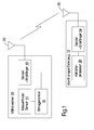
- Figure 1 is a block diagram a combine 10 and a grain transport vehicle 12.
- Das Grain transport vehicle 12 can be a unloading truck, truck, Trailer or another suitable grain-carrying vehicle his.
- Combine 10 has a first sensor Mass flow sensor 14 with a computing device having yield monitor 16 is connected.
- the yield monitor 16 is able to Estimated weight of the harvested grain based on the To provide information of the mass flow sensor 14. It is note that for the sake of clarity various others Sensors and components are not shown.
- the yield monitor 16 is with a transmitter and receiver 18 of a wireless Communication device connected, which in turn with an antenna 20th connected is.
- the grain transport vehicle 12 has a wireless transmitter and Receiver 24 connected to an antenna 26.
- the wireless transmitter and receiver 24 is with one Calibration processor 28 connected based on the current Weight of the grain in the grain transport vehicle 12 Calibration information generated.
- the wireless transmitter and receiver 18 of the combine 10 is able to provide information with the Transmitter and receiver 24 of the grain transport vehicle 12 exchange.
- the combine 10 When the combine 10 is harvesting a grain load, it estimates Yield monitor 16 the weight of the grain load based on the Information from the mass flow sensor 14. After harvested Grain has been transferred to the grain transport vehicle 12, it will Grain weighed by means of a second sensor, either by a Truck scale or on the grain transport vehicle 12, if there is Load weighing devices. That through the second Current weight of the grain is detected by the sensor Calibration processor 28 used to provide calibration information generate that on the combine 10 for use by the Yield monitor 16 for the purpose of calibrating the mass flow sensor 14 is transferred back.
- the calibration information can be a Calibration factor include, based on the current weight obtains an old calibration factor, and that from the yield monitor 16 estimated weight. Alternatively, the calibration information include only the current weight.
- Figures 2 to 5 are detailed flow diagrams in which an example of the method according to the invention is shown.
- Figures 2 to 5 are performed on the combine 10 Procedures generally shown on the left and the in Grain transport vehicle 12 procedures are carried out on the shown on the right.
- Figures 2 to 5 show only one example of an embodiment of the invention.
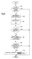
- FIG. 2 is a flow diagram in which the inclusion of a wireless connection between a combine 10 and a Grain transport vehicle 12 is illustrated.
- the method starts with step 30, in which the process finds the current calibration factor.
- step 32 a variable for a wireless connection to "false" set.
- the process starts on the grain transport vehicle 12 step 34 where an empty combine database is created becomes. It should be noted that the combine database May contain information for one or more combine harvesters.
- step 36 a variable for a wireless Connection set to "Wrong”.
- step 37 the Sender and receiver 18 of the combine 10 have a message meaning "connect”. If determined in step 38 then is that no message is received from the grain transport vehicle 12 the process goes back to step 32. This Loop continues until a reply message from Grain transport vehicle is received.
- step 39 the grain transport vehicle 12 receives the "Connect" message from the wireless transmitter and receiver 18 of the Combine 10 and the process moves to step 40.
- the process queries whether the distance between the Grain transport vehicle 12 and the combine 10 is smaller than a maximum desired distance (variable Max_Dist) and whether the difference in direction is less than a maximum desired Difference (variable max diff). If so, the process goes to step 42 where an acknowledgment signal is sent and (in step 44) is received by the combine 10. If so if not, the process moves to step 43 where an attempt is made to load the last combine 10 to calibrate (see Figure 6). At that time, a wireless connection between the combine 10 and the Grain transport vehicle 12 manufactured. Both on the combine 10 as well as on the grain transport vehicle 12 becomes the variable set to true for the wireless connection.
- FIG. 3 shows a flow diagram of the startup procedure for the wireless Connection.
- the combine 10 transmits its last calibration factor.
- step 52 that receives Grain transport vehicle 12 the calibration factor from the combine 10.
- step 54 the grain transport vehicle 12 transmits Confirmation signal from combine 10 in step 56 Will be received.
- step 60 the process queries whether the previous calibration information from the combine 10 is available is. If not, the process moves to step 82 which continues is described below. If previous calibration information from the combine 10, the process goes to step 62 in which the previous calibration factor is applied to the combine 10 is transmitted.
- step 64 the combine 10 receives the previous calibration factor.
- the Combine 10 in step 66 a confirmation signal.
- the Grain transport vehicle 12 receives this in step 68 Confirmation signal.
- the process goes to Step 70 over, in which the received calibration factor saved and linked with a load number.
- step 72 the process queries whether the last one Calibration factor was received. If that is the case, it goes Process to step 74 where the calibration factor is up the calibration factor of the last load is set.
- step 76 On the Grain transport vehicle 12, the process goes to step 76 above, in which a query is made as to whether the last load is calibrated has been. If so, the process moves to step 82. If not, the process moves to step 78 where the System informs the operator to stop and perform a calibration perform.
- FIG 4 is a flow chart a procedure to maintain the connection.
- the process queries whether the since the last received signal elapsed time greater than a threshold is (e.g. 7 seconds). If so, it is found that the Connection is lost and the process goes back to Step 32 of Figure 2.
- a threshold e.g. 7 seconds.
- the process queries whether the since the last received signal elapsed time greater than a threshold is (e.g. 7 seconds). If so, it is found that the Connection is lost and the process goes back to Step 36 of Figure 2.
- step 86 the process depends on whether the status of the discharge screw conveyor has changed. If so, the process goes to step 100 5 over. If not, the process asks at step 88 whether the time elapsed since the last transmission is greater than is a threshold (e.g. 2 seconds). If not, the Process returns to step 80. If so, the process goes to Step 90 over and a "check_connection" signal is sent transfer. The process goes on on the grain transport vehicle 12 Step 92 and asks if a message has been received. If not, the process goes back to step 82. If the signal "Check_connection" received in step 94 becomes step 96 transmitted a confirmation and in step 98 from the combine receive. The process on the grain transport vehicle 12 then goes back to step 82.
- a threshold e.g. 2 seconds
- FIG. 5 is a flowchart of the procedure of changing the Unloading screw conveyor status. If, back in step 86, it was found that the status of the discharge screw conveyor has changed, the process shown in Figure 5 carried out.
- the process shown in Figure 5 begins with Step 100 in which he queries whether the Unloading screw conveyor is in operation. If the Unloading screw conveyor is in operation (i.e. the Combine 10 has just started unloading grain) Process to step 102 in which the combine 10 is a Signal that the unloading screw conveyor is in operation, transfers.
- step 104 the grain transport vehicle 12 receives the signal for the activated discharge screw conveyor and transmits an acknowledgment signal (step 106).
- step 108 the combine 10 receives the confirmation signal and the The process goes back to steps 80 and shown in FIG 82.
- step 110 the Combine 10 a signal for an unloading screw conveyor that is switched off transfers.
- the combine also transmits 10, at step 112, an accumulated weight signal that is related to the estimated weight from the Yield monitor 16 was generated.
- steps 114 and 116 the grain transport vehicle 12 receives the signal for the switched off discharge screw conveyor and the signal for that accumulated weight.
- step 118 that transmits Grain transport vehicle 12 receives a confirmation signal in step 120 is received by the combine 10.
- step 122 the variable for the weight accumulated in the combine 10 is reset.
- step 124 On the grain transport vehicle 12, the process goes step by step 124 above, in which the loading data from the combine 10 can be saved.
- step 126 a Attempt made to calibrate the load (see Figure 6).
- Step 128 transmits the grain transport vehicle 12 Acknowledgment signal from combine 10 in step 130 Will be received.
- Step 128 transmits the grain transport vehicle 12 Acknowledgment signal from combine 10 in step 130 Will be received.
- the process goes back to that Steps 80 and 82 of Figure 4.
- FIG. 6 is a flow chart in which the process of Attempted calibration of the last load is shown. It should be noted that this process can be carried out before or after a wireless connection is established.
- the process begins in step 140, where it queries whether that is Grain transport vehicle 12 is stationary. If not, the ends Process. If the grain transport vehicle 12 is standing, the Process to step 142 where the current weight the grain transport vehicle 12 or its load is read. In the case of a grain transport vehicle 12 with weighing capability, the weighing system of the grain transport vehicle 12 the weight provide. In the case of a grain transport vehicle 12 that is on a truck scale is weighed, the weight is determined by the Libra provided. Next, in step 144, the Variable for the exact weight set to "True".
- step 146 the process asks if a previous weight is stored is. If not, the process ends. If a previous weight the process moves to step 148, in which the variable for the current weight to the final Weight minus the initial weight is set (i.e. the current weight of the grain is calculated since the measured Weights include the weight of the grain transport vehicle 12).
- step 150 the process asks if the last load of the Combine 10 was calibrated. If so, the process ends. If the last load on the combine 10 is not calibrated the process moves to step 152 where new calibration factor is calculated. The new calibration factor becomes equal to the old calibration factor, multiplied by the Ratio between the weight estimated by the combine 10 and the current weight calculated above. In step 152 the process ends.
- Figures 7 through 11 are flowcharts showing an example of the operation of the present invention primarily relates to the calibration of a combine 10.
- FIG. 7 is a flow chart in which the inclusion of a wireless connection between a combine 10 and a Grain transport vehicle 12 is illustrated.
- the method starts with step 160, in which a wireless Connection variable is set to "Wrong".
- the Grain transport vehicle 12 starts the process with step 162, in which an empty combine database is created. Moreover becomes a wireless connection variable in step 164 set to "false”.
- the transmitter transmits and Receiver 18 of the combine 10 sends a message with the meaning "Connect”. If it is determined in step 168 that no message was received from the grain transport vehicle 12, the process returns to step 160. This loop will continue until a response message from the grain transport vehicle 12 is received.
- step 170 the grain transport vehicle 12 receives the "Connect" message from the wireless transmitter and receiver 18 of the Combine 10 and the process moves to step 172.
- step 172 the process queries whether the distance between the Grain transport vehicle 12 and the combine 10 is smaller than a maximum desired distance (variable Max_Dist) whether the Direction difference less than a maximum desired difference (Variable Max_Diff) and whether it is on the left side of the Combine 10 is located. If so, the process goes to Step 174 in which an acknowledgment signal is sent and (in Step 168) is received by the combine 10. If not if so, the process proceeds to step 176, where one Attempt is made to load the last combine 10 calibrate. At this point there was a wireless connection between the combine 10 and the grain transport vehicle 12 manufactured. Both on the combine 10 and on the Grain transport vehicle 12 becomes a variable for a wireless Connection set to true (steps 178 and 180).
- FIG. 8 shows a flowchart of the start-up procedure for the Combine 10.
- the process queries whether that Weight of the combine 10 load is available. If not, the process moves to step 206 ( Figure 9), which is described below. If the weight of the load of the Combine 10 is available, the process continues to step 184 in which the weight of the current load on the Combine 10 is transmitted. In step 186 the Combine 10 the current weight. In response, the Combine 10 in step 188 an acknowledgment signal. The Grain transport vehicle 12 receives the confirmation signal in Step 190. On the combine 10, the process goes on Step 192 in which the current weight of the load is used Use in a revenue mapping process is transferred.
- Step 194 becomes a routine for calculating a new one Load calibration factor performed based on the current weight of the load.
- step 196 the process queries whether the last load was received. If so, the process moves to step 198 where the Calibration factor to the calibration factor of the last load is set. The process goes on the grain transport vehicle 12 to step 200 where the process queries whether the last load was weighed. If so, the process goes on Step 206 over ( Figure 9). If not, the process goes on Step 202 in which the system informs the operator to stop and weigh the load.
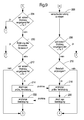
- FIG. 9 is a Flow chart of a procedure for maintaining the Connection.
- the process queries whether the since last received signal elapsed time greater than one Threshold is (e.g. 7 seconds). If so, is it determined that the connection has been lost and the process is going back to step 160 of FIG. 7. In step 206 this tries Grain transport vehicle 12 to weigh the load.
- the process queries whether the since the last received signal elapsed time greater than a threshold is (e.g. 7 seconds). If so, it is found that the Connection is lost and the process goes back to Step 164 of Figure 7.
- step 210 the process depends on whether the status of the discharge screw conveyor has changed. If so, the process goes to step 224 10 over. If not, the process asks in step 212, whether the time elapsed since the last transmission is greater than is a threshold (e.g. 2 seconds). If not, the Process returns to step 204. If so, the process goes to Step 214 over and a "Check_connection" signal is sent transfer. The process goes on on the grain transport vehicle 12 Step 216 and asks if a message has been received. If the process returns to step 206. If the signal "Check_connection" received in step 218 is in the Step 220 transmit an acknowledgment and in step 222 from Combine 10 received. The process on the Grain transport vehicle 12 then returns to step 206.
- a threshold e.g. 2 seconds
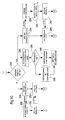
- FIG. 10 is a flowchart of the procedure of changing the Unloading screw conveyor status. If, back in step 210, it was found that the status of the discharge screw conveyor has changed, that in FIG. 10 process shown. The one shown in Figure 10 The process begins with step 224, in which it queries whether the Unloading screw conveyor is in operation. If the Unloading screw conveyor is in operation (i.e. the Combine 10 has just started unloading grain) Process to step 226 in which the combine 10 is a Signal that the unloading screw conveyor is in operation, transfers. In step 228, the grain transport vehicle 12 receives the signal for the activated discharge screw conveyor and transmits an acknowledgment signal (step 230).
- step 232 the combine 10 receives the confirmation signal and the Process goes back to steps 204 and 9 shown in FIG 206.
- the unloading screw conveyor is not in step 224 Operation (i.e. the combine 10 has just stopped, grain the process moves to steps 234 and 236, in which the combine 10 a signal for a switched off Unloading screw conveyor transmits and the variable for the im Combine 10 accumulated or accumulated weight is reset.
- this receives Grain transport vehicle 12 the signal for the switched off Unloading screw conveyor and stores the number in step 240 the loading of the combine 10.
- step 242 this transfers Grain transport vehicle 12 receives a confirmation signal in step 244 is received by the combine 10. Then the process goes to steps 204 and 206 of FIG.
- Step 246 asks the process whether the grain truck 12 is empty. If so, the process continues to step 248 where the load is saved in the database. If not, the process moves to step 250, in which the loading is marked as "unable to calibrate". The The process then goes to the combine's yield mapping routine 10 over.
- FIG 11 is a flowchart showing the process of Attempt to weigh the last load on the combine 10 is shown.
- the process begins in step 252, in which it queries whether the grain transport vehicle 12 is stationary. If not, the process ends. If the grain transport vehicle 12 the process moves to step 254 where the current weight of the grain transport vehicle 12 is read. Next, in step 256, the variable for the exact Weight set to true. In step 258, the process asks if a previous weight is saved. If not, the ends Process. If a previous weight is saved, the weight will go Process to step 260 where the variable for the current weight to the final weight minus that initial weight (i.e. the current weight of the Grain is calculated because the measured weight is the weight of the Grain transport vehicle 12 includes). In step 262 current weight together with the number of the load of the Combine 10 saved and the process ends.
- the Invention can also be used in other ways.
- the invention could be used to calibrate other sensors, such as a Humidity sensor. It could also be the information come from other sources. So could an elevator Send calibration information to combine after grain was weighed that was brought to the elevator.
Landscapes
- Life Sciences & Earth Sciences (AREA)
- Environmental Sciences (AREA)
- Physics & Mathematics (AREA)
- Fluid Mechanics (AREA)
- General Physics & Mathematics (AREA)
- Threshing Machine Elements (AREA)
- Arrangements For Transmission Of Measured Signals (AREA)
- Combines (AREA)
- Measuring Volume Flow (AREA)
Abstract
Description
- Fig. 1
- ein Blockdiagramm eines Mähdreschers und eines Korntransportfahrzeugs, in denen die vorliegende Erfindung verwendet wird,
- Fig. 2
- ein Flussdiagramm, in dem ein Verfahren zur Herstellung einer drahtlosen Verbindung zwischen einem Mähdrescher und einem Korntransportfahrzeug dargestellt ist,
- Fig. 3
- ein Flussdiagramm, in dem ein Verfahren zum Hochfahren einer drahtlosen Verbindung dargestellt wird,
- Fig. 4
- ein Flussdiagramm, in dem ein Verfahren zur Aufrechterhaltung einer drahtlosen Verbindung dargestellt wird,
- Fig. 5
- ein Flussdiagramm, in dem ein Verfahren zum Ändern des Status eines Entladeschneckenförderers eines Mähdreschers dargestellt ist,
- Fig. 6
- ein Flussdiagramm, in dem das Verfahren der Kalibrierung einer Beladung dargestellt ist,
- Fig. 7-11
- stellen primär die Kalibrierung des Mähdreschers dar,
- Fig. 7
- ein Flussdiagramm zur Erstellung einer drahtlosen Verbindung auf einem Mähdrescher,
- Fig. 8
- ein Blockdiagramm, in dem ein Hochfahrverfahren für eine drahtlose Verbindung auf dem Mähdrescher gezeigt wird,
- Fig. 9
- ein Flussdiagramm, das das Verfahren zur Aufrechterhaltung der Verbindung zeigt,
- Fig. 10
- ein Flussdiagramm, in dem eine Änderung des Status des Entladeschneckenförderers des Mähdreschers gezeigt ist,
- Fig. 11
- ein Flussdiagramm, in dem das Verfahren zur Wägung der letzten Beladung des Mähdreschers gezeigt ist.
Claims (6)
- System zur Erfassung von Eigenschaften von mit einer landwirtschaftlichen Erntemaschine (10) geerntetem Erntegut, mit einem an der Erntemaschine (10) angebrachten Sensor (14), der betreibbar ist, Eigenschaften von geerntetem Erntegut zu erfassen und einem zweiten, von der Erntemaschine (10) beabstandeten Sensor, der betreibbar ist, ebenfalls die Eigenschaften des von der Erntemaschine (10) geernteten Ernteguts zu erfassen, und mit einer Recheneinrichtung (16), die eine Kalibrierung der Messergebnisse des ersten Sensors (14) durch die Messergebnisse des zweiten Sensors ermöglicht, gekennzeichnet durch Mittel (20, 26) zur drahtlosen Übertragung einer die Messergebnisse des zweiten Sensors enthaltenden Information auf die Recheneinrichtung (16).
- System nach Anspruch 1, dadurch gekennzeichnet, dass die Sensoren zur Erfassung der Feuchtigkeit und/oder Gewichtskraft des Ernteguts eingerichtet sind.
- System nach Anspruch 2, dadurch gekennzeichnet, dass der zweite Sensor zur Wägung eines Transportfahrzeugs (12) und/oder seiner Beladung eingerichtet ist.
- System nach Anspruch 3, dadurch gekennzeichnet, dass sich auf dem Transportfahrzeug (12) ein Sender befindet, mit dem die Daten des zweiten Sensors zur Recheneinrichtung (16) übertragbar sind.
- System nach einem der vorhergehenden Ansprüche, dadurch gekennzeichnet, dass die Veranlassung der Messung durch den zweiten Sensor und/oder die Übertragung der Daten auf die Recheneinrichtung (16) selbstständig veranlasst erfolgt.
- System nach einem der vorhergehenden Ansprüche, dadurch gekennzeichnet, dass ein Messwert des zweiten Sensors abspeicherbar ist, wenn sich der zweite Sensor in einem größeren Abstand von der Recheneinrichtung befindet, und dass der Messwert später auf die Recheneinrichtung übertragbar ist, wenn sich ein Speicher, der den zweiten Messwert enthält, näher an der Recheneinrichtung befindet.
Applications Claiming Priority (2)
| Application Number | Priority Date | Filing Date | Title |
|---|---|---|---|
| US246217 | 1988-09-19 | ||
| US10/246,217 US6820459B2 (en) | 2002-09-18 | 2002-09-18 | Automatic mass-flow sensor calibration for a yield monitor |
Publications (2)
| Publication Number | Publication Date |
|---|---|
| EP1400161A1 true EP1400161A1 (de) | 2004-03-24 |
| EP1400161B1 EP1400161B1 (de) | 2007-08-08 |
Family
ID=31946417
Family Applications (1)
| Application Number | Title | Priority Date | Filing Date |
|---|---|---|---|
| EP03102617A Expired - Lifetime EP1400161B1 (de) | 2002-09-18 | 2003-08-21 | System zur Erfassung von Eigenschaften von mit einer landwirtschaftlichen Erntemaschine geerntetem Erntegut |
Country Status (9)
| Country | Link |
|---|---|
| US (3) | US6820459B2 (de) |
| EP (1) | EP1400161B1 (de) |
| CN (1) | CN1491530B (de) |
| AR (1) | AR042866A1 (de) |
| AT (1) | ATE369034T1 (de) |
| AU (2) | AU2003231721B8 (de) |
| BR (2) | BR0302880A (de) |
| DE (1) | DE50307854D1 (de) |
| DK (1) | DK1400161T3 (de) |
Cited By (5)
| Publication number | Priority date | Publication date | Assignee | Title |
|---|---|---|---|---|
| EP2208032A4 (de) * | 2007-10-05 | 2011-03-02 | Tamtron Oy | Verfahren und system zur verifikation einer messeinrichtung von materialtransfermitteln |
| EP2944179A1 (de) * | 2014-05-16 | 2015-11-18 | Deere & Company | Multisensorbestimmung des ernteertrags |
| DE102005005556B4 (de) * | 2005-02-07 | 2016-02-11 | Alois Pöttinger Maschinenfabrik Gmbh | Vorrichtung zur Steuerung einer landwirtschaftlichen Erntemaschine |
| EP3053428B1 (de) | 2015-02-05 | 2017-08-23 | CLAAS Selbstfahrende Erntemaschinen GmbH | System zur ermittlung des befüllgewichts eines fahrbaren sammelbehälters |
| EP3395153A4 (de) * | 2015-12-25 | 2019-12-04 | Kubota Corporation | Mähdrescher und getreideertragsverwaltungssystem für mähdrescher |
Families Citing this family (63)
| Publication number | Priority date | Publication date | Assignee | Title |
|---|---|---|---|---|
| US20030174068A1 (en) * | 2002-03-15 | 2003-09-18 | Dobos Jeffrey A. | Apparatus for calibrating a digital field sensor |
| US7681383B2 (en) * | 2004-08-31 | 2010-03-23 | Syngenta Participations, Ag. | Dual research plot harvester with unconventional grain flow |
| JP4692010B2 (ja) * | 2005-02-18 | 2011-06-01 | 井関農機株式会社 | 栽培施設 |
| US20060256718A1 (en) * | 2005-05-16 | 2006-11-16 | Hall David R | Apparatus for Regulating Bandwidth |
| US7257503B1 (en) * | 2006-02-07 | 2007-08-14 | Deere & Company | Method for recalibrating a material attribute monitor for a mobile vehicle |
| DE102006019243A1 (de) * | 2006-04-21 | 2007-11-08 | Claas Selbstfahrende Erntemaschinen Gmbh | Verfahren und Vorrichtung zur Einstellung der Schnittlänge einer Häckseleinrichtung einer landwirtschaftlichen Erntemaschine |
| US10664575B2 (en) * | 2006-05-02 | 2020-05-26 | Acer Cloud Technology, Inc. | Virtual vault of licensed content |
| US8930089B2 (en) * | 2006-05-25 | 2015-01-06 | Barry H. Reeves | System and method for indicating to a remote location operation of an auger or the like |
| US20070288147A1 (en) * | 2006-05-25 | 2007-12-13 | Reeves Barry H | System and method for indicating to a remote location operation of an auger or the like |
| US8504310B2 (en) * | 2009-08-05 | 2013-08-06 | Deere & Company | Particulate flow sensing for an agricultural implement |
| US20110000342A1 (en) * | 2009-07-02 | 2011-01-06 | TR Tools, L.L.C. | Wrench |
| DE102010002343A1 (de) * | 2010-02-25 | 2011-08-25 | Deere & Company, Ill. | Feldhäcksler mit einer Häckseleinrichtung und einer stromab der Häckseleinrichtung angeordneten Nachbearbeitungseinrichtung |
| US10537061B2 (en) * | 2010-02-26 | 2020-01-21 | Cnh Industrial America Llc | System and method for controlling harvest operations |
| US8695396B2 (en) | 2010-08-12 | 2014-04-15 | Deere & Company | Method of calibrating the meter of a product distribution apparatus and monitoring method |
| DE102010049830A1 (de) * | 2010-10-27 | 2012-05-03 | Giesecke & Devrient Gmbh | Merkmalsbeschreibung für Echtheitsmerkmal |
| DE102010043854B4 (de) | 2010-11-12 | 2016-01-14 | Deere & Company | Steueranordnung zur Kontrolle des Überladens landwirtschaftlichen Ernteguts von einer Erntemaschine auf ein Transportfahrzeug |
| US8550020B2 (en) | 2010-12-16 | 2013-10-08 | Precision Planting Llc | Variable pressure control system for dual acting actuators |
| PL2654396T3 (pl) * | 2010-12-22 | 2018-09-28 | Precision Planting Llc | Sposoby, systemy i urządzenia do monitorowania plonu i pojazdu |
| WO2012134723A2 (en) * | 2011-03-31 | 2012-10-04 | Ag Leader Technology | Combine bin level monitoring system |
| AU2012294255B2 (en) | 2011-08-10 | 2016-03-17 | Precision Planting Llc | Yield monitoring apparatus, systems, and methods |
| JP5731938B2 (ja) * | 2011-09-21 | 2015-06-10 | 株式会社クボタ | コンバイン |
| MY174473A (en) * | 2011-12-19 | 2020-04-21 | Mimos Berhad | Fruit ripeness detection and collection system and method thereof |
| CN102783311A (zh) * | 2012-08-18 | 2012-11-21 | 徐州艺源动画制作有限公司 | 一种用于小麦收割机的监控装置 |
| KR102022594B1 (ko) * | 2012-09-26 | 2019-11-20 | 가부시끼 가이샤 구보다 | 콤바인 |
| US9820436B2 (en) * | 2013-03-27 | 2017-11-21 | Kubota Corporation | Combine for measuring the weight of grain retained in a grain tank |
| US9686913B2 (en) * | 2013-05-28 | 2017-06-27 | Cnh Industrial America Llc | System and method for automatically updating estimated yield values |
| US9068878B2 (en) | 2013-08-23 | 2015-06-30 | Trimble Navigation Limited | Vehicle weight sensor based on wheel rim strain measurements |
| BR112015008318A2 (pt) | 2013-09-23 | 2017-07-04 | Farmobile Llc | dispositivo de retransmissão, e, sistemas de troca de dados de agricultura e de servidor |
| WO2015048499A1 (en) * | 2013-09-27 | 2015-04-02 | John Earl Acheson | Yield monitor calibration method and system |
| US9714856B2 (en) * | 2013-12-13 | 2017-07-25 | Ag Leader Technology, Inc. | Automatic compensation for the effect of grain properties on mass flow sensor calibration |
| CN104938134B (zh) * | 2014-03-26 | 2019-01-04 | 井关农机株式会社 | 联合收割机 |
| GB2527046B (en) * | 2014-06-09 | 2016-05-25 | Kelvin Cave Ltd | Device and method for the treatment of crops |
| US9645006B2 (en) * | 2014-06-27 | 2017-05-09 | Deere & Company | Calibration of grain mass measurement |
| US9958301B2 (en) * | 2014-07-11 | 2018-05-01 | Clemson University | Impact mass flow sensor for monitoring peanut harvest yields |
| US9903979B2 (en) | 2014-09-23 | 2018-02-27 | Deere & Company | Yield estimation |
| JP6451530B2 (ja) * | 2015-07-08 | 2019-01-16 | 井関農機株式会社 | コンバイン |
| US10188025B2 (en) | 2015-07-14 | 2019-01-29 | Clemson University Research Foundation | Yield monitor for windrow-collected materials |
| US9968027B2 (en) | 2015-07-14 | 2018-05-15 | Clemson University | Automated control systems and methods for underground crop harvesters |
| US12425802B2 (en) | 2015-07-20 | 2025-09-23 | Realmfive, Inc. | System and method for proximity-based analysis for operational tracking |
| US10462603B1 (en) | 2015-07-20 | 2019-10-29 | Realmfive, Inc. | System and method for proximity-based analysis of multiple agricultural entities |
| DE102015114569A1 (de) | 2015-09-01 | 2017-03-02 | Claas Selbstfahrende Erntemaschinen Gmbh | Verfahren zum Messen beim Betrieb von landwirtschaftlichen Arbeitsmaschinen |
| US9706709B2 (en) * | 2015-09-10 | 2017-07-18 | Deere & Company | Harvester fan speed control based on yield |
| CA3029134A1 (en) * | 2015-12-18 | 2017-06-22 | Realmfive, Inc. | Autonomous integrated farming system |
| US11612092B1 (en) | 2015-12-18 | 2023-03-28 | Realmfive, Inc. | Agricultural system having actuatable work tool assemblies |
| JP6697964B2 (ja) * | 2016-06-27 | 2020-05-27 | 株式会社クボタ | コンバイン |
| US10317272B2 (en) | 2017-05-17 | 2019-06-11 | Deere & Company | Automatic wireless wagon detection apparatus and method |
| US10820503B2 (en) | 2017-09-15 | 2020-11-03 | Deere & Company | Monitoring device for monitoring crop yield |
| US10716256B2 (en) | 2017-09-15 | 2020-07-21 | Deere & Company | Sensor system for determining crop yield |
| US20190111900A1 (en) * | 2017-10-16 | 2019-04-18 | Cnh Industrial Canada, Ltd. | Braking force control system and method |
| US11064653B2 (en) | 2018-06-18 | 2021-07-20 | Ag Leader Technology | Agricultural systems having stalk sensors and data visualization systems and related devices and methods |
| US11917941B2 (en) | 2019-08-23 | 2024-03-05 | Topcon Positioning Systems, Inc. | Enhancement of combine harvester yield data through augmentation with spatial grain cart data |
| US12495736B2 (en) | 2019-09-04 | 2025-12-16 | Ag Leader Technology | Apparatus, systems and methods for stalk sensing |
| WO2021067279A1 (en) * | 2019-09-30 | 2021-04-08 | Monsanto Technology Llc | Plant pickers, and related methods associated with yield detection |
| US12016257B2 (en) | 2020-02-19 | 2024-06-25 | Sabanto, Inc. | Methods for detecting and clearing debris from planter gauge wheels, closing wheels and seed tubes |
| CN111213483A (zh) * | 2020-03-02 | 2020-06-02 | 河南瑞创通用机械制造有限公司 | 用于联合收获机的籽粒取样监测装置及其控制方法 |
| US11758848B2 (en) | 2020-04-08 | 2023-09-19 | Ag Leader Technology | Devices, systems, and methods for sensing the cross-sectional area of stalks |
| US12461083B2 (en) | 2020-08-03 | 2025-11-04 | Sabanto, Inc. | Methods for improved agricultural procedures |
| US12414505B2 (en) | 2020-09-04 | 2025-09-16 | Ag Leader Technology | Harvesting system for row-by-row control of a harvester |
| US11744182B2 (en) | 2021-06-04 | 2023-09-05 | Deere & Company | Crop yield determining apparatus |
| SE2250593A1 (en) * | 2022-05-18 | 2023-11-19 | Volvo Truck Corp | A system for retrospectively weighing a transporting asset |
| US20240065156A1 (en) * | 2022-08-25 | 2024-02-29 | Ag Leader Technology | Combine yield monitor automatic calibration system and associated devices and methods |
| CN115507930A (zh) * | 2022-09-21 | 2022-12-23 | 中联重科股份有限公司 | 车辆称重系统及车辆 |
| US20240247968A1 (en) * | 2023-01-20 | 2024-07-25 | Cnh Industrial America Llc | Systems and methods for updating a calibration of a harvester flow rate sensor during unloading of a crop material |
Citations (3)
| Publication number | Priority date | Publication date | Assignee | Title |
|---|---|---|---|---|
| US5369603A (en) * | 1992-07-19 | 1994-11-29 | Myers; Allen | Calibration of a non-linear sensor |
| EP0723740A1 (de) * | 1995-01-25 | 1996-07-31 | Massey Ferguson Manufacturing Limited | Erntemaschine |
| US5750877A (en) * | 1995-11-04 | 1998-05-12 | Claas Kgaa | Device for and method of calibrating the measurements of a product stream |
Family Cites Families (43)
| Publication number | Priority date | Publication date | Assignee | Title |
|---|---|---|---|---|
| US4168466A (en) | 1977-10-21 | 1979-09-18 | Agridustrial Electronics, Inc. | Moisture tester |
| US4584522A (en) | 1983-08-11 | 1986-04-22 | Electrex, Inc. | Digital direct reading grain moisture tester |
| HU193249B (en) | 1983-10-06 | 1987-08-28 | Buehler Ag Geb | Method and apparatus for measuring the transit power of continuously flown bulk materials |
| US4748400A (en) | 1987-01-20 | 1988-05-31 | Impact Systems, Inc. | Method for controlling the amount of moisture associated with a web of moving material |
| US5790420A (en) | 1989-12-14 | 1998-08-04 | Lang; Fred D. | Methods and systems for improving thermal efficiency, determining effluent flows and for determining fuel mass flow rates of a fossil fuel fired system |
| US5327708A (en) * | 1991-02-28 | 1994-07-12 | Gerrish Steven R | Crop testing and evaluation system |
| US5343761A (en) * | 1991-06-17 | 1994-09-06 | Allen Myers | Method and apparatus for measuring grain mass flow rate in harvesters |
| US5282389A (en) | 1992-09-16 | 1994-02-01 | Dawn Equipment Company | Apparatus for measuring agricultural yield |
| US5689809A (en) * | 1994-03-10 | 1997-11-18 | Motorola, Inc. | Method for determining geographic relationships between communication units |
| US5480354A (en) | 1994-11-03 | 1996-01-02 | Loral Corporation | Smart crop yield monitor |
| DE19524752B4 (de) * | 1995-07-07 | 2004-08-12 | Claas Kgaa Mbh | Vorrichtung und Verfahren zur Durchsatzmessung in einer landwirtschaftlichen Erntemaschine |
| US5708366A (en) | 1996-11-05 | 1998-01-13 | New Holland North America, Inc. | Microwave moisture/yield monitor with calibration on-the-go |
| US5845213A (en) * | 1996-11-20 | 1998-12-01 | Motorola, Inc. | Method and apparatus for minimizing traffic in a two way wireless messaging system |
| US6100526A (en) | 1996-12-30 | 2000-08-08 | Dsquared Development, Inc. | Grain quality monitor |
| US6024655A (en) * | 1997-03-31 | 2000-02-15 | Leading Edge Technologies, Inc. | Map-matching golf navigation system |
| US5957773A (en) * | 1997-04-02 | 1999-09-28 | Dekalb Genetics Corporation | Method and apparatus for measuring grain characteristics |
| GB2325052A (en) | 1997-05-08 | 1998-11-11 | Ford New Holland Nv | Mass flow measuring apparatus |
| US6089079A (en) | 1997-05-27 | 2000-07-18 | Noranda Inc. | Moisture sensor for ore concentrates and other perticulate materials |
| US5837906A (en) | 1997-06-09 | 1998-11-17 | Ludwig Kipp | Apparatus and method for measuring the real-time volumetric flow rate of grain in a field harvester using acoustical transducers |
| US5995895A (en) * | 1997-07-15 | 1999-11-30 | Case Corporation | Control of vehicular systems in response to anticipated conditions predicted using predetermined geo-referenced maps |
| JPH1176843A (ja) | 1997-09-02 | 1999-03-23 | Iseki & Co Ltd | 籾摺精米装置の籾摺装置 |
| US6272935B1 (en) | 1998-01-09 | 2001-08-14 | New Holland North America, Inc. | Apparatus for mass flow measurement |
| JPH11225559A (ja) | 1998-02-16 | 1999-08-24 | Mitsubishi Agricult Mach Co Ltd | コンバインにおける選別自動制御方法 |
| GB9811177D0 (en) * | 1998-05-26 | 1998-07-22 | Ford New Holland Nv | Methods for generating field maps |
| US6141614A (en) * | 1998-07-16 | 2000-10-31 | Caterpillar Inc. | Computer-aided farming system and method |
| US6525276B1 (en) * | 1998-08-07 | 2003-02-25 | The University Of Georgia Research Foundation, Inc. | Crop yield monitoring system |
| EP0997064B8 (de) | 1998-10-30 | 2004-07-14 | CNH Canada Ltd. | Startvorrichtung für Verteilmaschinen von landwirtschaftlichen Produkten |
| US6272819B1 (en) | 1998-11-17 | 2001-08-14 | Case Corporation | Sugar cane yield monitor |
| US20020014116A1 (en) | 1999-02-26 | 2002-02-07 | Campbell Ronald H. | Methods and systems for measuring crop density |
| US6987975B1 (en) * | 1999-04-08 | 2006-01-17 | Ericsson Inc. | Method of generating control signals based on location of radio terminals |
| BR0001673A (pt) * | 1999-04-22 | 2001-10-02 | Univ Southern Queensland | Sensor de taxa de fluxo de massa para ceifeira de cana de açúcar |
| US6373430B1 (en) * | 1999-05-07 | 2002-04-16 | Gamin Corporation | Combined global positioning system receiver and radio |
| US6431981B1 (en) * | 1999-06-30 | 2002-08-13 | Wisconsin Alumni Research Foundation | Yield monitor for forage crops |
| US6282476B1 (en) | 1999-07-22 | 2001-08-28 | Claas Ohg | Agricultural machine, in particular a combine harvester and thresher, with multi-processor master unit |
| US6119531A (en) * | 1999-08-03 | 2000-09-19 | Case Corporation | Crop sampling system |
| US6624888B2 (en) * | 2000-01-12 | 2003-09-23 | North Dakota State University | On-the-go sugar sensor for determining sugar content during harvesting |
| US6360179B1 (en) * | 2000-02-18 | 2002-03-19 | Milestone Technology, Inc. | Systems, methods and apparatus for wireless transmission and reception of data by agricultural field sensors |
| US6460008B1 (en) * | 2000-07-19 | 2002-10-01 | Ivan E. Hardt | Yield monitoring system for grain harvesting combine |
| US6591145B1 (en) * | 2000-09-21 | 2003-07-08 | Bechtel Bwxt Idaho, Llc | Systems and methods for autonomously controlling agricultural machinery |
| GB0028665D0 (en) * | 2000-11-24 | 2001-01-10 | Ford New Holland Nv | A method of estimating crop yields |
| WO2003017035A2 (en) * | 2001-08-16 | 2003-02-27 | R. Morley Incorporated | Machine control over the web |
| US6671698B2 (en) * | 2002-03-20 | 2003-12-30 | Deere & Company | Method and system for automated tracing of an agricultural product |
| US6687616B1 (en) * | 2002-09-09 | 2004-02-03 | Pioneer Hi-Bred International, Inc. | Post-harvest non-containerized reporting system |
-
2002
- 2002-09-18 US US10/246,217 patent/US6820459B2/en not_active Expired - Lifetime
-
2003
- 2003-08-12 AU AU2003231721A patent/AU2003231721B8/en not_active Ceased
- 2003-08-13 BR BR0302880-1A patent/BR0302880A/pt active IP Right Grant
- 2003-08-13 BR BRPI0302880-1A patent/BRPI0302880B1/pt unknown
- 2003-08-21 AT AT03102617T patent/ATE369034T1/de not_active IP Right Cessation
- 2003-08-21 DE DE50307854T patent/DE50307854D1/de not_active Expired - Lifetime
- 2003-08-21 EP EP03102617A patent/EP1400161B1/de not_active Expired - Lifetime
- 2003-08-21 DK DK03102617T patent/DK1400161T3/da active
- 2003-09-16 AR ARP030103351A patent/AR042866A1/es not_active Application Discontinuation
- 2003-09-18 CN CN031594115A patent/CN1491530B/zh not_active Expired - Fee Related
-
2004
- 2004-07-30 US US10/909,241 patent/US7073314B2/en not_active Expired - Lifetime
-
2006
- 2006-03-30 US US11/278,068 patent/US7650734B2/en not_active Expired - Lifetime
-
2009
- 2009-11-23 AU AU2009238378A patent/AU2009238378B2/en not_active Ceased
Patent Citations (3)
| Publication number | Priority date | Publication date | Assignee | Title |
|---|---|---|---|---|
| US5369603A (en) * | 1992-07-19 | 1994-11-29 | Myers; Allen | Calibration of a non-linear sensor |
| EP0723740A1 (de) * | 1995-01-25 | 1996-07-31 | Massey Ferguson Manufacturing Limited | Erntemaschine |
| US5750877A (en) * | 1995-11-04 | 1998-05-12 | Claas Kgaa | Device for and method of calibrating the measurements of a product stream |
Cited By (7)
| Publication number | Priority date | Publication date | Assignee | Title |
|---|---|---|---|---|
| DE102005005556B4 (de) * | 2005-02-07 | 2016-02-11 | Alois Pöttinger Maschinenfabrik Gmbh | Vorrichtung zur Steuerung einer landwirtschaftlichen Erntemaschine |
| EP2208032A4 (de) * | 2007-10-05 | 2011-03-02 | Tamtron Oy | Verfahren und system zur verifikation einer messeinrichtung von materialtransfermitteln |
| EP2944179A1 (de) * | 2014-05-16 | 2015-11-18 | Deere & Company | Multisensorbestimmung des ernteertrags |
| EP3053428B1 (de) | 2015-02-05 | 2017-08-23 | CLAAS Selbstfahrende Erntemaschinen GmbH | System zur ermittlung des befüllgewichts eines fahrbaren sammelbehälters |
| EP3053428B2 (de) † | 2015-02-05 | 2020-11-18 | CLAAS Selbstfahrende Erntemaschinen GmbH | System zur ermittlung des befüllgewichts eines fahrbaren sammelbehälters |
| EP3395153A4 (de) * | 2015-12-25 | 2019-12-04 | Kubota Corporation | Mähdrescher und getreideertragsverwaltungssystem für mähdrescher |
| US10945368B2 (en) | 2015-12-25 | 2021-03-16 | Kubota Corporation | Combine harvester and grain yield management system for combine harvester |
Also Published As
| Publication number | Publication date |
|---|---|
| AU2003231721B8 (en) | 2010-01-07 |
| AU2003231721A1 (en) | 2004-04-01 |
| AU2009238378B2 (en) | 2012-02-09 |
| US20050003875A1 (en) | 2005-01-06 |
| CN1491530A (zh) | 2004-04-28 |
| CN1491530B (zh) | 2010-09-01 |
| EP1400161B1 (de) | 2007-08-08 |
| AU2003231721B2 (en) | 2009-12-10 |
| US20040050138A1 (en) | 2004-03-18 |
| ATE369034T1 (de) | 2007-08-15 |
| AU2009238378A1 (en) | 2009-12-10 |
| AR042866A1 (es) | 2005-07-06 |
| BR0302880A (pt) | 2004-08-24 |
| US20060179955A1 (en) | 2006-08-17 |
| DE50307854D1 (de) | 2007-09-20 |
| US7073314B2 (en) | 2006-07-11 |
| US6820459B2 (en) | 2004-11-23 |
| DK1400161T3 (da) | 2007-12-10 |
| BRPI0302880B1 (pt) | 2017-10-17 |
| US7650734B2 (en) | 2010-01-26 |
Similar Documents
| Publication | Publication Date | Title |
|---|---|---|
| EP1400161B1 (de) | System zur Erfassung von Eigenschaften von mit einer landwirtschaftlichen Erntemaschine geerntetem Erntegut | |
| DE19543343C2 (de) | Landwirtschaftliche Ballenpresse | |
| DE60215124T2 (de) | Verfahren zur optimierung von ernteertragsabbildung | |
| DE19619854B4 (de) | Verfahren zum Kalibrieren einer Waage | |
| DE69922217T2 (de) | Verfahren und vorrichtung zur steuerung der fütterung von milchtieren wärend des melkens | |
| BE1020086A3 (de) | Anordnung und verfahren zur abschätzung des füllgrades beim überladen landwirtschaftlichen ernteguts von einer erntemaschine auf ein transportfahrzeug. | |
| DE69417096T2 (de) | Fahrzeuginstalliertes Wägesystem | |
| EP2591659B1 (de) | Verfahren und Steuerung zum Ernten und Silieren von Futtermaterial | |
| EP1029440A1 (de) | Landwirtschaftliche Ballenpresse mit einer Wägeeinrichtung | |
| DE102007009666A1 (de) | Anordnung zum Befüllen eines Behälters mit Schüttgut | |
| DE102014108788A1 (de) | Gewichtsbestimmung durch reifendruckerfassung | |
| DE202018105801U1 (de) | Landwirtschaftliches Transportfahrzeug mit Wiegesystem | |
| EP2110012B1 (de) | Verfahren und Vorrichtung zur Optimierung von Betriebsparametern einer landwirtschaftlichen Arbeitsmaschine | |
| EP1493599B1 (de) | Reifendruckregelanlage | |
| DE102006022856A1 (de) | Reifenrotationsdetektion unter Verwendung einer Erfassung von Reifentemperaturprofilen | |
| DE102017129243A1 (de) | System zur dynamischen Reifendruckkontrolle eines landwirschaftlichen Fahrzeugs | |
| EP0908087B2 (de) | Feuchtemesseinrichtung und Verfahren zur Feuchtemessung in Erntemaschinen | |
| EP2130422B1 (de) | Selbstfahrendes Fahrzeug zur Bearbeitung landwirtschaftlicher Flächen und Verfahren zum Betreiben eines selbstfahrenden Fahrzeugs zur Bearbeitung landwirtschaftlicher Flächen | |
| DE112015001508T5 (de) | Zugriffspunktvorrichtung für Arbeitsmaschine, Kommunikationssystem für Arbeitsmaschinen, und Arbeitsmaschine | |
| DE112004000810T5 (de) | Verfahren, Computerprogrammprodukt und Melkstation zum Initiieren eines bezüglich eines Milchtieres auszuführenden Vorgangs | |
| EP3420794A1 (de) | System zur ertragsmessung und verfahren zum betreiben eines systems zur ertragsmessung | |
| DE60310243T3 (de) | Verfahren zur kalibrierung von milchmessgeräten in einer melkanlage | |
| EP4074160B1 (de) | Verfahren zum einstellen einer füllhöhe in einem behältnis | |
| DE102015108055A1 (de) | Verfahren und Steuerungseinrichtung zum Betreiben eines landwirtschaftlichen Ladewagens | |
| DE69409190T2 (de) | Sich selbst anpassende Teilmengenwägungen |
Legal Events
| Date | Code | Title | Description |
|---|---|---|---|
| PUAI | Public reference made under article 153(3) epc to a published international application that has entered the european phase |
Free format text: ORIGINAL CODE: 0009012 |
|
| AK | Designated contracting states |
Kind code of ref document: A1 Designated state(s): AT BE BG CH CY CZ DE DK EE ES FI FR GB GR HU IE IT LI LU MC NL PT RO SE SI SK TR |
|
| AX | Request for extension of the european patent |
Extension state: AL LT LV MK |
|
| 17P | Request for examination filed |
Effective date: 20040924 |
|
| AKX | Designation fees paid |
Designated state(s): AT BE BG CH CY CZ DE DK EE ES FI FR GB GR HU IE IT LI LU MC NL PT RO SE SI SK TR |
|
| 17Q | First examination report despatched |
Effective date: 20060706 |
|
| GRAP | Despatch of communication of intention to grant a patent |
Free format text: ORIGINAL CODE: EPIDOSNIGR1 |
|
| GRAS | Grant fee paid |
Free format text: ORIGINAL CODE: EPIDOSNIGR3 |
|
| GRAA | (expected) grant |
Free format text: ORIGINAL CODE: 0009210 |
|
| AK | Designated contracting states |
Kind code of ref document: B1 Designated state(s): AT BE BG CH CY CZ DE DK EE ES FI FR GB GR HU IE IT LI LU MC NL PT RO SE SI SK TR |
|
| REG | Reference to a national code |
Ref country code: GB Ref legal event code: FG4D Free format text: NOT ENGLISH |
|
| RIN1 | Information on inventor provided before grant (corrected) |
Inventor name: PICKETT, TERENCE DANIEL Inventor name: BECK, ANDY DWAYNE |
|
| REG | Reference to a national code |
Ref country code: CH Ref legal event code: EP |
|
| REG | Reference to a national code |
Ref country code: IE Ref legal event code: FG4D Free format text: LANGUAGE OF EP DOCUMENT: GERMAN |
|
| REF | Corresponds to: |
Ref document number: 50307854 Country of ref document: DE Date of ref document: 20070920 Kind code of ref document: P |
|
| GBT | Gb: translation of ep patent filed (gb section 77(6)(a)/1977) |
Effective date: 20071015 |
|
| REG | Reference to a national code |
Ref country code: DK Ref legal event code: T3 |
|
| ET | Fr: translation filed | ||
| PG25 | Lapsed in a contracting state [announced via postgrant information from national office to epo] |
Ref country code: NL Free format text: LAPSE BECAUSE OF FAILURE TO SUBMIT A TRANSLATION OF THE DESCRIPTION OR TO PAY THE FEE WITHIN THE PRESCRIBED TIME-LIMIT Effective date: 20070808 Ref country code: FI Free format text: LAPSE BECAUSE OF FAILURE TO SUBMIT A TRANSLATION OF THE DESCRIPTION OR TO PAY THE FEE WITHIN THE PRESCRIBED TIME-LIMIT Effective date: 20070808 Ref country code: ES Free format text: LAPSE BECAUSE OF FAILURE TO SUBMIT A TRANSLATION OF THE DESCRIPTION OR TO PAY THE FEE WITHIN THE PRESCRIBED TIME-LIMIT Effective date: 20071119 Ref country code: BG Free format text: LAPSE BECAUSE OF FAILURE TO SUBMIT A TRANSLATION OF THE DESCRIPTION OR TO PAY THE FEE WITHIN THE PRESCRIBED TIME-LIMIT Effective date: 20071108 |
|
| NLV1 | Nl: lapsed or annulled due to failure to fulfill the requirements of art. 29p and 29m of the patents act | ||
| BERE | Be: lapsed |
Owner name: DEERE & CY Effective date: 20070831 |
|
| REG | Reference to a national code |
Ref country code: HU Ref legal event code: AG4A Ref document number: E002424 Country of ref document: HU |
|
| REG | Reference to a national code |
Ref country code: IE Ref legal event code: FD4D |
|
| REG | Reference to a national code |
Ref country code: CH Ref legal event code: PL |
|
| PG25 | Lapsed in a contracting state [announced via postgrant information from national office to epo] |
Ref country code: MC Free format text: LAPSE BECAUSE OF NON-PAYMENT OF DUE FEES Effective date: 20070831 Ref country code: LI Free format text: LAPSE BECAUSE OF NON-PAYMENT OF DUE FEES Effective date: 20070831 Ref country code: GR Free format text: LAPSE BECAUSE OF FAILURE TO SUBMIT A TRANSLATION OF THE DESCRIPTION OR TO PAY THE FEE WITHIN THE PRESCRIBED TIME-LIMIT Effective date: 20071109 Ref country code: CH Free format text: LAPSE BECAUSE OF NON-PAYMENT OF DUE FEES Effective date: 20070831 |
|
| PG25 | Lapsed in a contracting state [announced via postgrant information from national office to epo] |
Ref country code: IE Free format text: LAPSE BECAUSE OF FAILURE TO SUBMIT A TRANSLATION OF THE DESCRIPTION OR TO PAY THE FEE WITHIN THE PRESCRIBED TIME-LIMIT Effective date: 20070808 Ref country code: PT Free format text: LAPSE BECAUSE OF FAILURE TO SUBMIT A TRANSLATION OF THE DESCRIPTION OR TO PAY THE FEE WITHIN THE PRESCRIBED TIME-LIMIT Effective date: 20080108 Ref country code: SK Free format text: LAPSE BECAUSE OF FAILURE TO SUBMIT A TRANSLATION OF THE DESCRIPTION OR TO PAY THE FEE WITHIN THE PRESCRIBED TIME-LIMIT Effective date: 20070808 Ref country code: CZ Free format text: LAPSE BECAUSE OF FAILURE TO SUBMIT A TRANSLATION OF THE DESCRIPTION OR TO PAY THE FEE WITHIN THE PRESCRIBED TIME-LIMIT Effective date: 20070808 |
|
| PLBE | No opposition filed within time limit |
Free format text: ORIGINAL CODE: 0009261 |
|
| STAA | Information on the status of an ep patent application or granted ep patent |
Free format text: STATUS: NO OPPOSITION FILED WITHIN TIME LIMIT |
|
| PG25 | Lapsed in a contracting state [announced via postgrant information from national office to epo] |
Ref country code: SE Free format text: LAPSE BECAUSE OF FAILURE TO SUBMIT A TRANSLATION OF THE DESCRIPTION OR TO PAY THE FEE WITHIN THE PRESCRIBED TIME-LIMIT Effective date: 20071108 Ref country code: RO Free format text: LAPSE BECAUSE OF FAILURE TO SUBMIT A TRANSLATION OF THE DESCRIPTION OR TO PAY THE FEE WITHIN THE PRESCRIBED TIME-LIMIT Effective date: 20070808 |
|
| 26N | No opposition filed |
Effective date: 20080509 |
|
| PG25 | Lapsed in a contracting state [announced via postgrant information from national office to epo] |
Ref country code: BE Free format text: LAPSE BECAUSE OF NON-PAYMENT OF DUE FEES Effective date: 20070831 |
|
| PG25 | Lapsed in a contracting state [announced via postgrant information from national office to epo] |
Ref country code: AT Free format text: LAPSE BECAUSE OF NON-PAYMENT OF DUE FEES Effective date: 20070821 |
|
| PG25 | Lapsed in a contracting state [announced via postgrant information from national office to epo] |
Ref country code: EE Free format text: LAPSE BECAUSE OF FAILURE TO SUBMIT A TRANSLATION OF THE DESCRIPTION OR TO PAY THE FEE WITHIN THE PRESCRIBED TIME-LIMIT Effective date: 20070808 |
|
| PG25 | Lapsed in a contracting state [announced via postgrant information from national office to epo] |
Ref country code: SI Free format text: LAPSE BECAUSE OF FAILURE TO SUBMIT A TRANSLATION OF THE DESCRIPTION OR TO PAY THE FEE WITHIN THE PRESCRIBED TIME-LIMIT Effective date: 20070808 |
|
| PG25 | Lapsed in a contracting state [announced via postgrant information from national office to epo] |
Ref country code: CY Free format text: LAPSE BECAUSE OF FAILURE TO SUBMIT A TRANSLATION OF THE DESCRIPTION OR TO PAY THE FEE WITHIN THE PRESCRIBED TIME-LIMIT Effective date: 20070808 |
|
| PG25 | Lapsed in a contracting state [announced via postgrant information from national office to epo] |
Ref country code: LU Free format text: LAPSE BECAUSE OF NON-PAYMENT OF DUE FEES Effective date: 20070821 |
|
| PG25 | Lapsed in a contracting state [announced via postgrant information from national office to epo] |
Ref country code: TR Free format text: LAPSE BECAUSE OF FAILURE TO SUBMIT A TRANSLATION OF THE DESCRIPTION OR TO PAY THE FEE WITHIN THE PRESCRIBED TIME-LIMIT Effective date: 20070808 |
|
| PGFP | Annual fee paid to national office [announced via postgrant information from national office to epo] |
Ref country code: DK Payment date: 20090827 Year of fee payment: 7 |
|
| PGFP | Annual fee paid to national office [announced via postgrant information from national office to epo] |
Ref country code: HU Payment date: 20090818 Year of fee payment: 7 |
|
| PG25 | Lapsed in a contracting state [announced via postgrant information from national office to epo] |
Ref country code: IT Free format text: LAPSE BECAUSE OF NON-PAYMENT OF DUE FEES Effective date: 20070831 |
|
| REG | Reference to a national code |
Ref country code: DK Ref legal event code: EBP |
|
| PG25 | Lapsed in a contracting state [announced via postgrant information from national office to epo] |
Ref country code: HU Free format text: LAPSE BECAUSE OF NON-PAYMENT OF DUE FEES Effective date: 20100822 |
|
| PG25 | Lapsed in a contracting state [announced via postgrant information from national office to epo] |
Ref country code: DK Free format text: LAPSE BECAUSE OF NON-PAYMENT OF DUE FEES Effective date: 20100831 |
|
| PGFP | Annual fee paid to national office [announced via postgrant information from national office to epo] |
Ref country code: GB Payment date: 20140827 Year of fee payment: 12 |
|
| GBPC | Gb: european patent ceased through non-payment of renewal fee |
Effective date: 20150821 |
|
| PG25 | Lapsed in a contracting state [announced via postgrant information from national office to epo] |
Ref country code: GB Free format text: LAPSE BECAUSE OF NON-PAYMENT OF DUE FEES Effective date: 20150821 |
|
| REG | Reference to a national code |
Ref country code: FR Ref legal event code: PLFP Year of fee payment: 14 |
|
| REG | Reference to a national code |
Ref country code: FR Ref legal event code: PLFP Year of fee payment: 15 |
|
| PGFP | Annual fee paid to national office [announced via postgrant information from national office to epo] |
Ref country code: DE Payment date: 20170719 Year of fee payment: 15 Ref country code: FR Payment date: 20170825 Year of fee payment: 15 |
|
| REG | Reference to a national code |
Ref country code: DE Ref legal event code: R084 Ref document number: 50307854 Country of ref document: DE |
|
| REG | Reference to a national code |
Ref country code: DE Ref legal event code: R119 Ref document number: 50307854 Country of ref document: DE |
|
| PG25 | Lapsed in a contracting state [announced via postgrant information from national office to epo] |
Ref country code: DE Free format text: LAPSE BECAUSE OF NON-PAYMENT OF DUE FEES Effective date: 20190301 |
|
| PG25 | Lapsed in a contracting state [announced via postgrant information from national office to epo] |
Ref country code: FR Free format text: LAPSE BECAUSE OF NON-PAYMENT OF DUE FEES Effective date: 20180831 |