EP1399696B1 - Fernheizungsanordnung und verfahren zum betrieb einer fernheizungsanordnung - Google Patents
Fernheizungsanordnung und verfahren zum betrieb einer fernheizungsanordnung Download PDFInfo
- Publication number
- EP1399696B1 EP1399696B1 EP01979154A EP01979154A EP1399696B1 EP 1399696 B1 EP1399696 B1 EP 1399696B1 EP 01979154 A EP01979154 A EP 01979154A EP 01979154 A EP01979154 A EP 01979154A EP 1399696 B1 EP1399696 B1 EP 1399696B1
- Authority
- EP
- European Patent Office
- Prior art keywords
- heat
- parameter
- primary fluid
- local
- local unit
- Prior art date
- Legal status (The legal status is an assumption and is not a legal conclusion. Google has not performed a legal analysis and makes no representation as to the accuracy of the status listed.)
- Expired - Lifetime
Links
- 238000010438 heat treatment Methods 0.000 title claims abstract description 28
- 238000000034 method Methods 0.000 title claims abstract description 18
- 239000012530 fluid Substances 0.000 claims abstract description 83
- 238000004891 communication Methods 0.000 claims abstract description 61
- 238000012423 maintenance Methods 0.000 claims abstract description 20
- 238000012546 transfer Methods 0.000 claims abstract description 11
- 238000009826 distribution Methods 0.000 claims description 4
- 230000005611 electricity Effects 0.000 claims description 4
- 238000001816 cooling Methods 0.000 description 9
- 230000006870 function Effects 0.000 description 5
- 238000012545 processing Methods 0.000 description 5
- 230000008439 repair process Effects 0.000 description 4
- 238000004140 cleaning Methods 0.000 description 3
- 239000008399 tap water Substances 0.000 description 3
- 235000020679 tap water Nutrition 0.000 description 3
- 230000000694 effects Effects 0.000 description 2
- 238000004519 manufacturing process Methods 0.000 description 2
- 230000007812 deficiency Effects 0.000 description 1
- 230000001419 dependent effect Effects 0.000 description 1
- 230000000977 initiatory effect Effects 0.000 description 1
- 238000001556 precipitation Methods 0.000 description 1
- 239000002918 waste heat Substances 0.000 description 1
- XLYOFNOQVPJJNP-UHFFFAOYSA-N water Substances O XLYOFNOQVPJJNP-UHFFFAOYSA-N 0.000 description 1
Images

Classifications
-
- F—MECHANICAL ENGINEERING; LIGHTING; HEATING; WEAPONS; BLASTING
- F24—HEATING; RANGES; VENTILATING
- F24D—DOMESTIC- OR SPACE-HEATING SYSTEMS, e.g. CENTRAL HEATING SYSTEMS; DOMESTIC HOT-WATER SUPPLY SYSTEMS; ELEMENTS OR COMPONENTS THEREFOR
- F24D10/00—District heating systems
-
- Y—GENERAL TAGGING OF NEW TECHNOLOGICAL DEVELOPMENTS; GENERAL TAGGING OF CROSS-SECTIONAL TECHNOLOGIES SPANNING OVER SEVERAL SECTIONS OF THE IPC; TECHNICAL SUBJECTS COVERED BY FORMER USPC CROSS-REFERENCE ART COLLECTIONS [XRACs] AND DIGESTS
- Y02—TECHNOLOGIES OR APPLICATIONS FOR MITIGATION OR ADAPTATION AGAINST CLIMATE CHANGE
- Y02B—CLIMATE CHANGE MITIGATION TECHNOLOGIES RELATED TO BUILDINGS, e.g. HOUSING, HOUSE APPLIANCES OR RELATED END-USER APPLICATIONS
- Y02B30/00—Energy efficient heating, ventilation or air conditioning [HVAC]
- Y02B30/17—District heating
-
- Y—GENERAL TAGGING OF NEW TECHNOLOGICAL DEVELOPMENTS; GENERAL TAGGING OF CROSS-SECTIONAL TECHNOLOGIES SPANNING OVER SEVERAL SECTIONS OF THE IPC; TECHNICAL SUBJECTS COVERED BY FORMER USPC CROSS-REFERENCE ART COLLECTIONS [XRACs] AND DIGESTS
- Y02—TECHNOLOGIES OR APPLICATIONS FOR MITIGATION OR ADAPTATION AGAINST CLIMATE CHANGE
- Y02E—REDUCTION OF GREENHOUSE GAS [GHG] EMISSIONS, RELATED TO ENERGY GENERATION, TRANSMISSION OR DISTRIBUTION
- Y02E20/00—Combustion technologies with mitigation potential
- Y02E20/14—Combined heat and power generation [CHP]
Definitions
- the present invention refers to the supervision and maintenance of district heating arrangements having a large number of local units, frequently called subcentral units, which include a heat-exchanger.
- maintenance is in the present application meant repairs; adjustment of different components of the local unit, such as valves, pumps, sensors etc.; cleaning of different components of the local unit, such as various passages of the heat exchanger for primary and secondary fluids, valves, pipe conduits; exchange of components or the whole local unit etc.
- the present invention refers to a district heating arrangement as defined in the preamble of claim 1, see FR-A-2 651 866.
- the invention also refers to a method for a district heating arrangement as defined in the preamble of claim 22.
- Such district heating arrangements have traditionally been supervised by a maintenance operator, which in any successive order has visited the different local units and made readings of different parameters of the local units. These readings have then been utilised, normally on a later occasion, for determining the condition of the local unit and if it requires maintenance, such as cleaning or repair. The basis for such determinations are thus to be found in historical data. The readings have also been performed at different points of time for different local units.
- GB-B-2 171 506 discloses an individual plate heat-exchanger having a number of sensors for sensing different parameters, including pressure and temperatures.
- the sensors are connected to a microprocessor for displaying the efficiency of the heat-exchanger.
- the microprocessor provides data, alarm signals or control signals based on the sensed parameters. By means of such an alarm signal, a user may obtain information that the heat-exchanger needs to be cleaned.
- DE-U-200 03 685 discloses an individual device for heating a house.
- the device is of a conventional type with an oil burner, for instance.
- the device includes control equipment and data storing capacity for storing of maintenance intervals, possibly appearing deficiencies and an identification code. These stored data may be transferred, by means of radio communication, to a service unit for initiating of service, repair etc. of the device.
- the object of the present invention is to improve the possibilities of supervising the efficiency of a district heating arrangement. More precisely, it is aimed at a simple and quick determination of the local unit of the district heating arrangement, which has the lowest efficiency and which is in the greatest need of maintenance.
- the local units are not of the same type. They may for instance be dimensioned in different manners and include a different number of heat-exchangers. The different local units may also have different ages. Thanks to the fact that the determination may be made on the basis of merely one instantaneous value from the different local units, the arrangement does not need to include any extensive memory, for instance at the second means.
- said second means are arranged to compare the value of said first parameter for the local units and to provide an order of rank of the different local units with regard to the need of maintenance of the local units.
- Such an order of rank may in an easy manner be realised as a list by means of the above mentioned computer of the second means, for instance.
- the software required for producing such a list is relatively simple, especially in the cases that the instantaneous value of said first parameter has been processed to a comparable value of the respective local units. It is of course also, within the scope of the present invention, possible to make such a processing of the instantaneous values at the second means, or to make a part-processing at the local units and a final processing by means of the second means.
- a new determination may be made on the basis of a new instantaneous value. It may then easily be established if the maintenance had the intended effect, i.e. if the local unit does not any longer have any need of maintenance. Furthermore, the position of the local unit in said order of rank may be determined in an easy manner.
- said first means are arranged to provide continuously an actual instantaneous value of said first parameter.
- the first means may thus continuously sense the value of the first parameter and deliver, for instance, this value via the communication devices when required by the second means.
- the first communication device of each local unit may then advantageously be arranged to permit said communication of such an actual instantaneous value at a substantially arbitrary point of time.
- each local unit may advantageously include a digital computer, which at least partly includes said first means and is arranged to transfer, in an automatic manner, the instantaneous value of said first parameter to said second means via said communication devices.
- said first means may include one or several sensors, which provide the instantaneous value of the pressure and/or temperatures of the primary fluid and the secondary fluid, respectively, wherein the digital computer from these parameters calculates an instantaneous value of another parameter, which may function as a comparison value with other local units.
- said first means includes a first sensor, which is arranged to sense the temperature of the primary fluid when it leaves the heat-exchanger device of the local unit, wherein said parameter is related to this temperature.
- This temperature of the primary fluid is a substantial parameter in this connection indicating the efficiency of the operation of the local unit, i.e. the size of the cooling.
- this temperature may form the first parameter.
- this temperature may suitably form a part of the first parameter.
- said first means also includes a second sensor, which is arranged to sense the temperature of the primary fluid supplied to the heat-exchanger device of the local unit, wherein said parameter is related to this temperature. If consideration is taken also to the temperature of the primary fluid supplied to the heat-exchanger device, an even more improved measure of the efficiency or cooling of the local unit is obtained.
- said first means includes a third sensor, which is arranged to sense the temperature of the secondary fluid when it leaves the heat-exchanger device of the local unit, wherein said parameter is related to this temperature.
- said first means may also include a fourth sensor, which is arranged to sense the temperature of the secondary fluid supplied to the heat-exchanger device of the local unit, wherein said parameter is related to this temperature.
- said first means are arranged to calculate a logarithmic mean temperature difference from the temperatures sensed by the first, second, third and fourth sensors, wherein said parameters are related to the so calculated temperature difference.
- a logarithmic mean temperature difference is a conventional measure of the efficiency of a heat-exchanger device in a local unit in a district heating arrangement.
- said first means are arranged to calculate NTU-values from the temperatures sensed by the first, second, third and fourth sensors, wherein said parameter is related to these NTU-values.
- NTU-values may also be utilised for determining the efficiency of the different heat-exchanger devices and, for instance, for determining if a heat-exchanger is dirty and needs to be cleaned.
- a heat-exchanger having a large NTU-value is more efficient than a heat-exchanger with a small NTU-value.
- the conduit network includes a return conduit for the transport of primary fluid from the local units back to the central unit, wherein the arrangement includes a sensor, which is arranged to sense the temperature of the primary fluid in the return conduit and wherein said parameter is related to this temperature of the primary fluid.
- a sensor which is arranged to sense the temperature of the primary fluid in the return conduit and wherein said parameter is related to this temperature of the primary fluid.
- said first means are arranged to provide the size of the flow of the hot primary fluid through the heat-exchanger device, wherein said parameter is related to this size of the flow. If the temperature difference mentioned above for each local unit is multiplied with the size of the flow, a parameter, which defines the weighted contribution of the local unit to the total temperature of the primary fluid flowing through the return conduit is obtained. By comparing these numbers for different local units, one may obtain a weighted order of rank of which local units are worst(the largest negative number) and which are the best (the largest positive number) with regard to the cooling, i.e. such a parameter defines the size of the influence of the local unit on the efficiency of the whole district heating arrangement.
- each local unit includes a control valve for controlling the flow of the hot primary fluid through the heat-exchanger device.
- said parameter may also be related to a valve position of the control valve. Also such a parameter gives a measure of the flow through the heat-exchanger device of the local unit.
- said first means are arranged to provide a pressure difference between the primary fluid supplied to the local unit and the primary fluid leaving the local unit, wherein said parameter is related to this pressure difference.
- said communication devices include means for communication by means of radio waves.
- the communication may also take place via a mobile telephone network or via a computer communication network, for instance an Intranet or via the Internet.
- Such a solution offers communication over large distances by means of open communication protocols, for instance TCP/IP. It is also possible to let said communication devices include means for communication via a network for distribution of electricity.
- the object is also obtained by the method initially defined, which is characterised by the method step defined in the characterizing portion of claim 22.
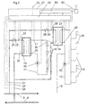
- Fig 1 discloses a district heating arrangement, which includes a heat-producing central unit 1 for providing a hot primary fluid to a number of local units 2.
- the central unit 1 may include a heating-plant or combined power and heating plant, which produces energy by oil burning, for instance.
- the central unit 1 may be any unit, which provides a hot primary fluid, for instance waste heat from any industrial process.
- the district heating arrangement includes a conduit network, which extends in a closed circuit via the central unit 1.
- the conduit network includes a feeding conduit 3 for the supply of the hot primary fluid to the local units 2, and a return conduit 4 for the re-circulation of the primary fluid to the central unit 1.
- the conduit network 3, 4 may include various sub-networks 3', 4', which all are included in the closed circuit.
- the district heating arrangement may also include subordinate networks (not disclosed), which are closed per se and connected to the conduit network 3, 4 or the sub-network 3', 4', via a heat-exchanger. The fluid in such a subordinate network is thus separated from the primary fluid.
- the district heating arrangement also includes at least one pump 5 for the circulation of the hot primary fluid via the conduit network 3, 4, 3', 4'.
- the various sub-networks 3', 4' may also include separate circulation pumps (not disclosed).
- the local units 2 may be connected to the highest hierarchy of the conduit network 3, 4 or to any sub- network 3', 4'.
- the central unit 1 includes conventional control means 6 for controlling different components of the arrangement, for instance the pump 5.
- the arrangement includes a temperature sensor 7 for sensing the temperature of the primary fluid in the return conduit 4.
- the local unit 2 includes a first secondary circuit 11 for heating and a second secondary circuit 12 for the production of hot tap water.
- the first secondary circuit 11 is connected to the conduit network 3, 4 via a first heat-exchanger 13.
- the secondary circuit 12 is connected to the conduit network 3, 4 via a second heat-exchanger 14.
- the heat-exchanger device of the local unit 2 thus includes two heat-exchanger 13, 14. However, it is to be noted that more or less heat-exchanger, may be included in this heat-exchanger device.
- the primary fluid from the conduit network 3, 4 may be conveyed directly into the radiators 15. It is also possible, for the first secondary circuit 11 and/or the second secondary circuit 12, to provide two successively arranged heat-exchangers for obtaining a preheating and a final heating of the secondary fluid in the respective secondary circuit 11, 12.
- the first secondary circuit 11 includes, except for the above mentioned radiators, also a circulation pump 16 and a temperature sensor 17.
- the second secondary circuit 12 includes a number of outlets 18, i.e. different forms of tap points for hot water. There is also an inlet conduit 19 for the supply of tap water.
- the second secondary circuit 12 includes, in the embodiment disclosed, a circulation pump 20 and a temperature sensor 21 for sensing the temperature of the outgoing secondary fluid.
- the secondary circuit 12 does not need to be closed, i.e. there is no re-circulation of tap water via a pump 20.
- the local unit 2 also includes means for realising the control of the operation of the local unit 2.
- These means include two control valves 25 and 26.
- the control valve 25 is arranged to permit control of the size of the flow of the hot primary fluid supplied to the first heat-exchanger 13. Such a control may be performed by adjustment of the valve position of the control valve 25. In such a way, the effect supplied to the first secondary circuit 11 may be controlled.
- the second control valve 26 is arranged to control the size of the flow of the primary fluid supplied to the second heat-exchanger 14 by an adjustment of the valve position.
- the control valves 25, 26 and the pumps 16, 20 are connected to a control member 27.
- sensing members 29 and 30 for sensing the valve positions of the control valves 25 and 26, respectively.
- the valve positions of the control valves 25, 26 may alternatively be determined directly in the control member 27 as a function of the control signal given to the control valves 25, 26.
- the local unit 2 may include pressure sensors 31, 32 for sensing the pressure of the primary fluid entering the local unit 2 and the primary fluid leaving the local unit 2, respectively.
- the pressure sensors 31 and 32 are suitably also connected to the control member 27.
- the temperature sensors 17 and 21 are connected to the control member 27.
- the local unit may include a plurality of further temperature sensors, which are all connected to the control member 27.
- a temperature sensor 33 is arranged to sense the outdoor temperature.
- a temperature sensor 34 is arranged to sense the temperature of the primary fluid leaving the local unit 2 and two temperature sensors 35 and 36 are arranged to sense the temperature of the primary fluid, which leaves the first heat-exchanger 13 and the second heat-exchanger 14, respectively.
- Two temperature sensors 37 and 38 are arranged to sense the temperature of the primary fluid at the inlet of the first heat-exchanger 13 and at the inlet of the second heat-exchanger 14, respectively.
- Two temperature sensors 39 and 40 are also arranged to sense the temperature of the secondary fluid, which is supplied to the first heat-exchanger 13 and the second heat-exchanger 14, respectively.
- the local units 2 also include a communication device 50, which permits communication, preferably in two directions, between the local units 2 and a receiving communication device 50.
- the communication devices 50 are connected to the control member 27.
- the central unit 1 may include such a communication device 50, which is connected to the schematically disclosed means 6.
- the communication devices 50, 51 may operate according to communication principals know per se, for instance, the communication devices 50 may include means for transferring signals by means of radio waves.
- the communication devices 50 may also be arranged to communicate via the mobile telephone network.
- each local unit 5 may include a sort of mobile phone.
- the communication devices 50, 51 may also include means for communicating via a computer network, for instance the Internet or for instance any public or private Intranet.
- the communication devices 50, 51 may include means for communication via a network for distribution of electricity. The communication may also take place via one or several of said communication manners.
- the control members 27 of the various local units 2 include a digital computer having a first unit 52 for receiving the signals from the different sensors 17, 21, 29-40 and for controlling various functions of the local unit 2.
- the first unit 52 of the control member 27 is arranged to control the control valves 25 and 26 and the pumps 16 and 20.
- the digital computer of the control device 27 may also include a second unit 53 for processing the signals from the different sensors 17, 21, 29-40, and a communication unit, which forms at least one part of the mentioned communication device 50.
- the communication device 50 is formed from conventional communication cards with associated software and modem, ISDN-units etc.
- the arrangement also includes second means, by which the local units 2 and the central unit 1 are arranged to communicate via the communication devices 51 and 50.
- These second means may consist of one or several separate units, as is indicated in Fig 1, or form a part of the central unit 1.
- the second means include in the embodiment disclosed a digital computer 61, which has a common data base 62 arranged to receive information from all the local units 2 via the communication device 51.
- the second means may also include a digital computer 63, which receives data from the data base 62 of the computer 61 and makes suitable processings.
- the computer 63 is accessible for a user.
- the computer 63 may be directly connected to the computer 61 or, as is disclosed in Fig 1, be arranged to communicate with the computer 61 by means of a communication device 64 via any network, for instance an Intranet or the Internet, via radio communication, via a network for the distribution of electricity etc.
- the arrangement may also include several computers 63 for several different users.
- the arrangement according to the invention may for instance function in the following way.
- the sensors 7, 17, 21, 27, 29-40 of each of the local units sense an instantaneous value of a respective parameter and transfer this value to the first unit 52 of the control member 27.
- the received instantaneous values are processed with respect to local operation conditions, and a parameter, which is related to the efficiency of the units, is determined.
- Local operation conditions may, for instance, include the outdoor temperature, which is given by means of the sensor 33, or the size of the flow of the primary fluid, which is given by means of the sensors 29, 30 or by means of the control signals delivered to the control valves 25, 26.
- the instantaneous value of this parameter is communicated in an automatic manner via the communication device 50 and 51 to the computer 61 and the data base 62.
- the data base 62 In the data base 62, there is thus the instantaneous value of the parameter for all local units 2.
- These values are compared with each other and a list of ranking is established. From this list, a user may recognise the local unit 2, which operates worst and which thus has the greatest need of maintenance.
- the list may be established by means of the computer 61 and stored in the data base 62. A user may thus via the computer 63 download a list and in such a way receive information about which local unit 2 that has the greatest need of maintenance.
- the list may be updated substantially continuously with new instantaneous values of the parameter.
- the establishment proper of the list may be administered in many various manners.
- the data base 62 may store merely the instantaneous values of the parameter, wherein the user takes out an actual list via the computer 63.
- a user may also receive the list directly from the computer 61, for instance as a print out or via a screen.
- Each sensor 7, 17, 21, 27, 29-40 is arranged to provide such an actual instantaneous value of the parameter at substantially each point of time. This value may then be transferred to the computer 61 and the data base 62 either continuously or when the computer 61 asks for the value of the parameter at a substantially arbitrary point of time. It is also possible to transfer the signal from the sensors 7, 17, 21, 27, 29-40 directly to the computer 61 and to make possible calculations of the parameters centrally for all or some of the local units 2.
- the signal from the sensors 34, 35, 36, which sense the temperature t' out of the primary fluid when it leaves the heat-exchanger devices 13, 14, is utilised either for each of the heat-exchanger devices 13, 14 separately or the common temperature downstream of both the heat-exchanger devices 13, 14.
- This temperature t' out may form the parameter, which is to be compared and gives a measure of the efficiency of the cooling of the heat-exchanger devices 13, 14.
- this temperature t' out may be set in relation to the signal from the sensor 7, i.e. the temperature of the primary fluid before it is supplied to the central unit 1 and when it is located downstream of the last local unit 2.
- the difference between these temperatures of the primary fluid, which is re-circulated to the central unit 1, defines if a local unit 2 is better or worse than the average. If this temperature difference is multiplied with the size of the flow through the local unit 2, a parameter, which defines the weighted contribution of the unit 2 to the total temperature of the primary fluid flowing through the return conduits 4, is given. By comparing these numbers for different local units 2, one may have a weighted_order of rang of the local units 2, which are the worst (largest negative numbers) and which are the best (largest positive numbers) with regard to the cooling.
- the signal from the sensors 37 and/or 38, which sense the temperature t' in of the primary fluid supplied to the heat-exchanger devices 13, 14, is utilised for the determination of the parameter. If also the temperature t' in of the primary fluid supplied to the heat-exchanger device is considered, an even better measure of the efficiency or the cooling of the local unit 2 is obtained.
- the signals from the sensors 17 and 21, which sense the temperature t" out of the secondary fluid when it leaves the respective heat-exchanger device 13, 14, and the signal from the sensors 39, 40, which sense the temperature t" in of the secondary fluid supplied to the respective heat-exchanger device 13, 14, may also be utilised for the determination of the parameter to be compared.
- Theta1 and Theta2 are compared for the different heat-exchangers 13 and 14, also a measure of the efficiency of the different heat-exchanger 13, 14 of the different local units 2 is obtained. It is to be noted, that a comparison of Theta1, which refers to the primary side of the heat-exchangers 13, 14, for the different local units 2 is sufficient for determining an order of rang of the need of maintenance of the heat-exchangers 13, 14. Since the size of the flow of primary fluid through the heat-exchanger 13, 14 also is considered, it may be determined how dirty these heat-exchangers are.
Landscapes
- Engineering & Computer Science (AREA)
- General Engineering & Computer Science (AREA)
- Chemical & Material Sciences (AREA)
- Thermal Sciences (AREA)
- Combustion & Propulsion (AREA)
- Mechanical Engineering (AREA)
- Physics & Mathematics (AREA)
- Steam Or Hot-Water Central Heating Systems (AREA)
- Air Conditioning Control Device (AREA)
- Central Heating Systems (AREA)
- Thermotherapy And Cooling Therapy Devices (AREA)
- Heating, Cooling, Or Curing Plastics Or The Like In General (AREA)
- Electric Stoves And Ranges (AREA)
Claims (32)
- Fernwärmeanordnung mit einer wärmeproduzierenden Zentraleinheit (1) zum Liefern eines heißen Primärfluidums sowie einer Anzahl von lokalen Einheiten (2), von denen jede eine Wärmetauschvorrichtung (13, 14) umfasst, und einem Leitungsnetzwerk (3, 4, 3', 4'), das einen Speisekreis (3, 3') zum Transportieren des Primärfluidums von der wärmeproduzierenden Einheit (1) an jede lokale Einheit (2) umfasst, wobei jede der lokalen Einheiten (2) mit dem Speisekreis (3, 3') verbunden ist und das Primärfluidum durch eine Primärseite der Wärmetauschvorrichtung (13, 14) zur Übertragung der Wärme an ein Sekundärfluidum, empfängt, das durch eine Sekundärseite der Wärmetauschvorrichtung (13, 14) strömt, wobei jede der lokalen Einheiten (2) eine erste Einrichtung (7, 17, 21, 27, 29 - 40) umfasst, die dazu dient, mindestens einen ersten Parameter zu liefern, der sich auf die Effizienz der Wärmeübertragung bezieht, dadurch gekennzeichnet, dass
jede lokale Einheit (2) eine erste Kommunikationsvorrichtung (50) umfasst, die dazu dient, einen Momentanwert des ersten Parameters an eine zweite Kommunikationsvorrichtung (51) der Anordnung zu übertragen, und dass die Anordnung eine zweite Einrichtung (61 - 63) mit einem Digitalcomputer umfasst, die mit der zweiten Kommunikationsvorrichtung (51, 64) zusammenarbeitet und dazu dient, die lokale Einheit (2) zu bestimmen, die den größten Wartungsbedarf in Abhängigkeit vom Momentanwert des ersten Parameters hat, wobei bestimmt wird, dass die lokale Einheit mit der niedrigsten Effizienz den größten Wartungsbedarf hat. - Anordnung nach Anspruch 1, dadurch gekennzeichnet, dass die zweite Einrichtung (61 - 63) dazu dient, den Wert des ersten Parameters für die lokalen Einheiten (2) zu vergleichen und eine Reihenfolge der lokalen Einheiten (2) im Hinblick auf den Wartungsbedarf der lokalen Einheiten (2) zu liefern.
- Anordnung nach einem der vorangegangenen Ansprüche, dadurch gekennzeichnet, dass die erste Einrichtung (7, 17, 21, 27, 29 - 40) dazu dient, kontinuierlich einen aktuellen Momentanwert des ersten Parameters zu liefern.
- Anordnung nach einem der vorangegangenen Ansprüche, dadurch gekennzeichnet, dass die erste Kommunikationsvorrichtung (50) jeder lokalen Einheit (2) die Kommunikation eines solchen aktuellen Momentanwertes zu einem im wesentlichen beliebigen Zeitpunkt ermöglicht.
- Anordnung nach einem der vorangegangenen Ansprüche, dadurch gekennzeichnet, dass jede lokale Einheit (2) einen Digitalcomputer (52, 53) umfasst, der mindestens teilweise die erste Einrichtung (7, 17, 21, 27, 29 - 40) umfasst und dazu dient, automatisch den Momentanwert des ersten Parameters an die zweite Einrichtung über die Kommunikationsvornchtung (50, 51) zu übermitteln.
- Anordnung nach einem der vorangegangenen Ansprüche, dadurch gekennzeichnet, dass die erste Einrichtung (7, 17, 21, 27, 29 - 40) einen ersten Sensor (34 - 36) umfasst, der dazu dient, die Temperatur des Primärfluidums zu erfassen, wenn es die Wärmetauschvorrichtung (13, 24) der lokalen Einheit (2) verlässt, wobei der Parameter sich auf diese Temperatur bezieht.
- Anordnung nach Anspruch 6, dadurch gekennzeichnet, dass die erste Einrichtung (7, 17, 21, 27, 29 - 40) einen zweiten Sensor (37, 38) umfasst, der dazu dient, die Temperatur des Primärfluidums zu erfassen, das an die Wärmetauschvorrichtung (13, 14) der lokalen Einheit (2) geliefert wird, wobei der Parameter sich auf diese Temperatur bezieht.
- Anordnung nach einem der Ansprüche 6 und 7, dadurch gekennzeichnet, dass die erste Einrichtung (7, 17, 21, 27, 29 - 40) einen dritten Sensor (17, 21) umfasst, der dazu dient, die Temperatur des Sekundärfluidums zu erfassen, wenn es die Wärmetauschvorrichtung (13, 14) der lokalen Einheit (27) verlässt, wobei der Parameter sich auf diese Temperatur bezieht.
- Vorrichtung nach Anspruch 8, dadurch gekennzeichnet, dass die erste Einrichtung (7, 17, 21, 27, 29 - 40) einen vierten Sensor (39, 40) umfasst, der dazu dient, die Temperatur des Sekundärfluidums zu erfassen, das der Wärmetauschvorrichtung (13, 14) der lokalen Einheit (2) zugeführt wird, wobei der Parameter sich auf diese Temperatur bezieht.
- Anordnung nach Anspruch 6 bis 9, dadurch gekennzeichnet, dass die erste Einrichtung (7, 17, 21, 27, 29 - 40) dazu dient, eine logarithmische mittlere Temperaturdifferenz aus den Temperaturen zu errechnen, wie sie von den ersten, zweiten, dritten und vierten Sensoren (17, 21, 34 - 40) erfasst wurden, wobei der Parameter sich auf die so berechnete Temperaturdifferenz bezieht.
- Anordnung nach Anspruch 10, dadurch gekennzeichnet, dass die erste Einrichtung (7, 17, 21, 27, 29 - 40) dazu dient, NTU-Werte aus den Temperaturen zu errechnen, wie sie von den ersten, zweiten, dritten und vierten Sensoren (17, 21, 34 - 40) errechnet wurden, wobei der Parameter sich auf diese NTU-Werte bezieht.
- Anordnung nach einem der vorangegangenen Ansprüche, dadurch gekennzeichnet, dass das Leitungsnetzwerk (3, 3', 4, 4') eine Rückführleitung (4, 4') zum Transportieren des Primärfluidums von den lokalen Einheiten (2) zurück zur Zentraleinheit (1) umfasst, wobei die Anordnung einen Sensor (7) umfasst, der dazu dient, die Temperatur des Primärfluidums in der Rückführleitung (4, 4') zu erfassen, und wobei der Parameter sich auf diese Temperatur des Primärfluidums bezieht.
- Anordnung nach einem der vorangegangenen Ansprüche, dadurch gekennzeichnet, dass die erste Einrichtung (29 bis 32) dazu dient, die Größe der Strömung des heißen Primärfluidums durch die Wärmetauschvorrichtung (13, 14) zu liefern, wobei der Parameter sich auf die Größe dieser Strömung bezieht.
- Anordnung nach einem der vorangegangenen Ansprüche, dadurch gekennzeichnet, dass jede lokale Einheit (2) ein Steuerventil (25, 26) zum Steuern der Strömung des heißen Primärfluidums durch die Wärmetauschvorrichtung (13, 14) umfasst.
- Anordnung nach Anspruch 14, dadurch gekennzeichnet, dass die erste Einrichtung (27, 29 bis 32) dazu dient, eine Ventilposition des Steuerventils (25; 26) zu liefern, wobei der Parameter sich auf diese Ventilposition bezieht.
- Anordnung nach einem der vorangegangenen Ansprüche; dadurch gekennzeichnet, dass die erste Einrichtung (31, 32) dazu dient, eine Druckdifferenz zwischen dem Primärfluidum, das an die lokale Einheit (2) geliefert wird, und dem Primärfluidum, das die lokale Einheit (2) verlässt, zu liefern, wobei der Parameter sich auf diese Druckdifferenz bezieht.
- Anordnung nach einem der vorangegangenen Ansprüche, dadurch gekennzeichnet, dass die Kommunikationsvorrichtungen (50, 51, 64) eine Kommunikationseinrichtung mittels Radiowellen beinhalten.
- Anordnung nach Anspruch 17, dadurch gekennzeichnet, dass die Kommunikationsvorrichtungen (50, 51, 64) eine Kommunikationseinrichtung über ein mobiles Telefonnetzwerk umfassen.
- Anordnung nach einem der vorangegangenen Ansprüche, dadurch gekennzeichnet, dass die Kommunikationsvorrichtungen (50, 51, 64) eine Kommunikationseinrichtung mittels eines Computernetzwerks umfassen.
- Anordnung nach einem der vorangegangenen Ansprüche, dadurch gekennzeichnet, dass die Kommunikationsvorrichtungen (50, 51, 64) eine Kommunikationseinrichtung über das Internet umfassen.
- Anordnung nach einem der vorangegangenen Ansprüche, dadurch gekennzeichnet, dass die Kommunikationsvorrichtungen (50, 51, 64) eine Kommunikationseinrichtung über ein Netzwerk zur Verteilung von Elektrizität umfassen.
- Verfahren für eine Fernwärmeanordnung mit einer wärmeproduzierenden Zentraleinheit zum Liefern eines heißen Primärfluidums sowie einer Anzahl von lokalen Einheiten, von denen jede eine Wärmetauschvorrichtung umfasst, und ein Leitungsnetzwerk, das eine Speiseleitung zum Transportieren des Primärfluidums von der wärmeproduzierenden Einheit umfasst, wobei das Verfahren die folgenden Schritte umfasst:Liefern des heißen Primärfluidums an die lokalen Einheiten über die Speiseleitung zur Übertragung von Wärme an ein Sekundärfluidum, das durch die Wärmetauschvorrichtung strömt,Liefern mindestens eines ersten Parameters, der sich auf die Effizienz der Wärmeübertragung mittels der ersten Einrichtung bezieht, gekennzeichnet durchKommunikation eines Momentanwertes des ersten Parameters mittels einer ersten Kommunikationsvorrichtung von jeder lokalen Einheit an eine zweite Kommunikationsvorrichtung der Anordnung undBestimmen der lokalen Einheit, die den größten Wartungsbedarf in Abhängigkeit von dem Momentanwert des ersten Parameters hat, mittels der zweiten Einrichtung, wobei bestimmt wird, dass die lokale Einheit mit der niedrigsten Effizienz den größten Wartungsbedarf hat.
- Verfahren nach Anspruch 22, dadurch gekennzeichnet, dass die Kommunikation eine automatische Übertragung des Momentanwertes des ersten Parameters an die zweite Einrichtung umfasst.
- Verfahren nach einem der Ansprüche 22 und 23, dadurch gekennzeichnet, dass sich der Parameter auf eine erste Temperatur des Primärfluidums bezieht, wenn es die Wärmetauschvorrichtung der lokalen Einheit verlässt.
- Verfahren nach Anspruch 24, dadurch gekennzeichnet, dass sich der Parameter auf eine zweite Temperatur des Primärfluidums bezieht, wenn es der Wärmetauschvorrichtung der lokalen Einheit zugeführt wird.
- Verfahren nach einem der Ansprüche 24 und 25, dadurch gekennzeichnet, dass sich der Parameter auf eine dritte Temperatur des Sekundärfluidums bezieht, wenn es die Wärmetauschvorrichtung der lokalen Einheit verlässt.
- Verfahren nach Anspruch 26, dadurch gekennzeichnet, dass sich der Parameter auf eine vierte Temperatur des Sekundärfluidums bezieht, wenn es der Wärmetauschvorrichtung der lokalen Einheit zugeführt wird.
- Verfahren nach Anspruch 24 bis 27, dadurch gekennzeichnet, dass sich der Parameter auf eine logarithmische mittlere Temperaturdifferenz bezieht, die aus der ersten, zweiten, dritten und vierten Temperatur errechnet wurde.
- Verfahren nach Anspruch 28, dadurch gekennzeichnet, dass sich der Parameter auf NTU-Werte bezieht, die aus den von den ersten, zweiten, dritten und vierten Sensoren erfassten Temperaturen errechnet wurden.
- Verfahren nach einem der Ansprüche 22 bis 29, dadurch gekennzeichnet, dass sich der Parameter auf die Größe der Strömung des heißen Primärfluidums durch die Wärmetauschvorrichtung bezieht.
- Verfahren nach einem der Ansprüche 22 bis 30, dadurch gekennzeichnet, dass sich der Parameter auf eine Ventilposition eines Steuerventils zum Steuern der Strömung des heißen Primärfluidums durch die Wärmetauschvorrichtung bezieht.
- Verfahren nach einem der Ansprüche 22 bis 31, dadurch gekennzeichnet, dass sich der Parameter auf eine Druckdifferenz zwischen dem Primärfluidum, das der lokalen Einheit zugeführt wird, und dem Primärfluidum, das die lokale Einheit verlässt, bezieht.
Applications Claiming Priority (3)
| Application Number | Priority Date | Filing Date | Title |
|---|---|---|---|
| SE0003855A SE517497C2 (sv) | 2000-10-24 | 2000-10-24 | Fjärrvärmearrangemang och förfarande för att driva ett fjärrvärmearangemang |
| SE0003855 | 2000-10-24 | ||
| PCT/SE2001/002320 WO2002035154A1 (en) | 2000-10-24 | 2001-10-23 | A district heating arrangement, and a method for operating a district heating arrangement |
Publications (2)
| Publication Number | Publication Date |
|---|---|
| EP1399696A1 EP1399696A1 (de) | 2004-03-24 |
| EP1399696B1 true EP1399696B1 (de) | 2006-05-17 |
Family
ID=20281542
Family Applications (1)
| Application Number | Title | Priority Date | Filing Date |
|---|---|---|---|
| EP01979154A Expired - Lifetime EP1399696B1 (de) | 2000-10-24 | 2001-10-23 | Fernheizungsanordnung und verfahren zum betrieb einer fernheizungsanordnung |
Country Status (7)
| Country | Link |
|---|---|
| EP (1) | EP1399696B1 (de) |
| AT (1) | ATE326667T1 (de) |
| AU (1) | AU2002211140A1 (de) |
| DE (1) | DE60119793T2 (de) |
| RU (1) | RU2279609C2 (de) |
| SE (1) | SE517497C2 (de) |
| WO (1) | WO2002035154A1 (de) |
Cited By (1)
| Publication number | Priority date | Publication date | Assignee | Title |
|---|---|---|---|---|
| CN103868144A (zh) * | 2013-12-31 | 2014-06-18 | 北京华大智宝电子系统有限公司 | 热计量控制装置和热计量控制系统 |
Families Citing this family (10)
| Publication number | Priority date | Publication date | Assignee | Title |
|---|---|---|---|---|
| SE530080C2 (sv) * | 2006-05-23 | 2008-02-26 | Nodais Ab | Fjärrvärmesystem |
| IL191719A (en) | 2008-05-26 | 2014-09-30 | Ran Amiran | Controlling the operation of an electrically heated water tank |
| CN102777971A (zh) * | 2011-05-11 | 2012-11-14 | 姜福海 | 集中供热用户自动控制装置 |
| EP2871539B1 (de) | 2013-11-07 | 2019-04-17 | Grundfos Holding A/S | Diagnoseverfahren zur Diagnose der korrekten Funktion eines Heizungs- und / oder Kühlsystems |
| CN103673059A (zh) * | 2013-11-08 | 2014-03-26 | 清华大学 | 一种压缩式换热机组 |
| GB2528478A (en) * | 2014-07-23 | 2016-01-27 | Thermal Integration Ltd | Fluid-heating system |
| CN105258195A (zh) * | 2015-10-27 | 2016-01-20 | 北京建筑大学 | 一种集中供热系统 |
| EP3663651A1 (de) * | 2018-12-07 | 2020-06-10 | E.ON Sverige AB | Steuerung eines thermischen energieverteilungssystems |
| EP3702683A1 (de) * | 2019-03-01 | 2020-09-02 | E.ON Sverige AB | Wärmepumpenanordnung und verfahren zu dessen regelung |
| EP3712511A1 (de) * | 2019-03-22 | 2020-09-23 | E.ON Sverige AB | Vorrichtung zur überwachungs der kommunikation zwischen einem zentralen server und der lokalen steuerung einer thermischen vorrichtung, die teil eines (fern)wärme- oder (fern)kältenetzwerks ist |
Family Cites Families (26)
| Publication number | Priority date | Publication date | Assignee | Title |
|---|---|---|---|---|
| DE1253429B (de) * | 1964-05-02 | 1967-11-02 | Samson Appbau A G | Regelvorrichtung fuer Heizungsanlagen, insbesondere solche, die von einem Fernheiznetz gespeist werden |
| DE2655513C2 (de) * | 1976-12-08 | 1985-10-24 | Joh. Vaillant Gmbh U. Co, 5630 Remscheid | Einrichtung zum Regeln der von einer Fernwärmeenergiequelle abgegebenen Wärmemenge |
| DE2732639C2 (de) * | 1977-07-19 | 1987-03-19 | Istvàn Oberwil Majoros | Vorrichtung zur Übertragung von Heizwärme von einer Wärmequelle auf Verbraucherkreise |
| NL8005223A (nl) * | 1980-09-18 | 1982-04-16 | Apparatenfabriek Warmtebouw B | Stads- of blokverwarmingssysteem. |
| NL8005222A (nl) * | 1980-09-18 | 1982-04-16 | Apparatenfabriek Warmtebouw B | Stads- of blokverwarmingssysteem. |
| US4916642A (en) * | 1981-07-31 | 1990-04-10 | O-Com, Inc. | Environmental control with multiple zone central processor means |
| US4766553A (en) * | 1984-03-23 | 1988-08-23 | Azmi Kaya | Heat exchanger performance monitor |
| SE8404711L (sv) * | 1984-09-20 | 1986-03-17 | Olsson & Nilsson Energikonsult | Effektuttagsbegrensning for abonnentcentral vid fjerrvermesystem |
| SU1267120A1 (ru) * | 1985-02-04 | 1986-10-30 | Предприятие П/Я В-2616 | Система автоматического регулировани теплового пункта |
| DE3505082A1 (de) * | 1985-02-14 | 1986-08-14 | Meinrad 7407 Rottenburg Grammer | Uebergabestation fuer das fernwaermenetz |
| GB2171506B (en) * | 1985-02-21 | 1988-03-02 | Apv Uk | Plate heat transfer apparatus |
| SE464428B (sv) * | 1985-04-23 | 1991-04-22 | Cairenius | Anordning foer styrning och reglering av energitillfoerseln till en vaermevaexlare |
| CH674412A5 (de) * | 1987-09-09 | 1990-05-31 | Steinemann Ag | |
| SU1555600A1 (ru) * | 1988-02-25 | 1990-04-07 | Целиноградский сельскохозяйственный институт | Система централизованного регулировани отпуска теплоты тепличному комбинату |
| FR2651866B1 (fr) * | 1989-09-14 | 1992-04-17 | En Et | Installation collective de chauffage et/ou de distribution d'eau chaude sanitaire. |
| SU1687115A1 (ru) * | 1989-10-25 | 1991-10-30 | Целиноградский сельскохозяйственный институт | Способ теплоснабжени тепличного комбината и система дл его осуществлени |
| US5319641A (en) * | 1990-12-03 | 1994-06-07 | Echelon Systems Corp. | Multiaccess carrier sensing network communication protocol with priority messages |
| DE4333270A1 (de) * | 1993-09-27 | 1995-03-30 | Hain Geraete Und Anlagenbau Gm | Verfahren und Anordnung zur vorrangigen Aufbereitung von Warmwasser in einer Fernwärme-Kompakt-Station |
| HU931U (en) * | 1995-08-31 | 1996-10-28 | Helgert | Subscription-type subcentre system sanitary installation |
| DE19604189A1 (de) * | 1996-02-06 | 1997-08-07 | Marek Dipl Ing Gross | Gerätesystem und Verfahren zur automatischen Wärmemengenbegrenzung und zur Wärmeleistungsregelung von Fernwärmeanlagen |
| DE19618415C2 (de) * | 1996-05-08 | 2000-12-14 | Baelz Gmbh Helmut | Integrierte Wärmetauschereinheit |
| RU2144162C1 (ru) * | 1996-07-16 | 2000-01-10 | Кричке Владимир Оскарович | Автоматизированная система для измерения и учета расхода теплоносителя и тепла в системах теплоснабжения |
| US5711480A (en) * | 1996-10-15 | 1998-01-27 | Carrier Corporation | Low-cost wireless HVAC systems |
| RU2154239C2 (ru) * | 1998-09-29 | 2000-08-10 | Открытое акционерное общество "Петербургская телефонная сеть" | Способ отопления помещений многоэтажных зданий и устройство, его реализующее |
| DE19859364C2 (de) * | 1998-12-22 | 2001-09-13 | Baelz Gmbh Helmut | Wärmeversorgungsanlage mit Spitzenlastbegrenzung |
| AT409698B (de) * | 1999-02-23 | 2002-10-25 | Vaillant Gmbh | Heizgerät |
-
2000
- 2000-10-24 SE SE0003855A patent/SE517497C2/sv not_active IP Right Cessation
-
2001
- 2001-10-23 RU RU2003115440/06A patent/RU2279609C2/ru not_active IP Right Cessation
- 2001-10-23 EP EP01979154A patent/EP1399696B1/de not_active Expired - Lifetime
- 2001-10-23 AU AU2002211140A patent/AU2002211140A1/en not_active Abandoned
- 2001-10-23 WO PCT/SE2001/002320 patent/WO2002035154A1/en not_active Ceased
- 2001-10-23 DE DE60119793T patent/DE60119793T2/de not_active Expired - Lifetime
- 2001-10-23 AT AT01979154T patent/ATE326667T1/de not_active IP Right Cessation
Cited By (2)
| Publication number | Priority date | Publication date | Assignee | Title |
|---|---|---|---|---|
| CN103868144A (zh) * | 2013-12-31 | 2014-06-18 | 北京华大智宝电子系统有限公司 | 热计量控制装置和热计量控制系统 |
| CN103868144B (zh) * | 2013-12-31 | 2017-02-15 | 北京华大智宝电子系统有限公司 | 热计量控制装置和热计量控制系统 |
Also Published As
| Publication number | Publication date |
|---|---|
| WO2002035154A1 (en) | 2002-05-02 |
| DE60119793T2 (de) | 2007-04-26 |
| RU2279609C2 (ru) | 2006-07-10 |
| AU2002211140A1 (en) | 2002-05-06 |
| SE0003855L (sv) | 2002-04-25 |
| DE60119793D1 (de) | 2006-06-22 |
| SE0003855D0 (sv) | 2000-10-24 |
| ATE326667T1 (de) | 2006-06-15 |
| EP1399696A1 (de) | 2004-03-24 |
| SE517497C2 (sv) | 2002-06-11 |
Similar Documents
| Publication | Publication Date | Title |
|---|---|---|
| EP1399696B1 (de) | Fernheizungsanordnung und verfahren zum betrieb einer fernheizungsanordnung | |
| EP3371515B1 (de) | Lokale verbraucheranordnung von wärmeenergie und lokale erzeugeranordnung für wärmeenergie für ein fernwärmeenergieverteilungssystem | |
| CN103190050A (zh) | 用于热能存储模块的智能式电子接口以及用于存储的热能和热能存储容量交易的方法 | |
| CN103370577A (zh) | 加热器和用于控制加热器的方法 | |
| EP3891437B1 (de) | Steuerung eines thermischen energieverteilungssystems | |
| CN108629444B (zh) | 基于多智能体控制方法的分布式多区域供热方法及系统 | |
| EP3569935B1 (de) | Reversible wärmepumpenanlage und fernwärmeverteilungssystem mit solch einer reversiblen wärmepumpenanlage | |
| RU2269063C2 (ru) | Система теплоцентрали, локальный блок системы теплоцентрали, блок управления для локального блока и способ функционирования системы теплоцентрали | |
| CN113883662A (zh) | 热能系统中的功率消耗的控制 | |
| CN104797891A (zh) | 锅炉的利用外部网络的室外温度补偿控制方法 | |
| CN113065249B (zh) | 一种供热系统供回水温度预测方法及装置 | |
| RU2003115440A (ru) | Система централизованного теплоснабжения и способ работы системы централизованного теплоснабжения | |
| EP3732400B1 (de) | Verfahren zur verbesserten nutzung von stromnetzen | |
| KR20160059849A (ko) | 지역난방 열에너지 통합 관리시스템 | |
| CN119983785A (zh) | 一种竖炉余热循环利用的节能监测系统 | |
| KR100633238B1 (ko) | 다수의 축열조를 한 배관망에 직접 연결 및 운전할 수 있는지역난방용 축열조 시스템 | |
| CN108518717A (zh) | 一种市政供热系统、供热方法及计费方法 | |
| CN208170493U (zh) | 一种市政供热系统 | |
| Vašek et al. | Heat production and distribution control system based on holonic concept | |
| EP3879187A1 (de) | Verbesserter wirkungsgrad für ein wärmeextraktionssystem und/oder ein wärmeabgabesystem | |
| CN215062324U (zh) | 一种基于燃气冷凝锅炉与中深层地热混合的多元清洁供热系统 | |
| DE10117112A1 (de) | Alternierend genutzte Heizung mit getrennter Verbrauchserfassung | |
| EP4008969A1 (de) | Vorrichtung zum ausgleichen thermischer energie | |
| CN117029073A (zh) | 一种多变量耦合的热网疏水泵控制方法 | |
| Broniszewski et al. | Assessment of possibilities for reusing waste heat to cover needs for heating in Bulten Poland SA |
Legal Events
| Date | Code | Title | Description |
|---|---|---|---|
| PUAI | Public reference made under article 153(3) epc to a published international application that has entered the european phase |
Free format text: ORIGINAL CODE: 0009012 |
|
| 17P | Request for examination filed |
Effective date: 20030128 |
|
| AK | Designated contracting states |
Kind code of ref document: A1 Designated state(s): AT BE CH CY DE DK ES FI FR GB GR IE IT LI LU MC NL PT SE TR |
|
| AX | Request for extension of the european patent |
Extension state: LT LV |
|
| 17Q | First examination report despatched |
Effective date: 20050211 |
|
| GRAP | Despatch of communication of intention to grant a patent |
Free format text: ORIGINAL CODE: EPIDOSNIGR1 |
|
| GRAS | Grant fee paid |
Free format text: ORIGINAL CODE: EPIDOSNIGR3 |
|
| GRAA | (expected) grant |
Free format text: ORIGINAL CODE: 0009210 |
|
| RIN1 | Information on inventor provided before grant (corrected) |
Inventor name: ENANDER, ANDERS, PATRIK, TORBJOERN Inventor name: LARSSON, JAN, ERIK Inventor name: ENGSTROEM, JAN, ANDERS, AKE Inventor name: PERSSON, MATS, HENRIK Inventor name: HELIN, PEROLA, MAGNUS |
|
| AK | Designated contracting states |
Kind code of ref document: B1 Designated state(s): AT BE CH CY DE DK ES FI FR GB GR IE IT LI LU MC NL PT SE TR |
|
| AX | Request for extension of the european patent |
Extension state: LT LV |
|
| PG25 | Lapsed in a contracting state [announced via postgrant information from national office to epo] |
Ref country code: IT Free format text: LAPSE BECAUSE OF FAILURE TO SUBMIT A TRANSLATION OF THE DESCRIPTION OR TO PAY THE FEE WITHIN THE PRESCRIBED TIME-LIMIT;WARNING: LAPSES OF ITALIAN PATENTS WITH EFFECTIVE DATE BEFORE 2007 MAY HAVE OCCURRED AT ANY TIME BEFORE 2007. THE CORRECT EFFECTIVE DATE MAY BE DIFFERENT FROM THE ONE RECORDED. Effective date: 20060517 Ref country code: NL Free format text: LAPSE BECAUSE OF FAILURE TO SUBMIT A TRANSLATION OF THE DESCRIPTION OR TO PAY THE FEE WITHIN THE PRESCRIBED TIME-LIMIT Effective date: 20060517 Ref country code: CH Free format text: LAPSE BECAUSE OF FAILURE TO SUBMIT A TRANSLATION OF THE DESCRIPTION OR TO PAY THE FEE WITHIN THE PRESCRIBED TIME-LIMIT Effective date: 20060517 Ref country code: LI Free format text: LAPSE BECAUSE OF FAILURE TO SUBMIT A TRANSLATION OF THE DESCRIPTION OR TO PAY THE FEE WITHIN THE PRESCRIBED TIME-LIMIT Effective date: 20060517 Ref country code: BE Free format text: LAPSE BECAUSE OF FAILURE TO SUBMIT A TRANSLATION OF THE DESCRIPTION OR TO PAY THE FEE WITHIN THE PRESCRIBED TIME-LIMIT Effective date: 20060517 Ref country code: AT Free format text: LAPSE BECAUSE OF FAILURE TO SUBMIT A TRANSLATION OF THE DESCRIPTION OR TO PAY THE FEE WITHIN THE PRESCRIBED TIME-LIMIT Effective date: 20060517 |
|
| REG | Reference to a national code |
Ref country code: GB Ref legal event code: FG4D |
|
| REG | Reference to a national code |
Ref country code: CH Ref legal event code: EP |
|
| REG | Reference to a national code |
Ref country code: IE Ref legal event code: FG4D |
|
| REF | Corresponds to: |
Ref document number: 60119793 Country of ref document: DE Date of ref document: 20060622 Kind code of ref document: P |
|
| PG25 | Lapsed in a contracting state [announced via postgrant information from national office to epo] |
Ref country code: DK Free format text: LAPSE BECAUSE OF FAILURE TO SUBMIT A TRANSLATION OF THE DESCRIPTION OR TO PAY THE FEE WITHIN THE PRESCRIBED TIME-LIMIT Effective date: 20060817 Ref country code: SE Free format text: LAPSE BECAUSE OF FAILURE TO SUBMIT A TRANSLATION OF THE DESCRIPTION OR TO PAY THE FEE WITHIN THE PRESCRIBED TIME-LIMIT Effective date: 20060817 |
|
| PG25 | Lapsed in a contracting state [announced via postgrant information from national office to epo] |
Ref country code: ES Free format text: LAPSE BECAUSE OF FAILURE TO SUBMIT A TRANSLATION OF THE DESCRIPTION OR TO PAY THE FEE WITHIN THE PRESCRIBED TIME-LIMIT Effective date: 20060828 |
|
| PG25 | Lapsed in a contracting state [announced via postgrant information from national office to epo] |
Ref country code: PT Free format text: LAPSE BECAUSE OF FAILURE TO SUBMIT A TRANSLATION OF THE DESCRIPTION OR TO PAY THE FEE WITHIN THE PRESCRIBED TIME-LIMIT Effective date: 20061017 |
|
| PG25 | Lapsed in a contracting state [announced via postgrant information from national office to epo] |
Ref country code: IE Free format text: LAPSE BECAUSE OF NON-PAYMENT OF DUE FEES Effective date: 20061023 |
|
| LTIE | Lt: invalidation of european patent or patent extension |
Effective date: 20060517 |
|
| PG25 | Lapsed in a contracting state [announced via postgrant information from national office to epo] |
Ref country code: MC Free format text: LAPSE BECAUSE OF NON-PAYMENT OF DUE FEES Effective date: 20061031 |
|
| NLV1 | Nl: lapsed or annulled due to failure to fulfill the requirements of art. 29p and 29m of the patents act | ||
| REG | Reference to a national code |
Ref country code: CH Ref legal event code: PL |
|
| PLBE | No opposition filed within time limit |
Free format text: ORIGINAL CODE: 0009261 |
|
| STAA | Information on the status of an ep patent application or granted ep patent |
Free format text: STATUS: NO OPPOSITION FILED WITHIN TIME LIMIT |
|
| 26N | No opposition filed |
Effective date: 20070220 |
|
| EN | Fr: translation not filed | ||
| PG25 | Lapsed in a contracting state [announced via postgrant information from national office to epo] |
Ref country code: FR Free format text: LAPSE BECAUSE OF FAILURE TO SUBMIT A TRANSLATION OF THE DESCRIPTION OR TO PAY THE FEE WITHIN THE PRESCRIBED TIME-LIMIT Effective date: 20070309 Ref country code: GR Free format text: LAPSE BECAUSE OF FAILURE TO SUBMIT A TRANSLATION OF THE DESCRIPTION OR TO PAY THE FEE WITHIN THE PRESCRIBED TIME-LIMIT Effective date: 20060818 |
|
| PG25 | Lapsed in a contracting state [announced via postgrant information from national office to epo] |
Ref country code: TR Free format text: LAPSE BECAUSE OF FAILURE TO SUBMIT A TRANSLATION OF THE DESCRIPTION OR TO PAY THE FEE WITHIN THE PRESCRIBED TIME-LIMIT Effective date: 20060517 Ref country code: LU Free format text: LAPSE BECAUSE OF NON-PAYMENT OF DUE FEES Effective date: 20061023 |
|
| PG25 | Lapsed in a contracting state [announced via postgrant information from national office to epo] |
Ref country code: CY Free format text: LAPSE BECAUSE OF FAILURE TO SUBMIT A TRANSLATION OF THE DESCRIPTION OR TO PAY THE FEE WITHIN THE PRESCRIBED TIME-LIMIT Effective date: 20060517 Ref country code: FR Free format text: LAPSE BECAUSE OF FAILURE TO SUBMIT A TRANSLATION OF THE DESCRIPTION OR TO PAY THE FEE WITHIN THE PRESCRIBED TIME-LIMIT Effective date: 20060517 |
|
| PGFP | Annual fee paid to national office [announced via postgrant information from national office to epo] |
Ref country code: FI Payment date: 20101014 Year of fee payment: 10 Ref country code: DE Payment date: 20101020 Year of fee payment: 10 |
|
| PGFP | Annual fee paid to national office [announced via postgrant information from national office to epo] |
Ref country code: GB Payment date: 20101020 Year of fee payment: 10 |
|
| GBPC | Gb: european patent ceased through non-payment of renewal fee |
Effective date: 20111023 |
|
| PG25 | Lapsed in a contracting state [announced via postgrant information from national office to epo] |
Ref country code: DE Free format text: LAPSE BECAUSE OF NON-PAYMENT OF DUE FEES Effective date: 20120501 |
|
| REG | Reference to a national code |
Ref country code: DE Ref legal event code: R119 Ref document number: 60119793 Country of ref document: DE Effective date: 20120501 |
|
| PG25 | Lapsed in a contracting state [announced via postgrant information from national office to epo] |
Ref country code: GB Free format text: LAPSE BECAUSE OF NON-PAYMENT OF DUE FEES Effective date: 20111023 Ref country code: FI Free format text: LAPSE BECAUSE OF NON-PAYMENT OF DUE FEES Effective date: 20111023 |